
PNNL-11441
UC-701
ELECTRICALLY SWITCHED
CESIUM ION EXCHANGE
FY 1996 Annual Report
Michael A. Lilga
Rick J. Orth
Johanes P. H. Sukamto
Daniel T. Schwartz
Scott M. Haight
University of Washington
David Genders
Electrosynthesis Company, Inc.
December 1996
Prepared for
the Office of Science and Technology
U.S.
Department of Energy's Office of Environmental Management
Efficient Separations and Processing Crosscutting Program
under Contract DE-AC06-76RLO 1830
Pacific Northwest National Laboratory
Richland, Washington 99352


Summary
An electrochemical method for metal ion separations, called Electrically Switched Ion Exchange
(ESIX), is described in this report. In this method, direct oxidation and reduction of an electroactive
film attached to an electrode surface is used to load and unload the film with alkali metal cations.
The electroactive films under investigation are nickel hexacyanoferrates, which are deposited on the
surface by applying an anodic potential to a nickel electrode in a solution containing the ferricyanide
anion. Reported film preparation procedures have been modified to produce films with improved
capacity and stability. Electrochemical behavior of the derivatized electrodes has been investigated
with use of cyclic voltammetry and chronocoulometry. The films show selectivity for cesium in
concentrated sodium solutions. Raman spectroscopy has been used to directly monitor changes in
oxidation state of the film and imaging experiments have demonstrated that the redox reactions are
spatially homogeneous across the film. Requirements for a bench scale unit have been identified.
m


DISCLAIMER
Portions of this document may be illegible
in electronic image products. Images are
produced from the best available original
document*

Acknowledgments
This work was funded by the Office of Science and Technology within the Department of
Energy's Office of Environmental Management and under the Efficient Separations and Processing
Crosscutting Program.


Acronyms and Abbreviations
A electrode surface area
A amps
C charge
C Coulombs
CQ
concentration
of
electroactive film
Daw apparent diffusion coefficient
DOE U.S. Department
of
Energy
EIX electrochemical
ion
exchange
ESIX electrically switched
ion
exchange
F Faraday constant
HLW high-level waste
IX
ion
exchange
LLW low-level waste
NRC U.S. Nuclear Regulatory Commission
SCE saturated calomel electrode
/
time
TFE poly(tetrafluoroethylene)
V volts
vn


Contents
Summary iii
Acknowledgments v
Acronyms and Abbreviations vii
1.0 Introduction . 1.1
2.0 Work Accomplished : . . 2.1
2.1 Experimental 2.1
2.2 Results and Discussion 2.2
2.2.1 Comparison of Film Preparation Methods 2.2
2.2.2 Cesium Uptake/Elution 2.4
2.2.3 Estimation of Rates of Ion Loading and Unloading 2.9
2.2.4 Film Characterization Using Raman Spectroscopy 2.12
2.2.5 Scale-up Considerations 2.13
3.0 Conclusions 3.1
4.0 References 4.1
Appendix A.I
IX
Figures
1 The ESIX concept for metal ion loading and unloading 1.2
2 Cyclic voltammetry of a bare nickel electrode in 1 M NaNO
3
2.3
3 Cyclic voltammetry in 1 M NaNO
3
of hexacyanoferrate films prepared by three different
methods (Cycle #2) 2.3
4 Charge passed as determined by integration of a single potential cycle (Cycle #2) for
three film preparations 2.5
5 Repeated potential cycling of PNNL-1 in 1 M NaNO
3
2.5
6 Maximum charge passed as a function of cycle number for three different film
preparations (cyclic voltammetry in 1 M NaNO
3
) 2.6
7 Normalized maximum charge as a function of cycle number for three different film
preparations (cyclic voltammetry in 1 M NaNO
3
) 2.6
8 Cyclic voltammetry for a film in the cesium form and after two and 25 potential cycles
in 1 M NaNO
3
2.7
9 Cyclic voltammetry of a film in the sodium form and after two potential cycles in
1 M CsNO
3
2.8
10 Loading of a film in the sodium form in 1 M NaNO
3
and the same film in the cesium
form in 1 M CsNO
3
2.9
11 Normalized charge as a function of time for three different film preparations (from
cyclic voltammetry in 1 M NaNO
3
) 2.10
12 Potential step loading (0.25 V) and unloading (0.50 V) of a film prepared by the
literature method 2.11
13 Cottrell plot for unloading sodium from a film prepared by the literature method 2.11
14 Raman spectra of hexacyanoferrate films on a nickel wire as a function of
applied potential 2.12
15 Imaging Raman spectra of a literature film on a nickel wire showing spatially
homogeneous redox reactions 2.14
x

1.0 Introduction
A variety of waste types containing radioactive
137
Cs are found throughout the U.S. Department of
Energy (DOE) complex. These waste types include reactor cooling basins (Hanford, Savannah River),
underground storage tanks containing high-level radioactive waste (Savannah River, Idaho, Oak Ridge,
and Hanford), and occasionally groundwater (Idaho). Safety and regulatory requirements and
economic considerations necessitate the removal of radiocesium before these wastes can be permanently
disposed of as low-level waste (LLW) (Gephart and Lundgren 1995; PNNL 1996).
Underground storage tanks contain high-level mixed wastes in forms of sludge, salt cake, and
alkaline supernatant liquors. The current treatment scenario for this waste includes vitrification of the
high-level waste (HLW) for storage in a geologic repository and immobilization of the LLW for
near-surface disposal. Because of the high cost of HLW disposal, separation and concentration of the
radionuclides is needed to minimize the volume of HLW so that most of the waste may be disposed of
less expensively as LLW. Although the disposal requirements for LLW at Hanford have not been set,
the Nuclear Regulatory Commission (NRG) Class A waste form can contain no more than 1 Ci/m
3
.
Using the volume reduction achievable by the current vitrification technology, the concentration of
I37
Cs in the feed to the LLW vitrifier may be at most 0.42 Ci/m
3
(Kurath et al. 1994). Accounting for
the non-radioactive cesium in the waste (mass
137
Cs/total Cs mass = 0.38), the highest allowable total
cesium concentration in the feed would be about 9.3 x 10'
8
M. The concentration of cesium in tank
waste depends on which process generated the waste, but the highest is on the order of 5.1 x 10
4
M,
requiring the separation process to have a decontamination factor of at least 5500 (Kurath et al. 1994).
The separation must also be selective for cesium in the presence of sodium concentrations that can be
10
5
times higher.
Spent nuclear fuel storage basins and groundwater contain radioactive cesium and other radio-
nuclides at much lower concentrations. For example, the cesium concentration in groundwater at the
Test Area North at the Idaho National Engineering Laboratory is on the order of 50 ppb (3.6 x 10'
7
M)
(PNNL 1996). The K East Basin at Hanford contains about 4.3 iiCi/L (3.6 x 10"
10
M) of
137
Cs resulting
from corrosion of the fuel and its containers. A method of removing cesium is needed that avoids
transuranic loading of the ion exchange material and does not generate large quantities of secondary
waste.
Currently, the most accepted option for cesium separation before final disposal is conventional ion
exchange (IX) (Kurath et al. 1994). Both inorganic and organic ion exchangers are under consider-
ation. Unfortunately, in the current state of IX technology, a large amount of secondary waste is
generated due to the numerous process steps required (acid elution, exchanger water rinse, and sodium
loading of the exchanger). Neutralization of the acidic eluant typically adds sodium to the waste,
restricting the choice of waste form and limiting the amount of waste that can be incorporated. In
addition, it has been reported that organic exchangers lose approximately 3% of their capacity per
cycle (Kurath et al. 1994). Therefore, typical organic exchangers can be used for only 20 to 30 cycles
before they must also be disposed of as another form of secondary waste.
1.1

Electrically Switched Ion Exchange (ESIX) is an approach for radioactive cesium separation that
combines IX and electrochemistry to provide a selective and reversible separation method, which
should produce little or no secondary waste. In the ESIX process (Figure 1), an electroactive IX film
is electrochemically deposited onto a high-surface area electrode, and the IX characteristics (ion uptake
and elution) are controlled directly by modulating the potential of the film. For cesium, the
electroactive films under investigation are ferrocyanides, which are well-known ion exchangers (Barton
et al. 1958; Harjula et al. 1994; KouWm et al. 1964; Lehto and Harjula 1987; Lehto et al. 1987;
Loewenschuss 1982; Loos-Neskovic and Fedoroff 1984-1989b; Loos-Neskovic et al. 1976a, 1976b;
Prout et al. 1965; Tusa et al. 1994) having high selectivities for cesium in concentrated sodium
solutions (Barton et al. 1958; Harjula et al. 1994; Loos-Neskovic et al. 1976a, 1976b; Prout et al.
1965;
Tusa et al. 1994). A similar system using Prussian Blue films on a platinum electrode for metal
ion separations has been reported (Ikeshoji 1986). When a cathodic potential is applied to the film,
Fe
+3
is reduced to the Fe
+2
state, and a cation must be intercalated into the film to maintain charge
neutrality (i.e., cesium is loaded). Conversely, if an anodic potential is applied, a cation must be
released from the film (i.e., cesium is unloaded). Therefore, to load the film with cesium, the film is
reduced; to unload cesium, the film is oxidized.
The combination of IX and electrochemistry has been attempted previously. The most successful
attempt has been the electrochemical ion exchange (EEK) technology developed by AEA Technology,
United Kingdom (Bridger et al. 1991; Jones et al. 1992). In EIX, the IX properties of an
exchanger/electrode are controlled by generating acid and base locally by water electrolysis. ESIX is
significantly different because the uptake and elution of ionic species in a modified electrode or IX film
are controlled by modulating the potential of the film directly without changing the local interfacial pH.
+ Cs
+
+ e"
Load Cycle
Unload Cycle
Figure 1. The ESIX concept for metal ion loading and loading
1.2

Furthermore, the potentials used in this method do not result in the electrolysis of water, leading to
more efficient use of electrical energy and eliminating the safety issues associated with hydrogen
evolution.
A potential advantage of the ESIX process is that it may be possible to elute cesium into the same
elution solution after several load cycles because the unload step is conducted electrochemically without
added chemicals and independent of the soluble cesium concentration. This improved process would
result in the generation of a waste stream with a very low sodium concentration and a cesium
concentration that is limited only by solubility, radiation, and heat generation. Such a HLW feed
stream could allow consideration of a broader range of final waste forms, including those that cannot
tolerate sodium. This process also should not produce significant amounts of secondary waste
requiring disposal as LLW, since the elution, wash, and regeneration cycles typical of standard IX are
not necessary. A small amount of wash solution may be necessary, but this solution could be used in
subsequent cycles for unloading the exchanger. Ratios of the volume of generated secondary waste to
the volume of processed waste are estimated to be as low as 0.0006 for the ESIX process, or about two
orders of magnitude lower than for a typical process using CS-100 ion exchange resin.
Modification of electrode surfaces with electroactive films has been studied extensively (Andrieux
and Saveant 1980; Laviron 1980; Murray 1980, 1984). In particular, the preparation and
characteristics of ferrocyanide films have been reported by several groups (Bacskai et al. 1995;
Bocarsly and Sinha 1982a, 1982b; Humphrey et al. 1984, 1987; Itaya et al. 1986; Lasky and Buttry
1988;
Schneemeyer et al. 1985; Sinha et al. 1984). Nickel ferrocyanide films, M
2
NiFe(CN)
6
(M =
Na, K), have been prepared by dipping a nickel electrode into a Fe(CN)
6
"
3
solution, which oxidizes the
metal electrode to precipitate the electroactive film, or more commonly by electrochemically oxidizing
the nickel electrode in a Fe(CN)
6
3
solution (Bacskai et al. 1995; Sinha et al. 1984). Electrochemical
deposition gave the most reproducible films with highly reversible behavior. Bocarsly and Sinha
(1982b) found that the redox potential and electron transfer properties of the films demonstrated a
dependance on the alkali metal cation present in the supporting electrolyte, with cesium ion greatly
affecting the observed behavior. Films showed selectivity for metal cations in the order cesium >
potassium > sodium (Sinha et al. 1984); however, the main purpose of these studies apparently was
electrocatalysis (Humphrey et al. 1987), not ion separations. Selectivity is believed to be dependant on
metal ion size (Schneemeyer et al. 1985) and cation loading and unloading apparently require solvent
transport (Lasky and Buttry 1988).
The overall goal of the research reported here is to develop the ESIX technology for metal ion
separation. Initial work has focused on developing deposition methods that generate films with higher
capacity and stability. Cyclic voltammetry and chronocoulometry are used to characterize film
stability, capacity, and rates of metal ion uptake. Raman spectroscopy is being used to investigate
mechanisms of film loss. Initial results of this research are reported in Section 2.2 Results and
Discussion.
1.3
2.0 Work Accomplished
Research completed in FY 1996 focused on the preparation of electroactive hexacyanoferrate films
having improved capacity and stability. Films were prepared using modifications to the published
procedures. Testing was conducted with cyclic voltammetry, chronocoulometry, and with Raman
spectroscopy. Details of the experimental procedures are reported in Section 2.1 and findings are
discussed in Section 2.2.
2.1 Experimental
A PAR 273A potentiostat/galvanostat was used to deposit and characterize films. Potentials were
recorded versus a saturated calomel electrode (SCE). In basic solutions, a Zitex filter membrane made
of poly(trifluoroethylene) (TFE) was used in the SCE for improved stability. Experiments were
controlled and data collected with a Dell 466/MX computer via a GPIB card using LabView™ software.
A 99.98% pure nickel substrate (Goodfellow) was used as the electrode. In one experimental
setup,
disks of 1.27-cm-diameter (1.27 cm
2
) were embedded in epoxy, polished, and suspended in the
test solution. In another apparatus, a nickel plate was sealed to a specially built electrochemical cell
with an o-ring and clamp. The exposed portion of the electrode had a diameter of 1.90 cm (2.84 cm
2
).
Prior to each film deposition, the substrate was abraded using a 600-grit sandpaper and thoroughly
rinsed. Three different deposition procedures were used. One procedure was similar to that of
Bocarsly and Sinha (1982a, 1982b), where the nickel surface was exposed to a solution of 5 mM
K
3
Fe(CN)
6
and 0.1 M KNO
3
and a 1.0 V (SCE) potential was applied to the nickel electrode for 300 s.
This method is designated the "literature" procedure. One variant of this method, entailing application
of 0.65 V for 10 min followed by 1 V for 30 min, was used to prepare films for chronocoulometry
experiments. The other procedures were PNNL proprietary methods designated as PNNL-1 and
PNNL-2. All chemicals were A.C.S. reagent grade and solutions were prepared with 18.2 MQ-cm
water.
A nickel sponge electrode (Electrosynthesis Co., Inc.) with a nominal surface area per volume of
13 cm
2
/cm
3
(20 pores per inch, ppi) was also coated with a nickel hexacyanoferrate film using the
literature procedure and tested.
The characteristics of the films were determined by use of cyclic voltammetry and chrono-
coulometry. Cyclic voltammetry was typically conducted in 1 M NaNO
3
or 1 M CsNO
3
solutions
starting from an applied potential of 0.25 V, scanning anodically to 0.8 V, then cathodically to -0.1 V,
returning to 0.25 V (SCE) at a scan rate of 50 mV/s. Chronocoulometry was conducted by stepping to
0.25 V (SCE) to load the film and to 0.5 V (SCE) to unload the film, typically in 0.5
Raman spectra were acquired using the 647.1 nm line of a krypton ion laser (Laser Ionics). The
647.1 nm line is a sensitive probe of the oxidation state of the film and gives minimal film degradation
because it lies outside the absorption window of the material. Plasma emissions from the laser were
2.1

removed with a narrow bandpass filter (Omega Optical). The laser was focused using an f/10 spherical
lens.
Scattered light was collected at 90° from the incident beam by an f/1.2 Nikon camera lens. The
elastically scattered portion of the light was attenuated by an OD6 holographic notch filter (Kaiser
Optical) prior to entering the spectrograph through a 100 pm entrance slit. A 270 cm, f/4 imaging
spectrograph (Spex Industries model 270M) equipped with 600 and 1800 gr/mm gratings dispersed the
inelastically scattered light onto a liquid nitrogen cooled two-dimensional CCD array (Princeton
Instruments model LN/CCD-1024E). The spectroscopic and electrochemical instrumentation was
controlled by a Macintosh Centris 650 computer running Lab View v.2.2.1 over a GPIB interface.
Spectra were acquired in situ from 500-/mn-diameter Ni disk and wire electrodes that were coated with
a film and immersed in the sodium nitrate electrolyte. Additional details regarding the
spectroelectrochemical instrumentation have been reported previously (Haight and Schwartz 1995).
2.2 Results and Discussion
This section presents the results of studies to make films with increased capacity and stability.
Included are discussions of cesium loading and unloading and efforts to characterize the films using
Raman spectroscopy. An initial engineering evaluation is also presented.
2.2.1 Comparison of Film Preparation Methods
Films were prepared on a nickel substrate by applying an anodic potential in a solution containing
K
3
Fe(CN)
6
. The film is formed when Ni
+2
ion generated at the electrode surface reacts with the
ferricyanide anion to precipitate the insoluble nickel hexacyanpferrate material on the electrode surface
(Eq. 1). Once the electrode has been coated, it displays the properties of the nickel hexacyanoferrate,
Ni
c
K
3
Fe(CN)
6
KNiFe(CN)
6
+ 2 K
+
+ 2 e"
(1)
rather than the substrate on which it was deposited. For example, Figure 2 shows a cyclic
voltammogram of a bare nickel electrode in 1 M CsNO
3
electrolyte. Within the potential range
studied, only a small amount of current is passed associated with oxidation of the nickel surface. The
current on the 5th cycle is larger than that on the 15th cycle because the electrode surface passivates as
an oxide coating forms. Figure 3 shows cyclic voltammetry in 1 M NaNO
3
electrolyte of films
prepared by three different deposition protocols. The redox behavior of the surface-bound
hexacyanoferrate is readily apparent.
Cyclic voltammetry shows that the ferrocyanide film may be oxidized to the ferricyanide form,
which may in turn be reduced back to the ferrocyanide form. Eqs. 2 and 3, respectively, illustrate
these reactions for any alkali metal counterion (M
+
). Note that reduction requires uptake of a metal
ion, M
+
, and oxidation requires release of the ion to retain charge neutrality in the film.
M
2
NiFe"(CN)
6
-»
MNiFe
ffl
(CN)
6
+ e"
MNiFe
m
(CN)
6
+ e" + M
+
+ M
+
-» M
2
NiFe"(CN)
6
(2)
(3)
2.2

0.4-
0.3
-
0.2:
1
0.1
-
"£
oo
-
|
-0.1
-
°
-o.2:
-0.3
-
-0.4-
-0.5
-
—i—i—i—|—i—i—i—i
Cycle
5
Cycle
15
—i—i—i—I—i—i—i—i—i—i—i—i—i—
-200
0 200 400 600
Applied Potential,
mV
(SCE)
800
Figure
2.
Cyclic voltammetry
of a
bare nickel electrode
in 1 M
NaNO
3
3.5
2.5
1.5-
E
-
0.5 --
2
-0.5 -
o
-1.5
-2.5
-3.5
-200
PNNL-2
PNNL-1
Literature
H
1—I—I—I—i—I—I—I—I—I—I
1—I—| h
200
400 600 800
Applied Potential,
mV
Figure
3.
Cyclic voltammetry
in 1 M
NaNO
3
of
hexacyanoferrate films prepared
by
three different
methods (Cycle
#2)
2.3

Cyclic voltammograms in Figure 3 show that the processes in Eqs. 2 and 3 are chemically
reversible and that metal ion loading and unloading can be controlled by modulating the electrode
potential. Films in Figure 3 are initially in the reduced state (the films are loaded). During unloading
of sodium from the films, the peak current in the cyclic voltammogram occurs at about 400 mV (SCE)
and the current approaches zero at 800 Mv as oxidation of ferrocyanide to ferricyanide nears
completion. Potential scan reversal results in sodium ion uptake as ferricyanide is reduced; the peak
current occurs at about 350 mV.
Figure 3 also shows that different deposition protocols give films with different capacities, as
estimated by the charge passed, i.e., the area under the curve for each potential scan. The capacity of
each preparation is illustrated more clearly in Figure 4, which is an integration of current passed over
the course of an entire cyclic voltammetric sweep. The PNNL-prepared films using modified
deposition procedures have greater capacity than the films prepared using the standard literature
procedure. The maximum capacity of literature,
PNNL-1,
and PNNL-2 films is 2.1 x 10"
3
C/cm
2
,
2.6 x 10"
3
C/cm
2
, and 3.5 x 10'
3
C/cm
2
, respectively. These capacities correspond to surface coverages
of 2.2 x 10
8
moles/cm
2
, 2.7 x 10"
8
moles/cm
2
, and 3.6 x 10~
8
moles/cm
2
, respectively, for the
literature,
PNNL-1,
and PNNL-2 films. The thickness of PNNL-2 is approximately 540A, or about 54
unit cells deep (Loos-Neskovic et al. 1984), assuming that all sites are electrochemically active
(Bocarsly and Sinha 1982a; Sinha et al. 1984) and that the film is uniform.
Stable films were also deposited on 20 ppi (13 cm
2
/cm
3
) high surface area nickel electrodes using
the literature procedure. In characterization tests using 1 M sodium nitrate as the test solution, films on
these electrodes had surface coverages of 2.2 x 10"
8
moles/cm
2
, which was the same as that obtained
using the 1.9-cm-diameter flat plates. These results indicate that the two electrode geometries have
similar film deposition properties.
Some loss of activity occurs on repeated cycling (Figure 5). The stability of the films can be
improved, however, by modifying the deposition procedure. Figure 6 compares the maximum charge
passed for several different film preparations on 1.9-cm-diameter electrodes as a function of cycle
number. The normalized data showing fraction of charge passed as a function of cycle number is
shown in Figure 7. PNNL-2 demonstrates a loss of about 20% of its capacity after 2000 cycles. The
literature film, in contrast, lost 50% of its capacity after 2000 cycles. Finns on the 20 ppi high surface
area nickel electrodes, prepared by the literature procedure, had stabilities more like the PNNL-2
films,
losing less than 10% of their capacity after 400 cycles.
2.2.2 Cesium Uptake/Elution
The high affinity of hexacyanoferrates in the film for cesium is demonstrated by cyclic
voltammetry. Conversion of the cesium form to the sodium form requires repeated cycling in 1 M
NaNO
3
. Figure 8 shows this transformation. After two potential cycles in the unstirred solution, only
about half of the film is in the sodium form. The peak for the sodium form increases upon cycling, but
the affinity of the film for cesium is large enough that even after 25 cycles in initially pure 1 M NaNO
3
,
a peak associated with cesium uptake is still observed. The only cesium in this experiment is that
2.4

PNNL-2
PNNL-1
Literature
0
10 15 20 25
Time,
s
35
Figure 4. Charge passed as determined by integration of a single potential cycle (Cycle #2) for three
film preparations
2.5
2.0
1.5
1.0 4-
S 0.5 -
c" 0.0
^-0.5
-1.0 4-
-1.5
-2.0
-2.5
O
— Cycle #1
-- Cycle #1000
....Cycle #2000
-200 0 200 400 600 800
Applied Potential, mV (SCE)
1000
Figure 5. Repeated potential cycling of PNNL-1 in 1 M NaN0
3
2.5

o
E
ass
S>
CO
O
E
3
E
"S
CO
8.0
-
6.0-
4.0
2.0-
0.0
-
-^-
—•—-^__
—i—i—i—i—|—i—i—i—i—I—i—h-
PNNL-2
-^
-^_^_^ PNNL-1
^^^__^ Literature
^^
^
—i—i—I—i—i—i—i—
0
500
1000 1500
Cycle Number
2000
Figure 6. Maximum charge passed as
a
function of cycle number for three different film preparations
(cyclic voltammetry
in
1 M NaNO
3
)
PNNL-2
0.0
Literature
H
1—H-
0
500
1000 1500
Cycle Number
2000
Figure 7. Normalized maximum charge as
a
function of cycle number for three different film
preparations (cyclic voltammetry
in
1
M
NaNO
3
)
2.6

-0.4
-200 0 200 400 600
Applied Potential, mV (SCE)
800
Figure 8. Cyclic voltammetry for a film in the cesium form and after two and 25 potential cycles in
1 M NaNO
3
initially in the film, estimated to be about 1.6 x 10
s
moles for a 1.27-cm-diameter electrode with a
surface coverage of 6.5 x 10'
9
moles/cm
2
. These results show that low cesium concentrations compete
with high sodium concentrations for ion exchange sites in the film.
A film initially in the sodium form converts readily to the cesium form before the second potential
cycle in 1 M CsNO
3
(Figure 9). Displacement of sodium by cesium occurs during electrochemical
cycling as well as by chemical ion exchange, as in a conventional ion exchange column. In other
testing, it has been shown that as little as 5 mM cesium added to a 1 M NaNO
3
solution converts much
of the sodium form to the cesium form. Similar results were obtained by chemical analyses of films
purposely dissolved. For example, films on a 1.27-cm-diameter electrode were exposed to 5mM
CsNO
3
in 1 M KNO
3
. Dissolution of the films and analysis by atomic absorption showed significant
selectivity for cesium over potassium, but the small amount of material on the electrode precluded
accurate quantification. Similar testing is currently being conducted using high surface area electrodes
to obtain more quantitative values.
Figures 8 and 9 show that, like sodium ion, cesium ion uptake and release is also chemically
reversible. However, cesium peaks are much broader and shifted anodically. The practical
consequence is that in a process for cesium separation, loading of the film with cesium requires an
applied potential of about 0.55 V or less and unloading must be conducted at 0.60 V or greater.
Because sodium loading occurs at about 0.40 V, it is possible that selectivity for cesium over sodium
2.7

-200 0 200 400 600
Applied Potential, mV (SCE)
800
Figure 9. Cyclic voltammetry of a film in the sodium form and after two potential cycles in 1 M
CsNO
3
could be enhanced by applying the appropriate potential. The applied potential is an additional driving
force to increase the Cs/Na separation factor.
The broad anodic peak with a smaller peak current for cesium compared to sodium suggests that
unloading of cesium is slower than sodium unloading. The cation dependence of the cyclic
voltammetry, which has been seen before (Bocarsly and Sinha 1982b; Humphrey et al. 1984), suggests
that ion diffusion through the film is the rate limiting process, consistent with the known high affinity
of metal hexacyanoferrates for cesium. This high affinity forms the basis for the use of these materials
as ion exchangers for the removal of cesium from nuclear waste (Barton et al. 1958; Harjula et al.
1994;
Lehto and Harjula 1987; Loewenschuss 1982; Loos-Neskovic and Fedoroff 1989b; Tusa et al.
1994).
The high current after the anodic cesium peak in Figures 8 and 9 indicates that cesium was still
being unloaded from the film when the potential was reversed. On the time scale of the experiment,
the cesium film utilized about 73
%
of the capacity displayed by the sodium film.
In contrast, potential step data, which are not complicated by a potential scan, indicate that the
films have about the same capacity for cesium as they do for sodium. The charge that flows during
electrochemical loading of sodium ion into a film in the sodium form, and of cesium ion into the same
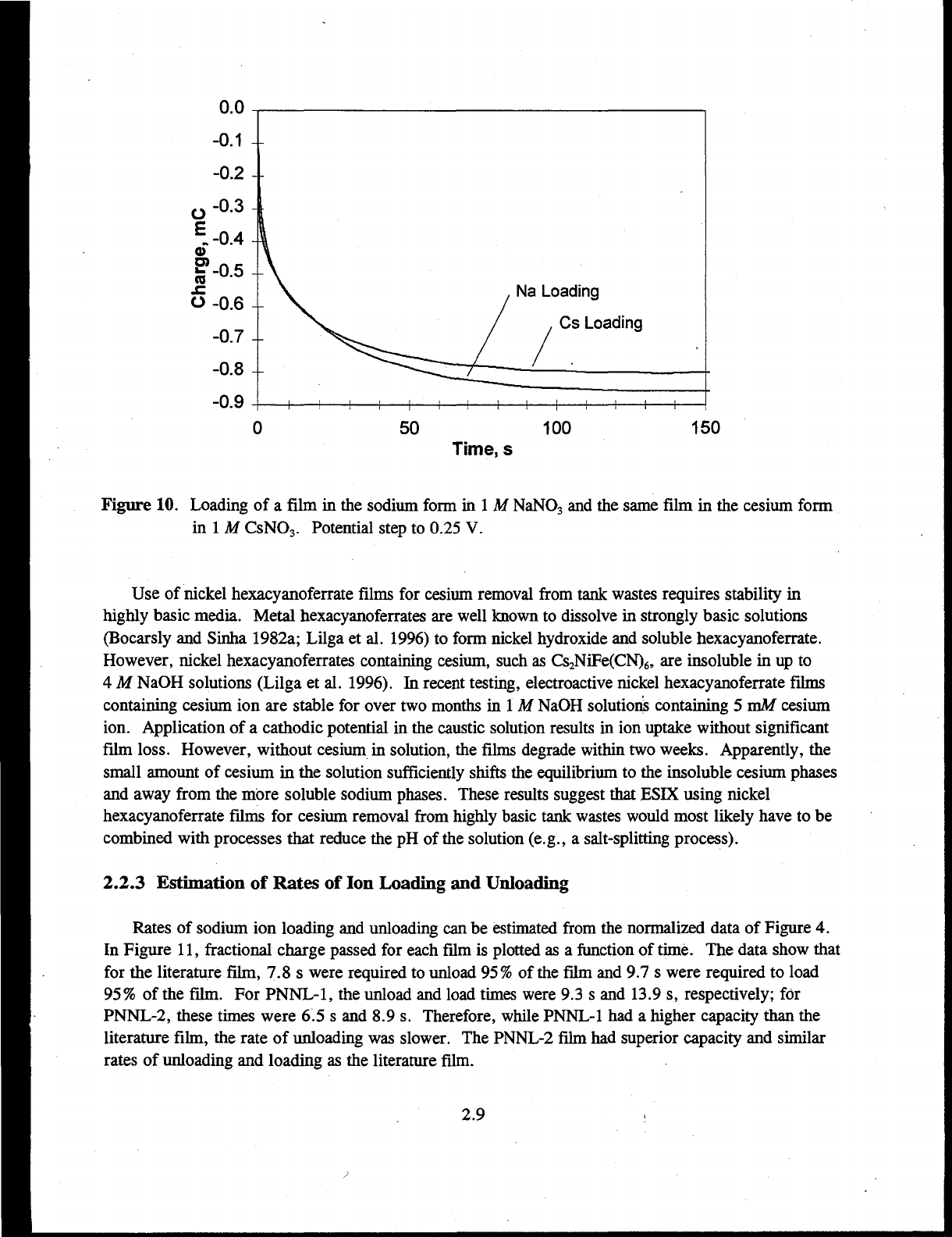
film in the cesium form, at an applied potential of 0.25 V is shown in Figure 10. Charge flows until
the film is completely loaded. Both sodium and cesium loaded into the film to nearly the same extent.
The potential step experiments more closely approximate how a process based on ESIX would operate.
2.8
Na Loading
Cs Loading
50
100
150
Time,
s
Figure 10. Loading of a film in the sodium form in 1 M NaNO
3
and the same film in the cesium form
in 1 M CsNO
3
. Potential step to 0.25 V.
Use of nickel hexacyanoferrate films for cesium removal from tank wastes requires stability in
highly basic media. Metal hexacyanoferrates are well known to dissolve in strongly basic solutions
(Bocarsly and Sinha 1982a; Lilga et al. 1996) to form nickel hydroxide and soluble hexacyanoferrate.
However, nickel hexacyanoferrates containing cesium, such as Cs
2
NiFe(CN)6, are insoluble in up to
4 M NaOH solutions (Lilga et al. 1996). In recent testing, electroactive nickel hexacyanoferrate films
containing cesium ion are stable for over two months in 1 M NaOH solutions containing 5 vaM cesium
ion. Application of a cathodic potential in the caustic solution results in ion uptake without significant
film loss. However, without cesium in solution, the films degrade within two weeks. Apparently, the
small amount of cesium in the solution sufficiently shifts the equilibrium to the insoluble cesium phases
and away from the more soluble sodium phases. These results suggest that ESIX using nickel
hexacyanoferrate films for cesium removal from highly basic tank wastes would most likely have to be
combined with processes that reduce the pH of the solution (e.g., a salt-splitting process).
2.2.3 Estimation of Rates of Ion Loading and Unloading
Rates of sodium ion loading and unloading can be estimated from the normalized data of Figure 4.
In Figure 11, fractional charge passed for each film is plotted as a function of time. The data show that
for the literature film, 7.8 s were required to unload 95% of the film and 9.7 s were required to load
95%
of the film. For
PNNL-1,
the unload and load times were 9.3 s and 13.9 s, respectively; for
PNNL-2, these times were 6.5 s and 8.9 s. Therefore, while PNNL-1 had a higher capacity than the
literature film, the rate of unloading was slower. The PNNL-2 film had superior capacity and similar
rates of unloading and loading as the literature film.
2.9

0)
a.
E?
re
£
o
"o
c
o
icti
u.
0.8
-
0.6
-
0.4
-
0.2
-
0.0-
f
f\\
Literature
/
/ \ PNNL-1
-
//
i
•
II
1
-
-
-I
*—\
1 1 1 1 1
\
\
\
\
\
\
\
\
PNNL-1
\\
/ /
Literature
\
X/ / PNNL-2
i—i—i
2
^ r^i i r
10
15
20
Time,
s
25 30
35
Figure 11. Normalized charge
as
a
function
of
time
for
three different film preparations (from cyclic
voltammetry
in
1
M
NaN0
3
)
Another reported method (Humphrey
et
al. 1984; Murray 1984)
to
estimate
the
rate
of
diffusion
through the film
is to
use chronocoulometry and the integrated Cottrell equation (Eq.
4) to
determine
c
=
~-'A
(4)
an apparent diffusion coefficient,
D
m
(C =
charge
in
Coulombs;
n =
equivalents
of
charge passed;
F
=
Faraday constant;
A =
surface area
in
cm
2
; C
o
*
=
concentration
of
electroactive film
in
moles/cm
3
). The charge passed
in a
chronocoulometry experiment
in
which
a
film was loaded with
sodium
ion
at
0.25
V
then unloaded
at
0.50
V is
plotted
as a
function
of
time
in
Figure
12.
This
experiment was conducted
in
0.5
M
Na
2
SO
4
on
a
0.65-cm-diameter electrode. The film was prepared
by
the
literature method. The total charge passed was 1.57 mC during
the
load step
and 1.55 mC
during the unload step, corresponding
to
an
average surface coverage
of
4.9
x
10"
8
moles/cm
2
.
The apparent diffusion coefficient
is
determined from
a
plot
of
charge
as a
function
of
the square
root
of
time, shown
in
Figure 13
for
the unload step. The short-time data corresponds
to
the
condition
of semi-infinite diffusion
for
which the Cottrell equation
is
valid. Using
the
slope
of
the data from
20
to 50% loading,
D
m
for
unloading the film
is
calculated
to
be
1.5 x
10"
n
cm
2
/s.
A
similar analysis
of
cathodic chronocoulometry results gives
a D
m
of
8.2
x
10"
12
cm
2
/s
for
sodium ion uptake. These
diffusion coefficients
are
similar
to
those reported
by the
Bocarsly group (Humphrey
et
al.
1984).
The
difference
in
D
#
for
loading and unloading
is
thought
to
be
due
to
solvent exchange processes
(Humphrey
et
al.
1984; Lasky and Buttry 1988).
2.10

o
E
<D
W
CO
CO
Q.
0)
S?
CO
o
0.0
-
-0.4-
-0
8 -
-1.2-
-1
fi -
I
I Load
1 (0.25 V)
\
—i—i—i—i—i—I—i—i—i—
r
Unload
(0.50 V)
-i—i—i—i—i—i—i—
50 100
Time,
s
150
200
Figure 12. Potential step loading (0.25 V) and unloading (0.50 V)
of a
film prepared by the literature
method
o
of
CO
O
1.4
-
1.2
-
1.0
-
0.8
-
0.6-
0.4
-
0.2-
0.0-
-
I
-
/
I
L—i 1 1 1 1 1 1 1 1
0.0
2.0 4.0 6.0
Time
1
*,
sec
1/2
8.0
10.0
Figure 13. Cottrell plot for unloading sodium from
a
film prepared by the literature method
2.11

2.2.4 Film Characterization Using Raman Spectroscopy
Development of a process based on ESIX technology will require use of high surface area
electrodes. Associated with large electrodes are the problems of current and potential control that must
be accounted for in the engineering design of the electrochemical reactor. An issue with electroactive
films is whether redox reactions occur homogeneously or in islands on the electrode. Homogeneous
redox reactions are desirable for predictable kinetics and process control and for efficient use of the
electrode area.
The results reported here indicate that Raman spectroscopy is a sensitive probe of the oxidation
state of the film. This technique is a good diagnostic tool for in situ investigations of the behavior of
metal hexacyanoferrate films during redox reactions and should give information about mechanisms of
film deactivation or loss. When a literature film is fully reduced with an applied potential of -111 mV,
two low wavenumber cyanide stretching modes are evident at 2103 cm"
1
and 2151 cm
1
, corresponding
to the ferrocyanide oxidation state (Figure 14). As the applied potential is made more anodic, the film
is observed to become increasingly oxidized. The film is almost completely in the ferricyanide form
(peak at 2186 cm"
1
) at an applied potential of 778 mV as shown in Figure 14. Ferro- and ferricyanide
have been distinguished on potential cycling of films with thicknesses as low as about 100A (10 unit
cells thick).
c
i
i i I
i
; I
1900 2000 2100 2200 2300
Raman Shift, cm'
1
2400
Figure 14. Raman spectra of hexacyanoferrate films on a 500-/an-diameter nickel disk electrode as a
function of applied potential
2.12

Imaging Raman spectroscopy shows that the thin film redox reactions occur uniformly across the
film rather than in isolated regions. Raman images of a 750-jtm-long by 30-/xm-wide region of film
were obtained as oxidation was carried out electrochemically (Figure 15). As oxidation occurred, the
spatially uniform growth of ferricyanide species was observed. This is the first time that spatial
uniformity of a thin film redox reaction has been demonstrated in situ. These results are important for
the design of a practical ion separation system and in maintaining as uniform a current distribution as
possible at a high surface area electrode.
2.2.5 Scale-up Considerations
In FY 1997, a bench-scale system will be designed, constructed, and tested. Thus some scale-up
issues were addressed this year to prepare for the FY 1997 activities. The scale-up parameters that
were considered included electrode surface area requirements, electrode materials, cell control, cell
configuration (i.e., divided versus undivided), mode of operation (i.e., once-through versus batch
recycle), and recommended available reactor systems. Electrosynthesis Company, Inc. was asked to
assist in addressing these issues. The assumptions, calculations, and conclusions resulting from this
study are given in the Appendix. The major assumptions and conclusions are summarized below.
The major assumptions used in addressing the scale-up issues are as follows:
1.
The cesium concentration in the waste is 0.5 vaM.
2.
A uniform surface loading of 10"
7
moles/cm
2
of CsNiFe(CN)
6
should be active in the Cs insertion
process.
3.
The volume of effluent to be treated by the described cells is 10 L/h.
4.
The process objective is to remove 99% of the Cs (decontamination factor of 100).
For these assumptions, required electrode surface areas were similar when based on both ion
exchange capacity and mass transport considerations. (If initial cesium concentrations are lower than
those assumed here, for example for Hanford K-basin waste, the mass transport considerations become
more important). This suggests that both are important to consider when designing the scaled-up
system. Additionally, the required electrode surface areas were such that a three-dimensional, high
surface area electrode configuration is essential.
For the given application, commercially available nickel foam and nickel felt materials are
available. The nickel felt materials typically have specific surface areas at least a factor of 10 higher
than the foams. However, felts have random, closed packed structures that can lead to non-uniform
flow. High surface area nickel foams were recommended as the preferred electrode material. The
commercially available specific electrode areas for such foams range from approximately 35 cnrVcm
3
to 90 cnrVcm
3
.
2.13

co
2103 2151 2186
Raman Shift [cm-
1
]
Figure 15. Imaging Raman spectra of a literature film on a nickel wire showing spatially homogeneous
redox reactions
2.14

Further investigation of controlled current operation was recommended in addition to the assumed
potential control mode of operation because when a current is passed through a cell, the most readily
occurring anode and cathode reactions will take place. Based on experimental evidence and ion
exchange characteristics of ferrocyanide materials, when a cathodic current is passed through a nickel
ferricyanide film in a solution containing Na
+
and Cs
+
, Cs
+
should preferentially be taken up by the
film, and thus should be the most readily occurring reaction. To prevent excessive hydrogen or
oxygen evolution when the electrode has become fully charged or discharged, it was recommended that
either the electrode be oversized or a charge limit be put into the control.
Both batch recycle and once-through modes of operation were considered. Based on calculations,
both modes of operation were found to be applicable and practical options. Additionally, for this
application there was no advantage to using a divided cell versus an undivided cell; therefore, use of an
undivided cell was recommended. Numerous commercially available reactors were recommended for
this application.
2.15

3.0 Conclusions
This research has demonstrated the viability of ESIX for metal ion separations. Ion loading and
unloading is easily controlled by modulating the electrode potential. The use of metal hexacyano-
ferrates, which are known cesium ion exchange materials, is expected to give high selectivity for
cesium over sodium. Films are relatively easy to prepare, but modifications to the reported procedures
can generate films with significantly improved capacity and stability. The best films prepared to date
have almost twice the capacity of previously reported films and lose less than 20% of their capacity
after 2000 cycles. The ability to cycle through many load/unload cycles is important to the
development of a practical process since the absolute capacity of a film on an electrode surface is much
less than the capacity of a standard ion exchange column. Bench-scale testing is needed to determine
whether cycle time and throughput are sufficient to allow ESIX to perform on a par with standard
technologies, such as conventional ion exchange. If so, use of a regenerable material and the
minimization of secondary waste will be significant advantages in favor of the ESIX process.
Ongoing research encompasses investigating the preparation of films with higher capacity and
stability, determining the selectivity of cesium ion uptake, and designing and testing appropriate flow
reactor systems for bench-scale research. The use of Raman spectroscopy to probe film loss and
deactivation mechanisms is also continuing and a more-detailed discussion of these results will be
published in the future. Ultimately, cesium removal from real waste streams using a flow system will
be tested.
3.1

4.0 References
Andrieux, C. P. and J. M. Saveant. 1980. "Electron Transfer Through Redox Polymer Films."
Journal of Electroanalytical Chemistry 111:377.
Bacskai, J., K. Martinusz, E. Czirok, G. Inzelt, P. J. Kulesza, and M. A. Malik. 1995. "Polynuclear
Nickel Hexacyanoferrates: Monitoring of Film Growth and Hydrated Counter-cation Flux/Storage
during Redox Reactions." Journal of Electroanalytical Chemistry
385:241.
Barton, G. B., J. L. Hepworth, Jr., E. D. McClanahan, R. L. Moore, and H. H. van Tuyl. 1958.
"Chemical Processing Wastes — Recovering Fission Products." Industrial and Engineering Chemistry
102:212.
Bocarsly, A. B. and S. Sinha. 1982a. "Chemically Derivatized Nickel Surfaces: Synthesis of a New
Class of Stable Electrode Interfaces." Journal of the Electroanalytical Chemistry and Interfadal
Electrochemistry 137:157.
Bocarsly, A. B. and S. Sinha. 1982b. "Effects of Surface Structure on Electrode Charge Transfer
Properties. Induction of Ion Selectivity at the Chemically Derivatized Interface." Journal of the
Electroanalytical Chemistry and Interfacial Electrochemistry 140:167.
Bridger, N. J., C. P. Jones, and M. D. Neville. 1991. "Electrochemical Ion Exchange." Journal of
Chemical Technology and Biotechnology 50:469.
Gephart, R. E. and R. E. Lundgren. 1995. "Hanford Tank Clean up: A Guide to Understanding the
Technical Issues." PNNL-10773, Pacific Northwest National Laboratory, Richland, Washington.
Haight, S. M. and D. T. Schwartz. 1995. "In situ Imaging Raman Spectroscopy of Electrochemically
Deposited CuSCN." Journal of the Electrochemical Society 142:L156.
Harjula, R., J. Lehto, E. H. Tusa, and A. Paavola. 1994. "Industrial Scale Removal of Cesium with
Hexacyanoferrate Exchanger — Process Development." Nuclear Technology 107:272.
Humphrey, B. D., S. Sinha, and A. B. Bocarsly. 1984. "Diffuse Reflectance Spectroelectrochemistry
as a Probe of the Chemically Derivatized Electrode Interface. The Derivatized Nickel Electrode."
Journal of Physical Chemistry 88:736.
Humphrey, B. D., S. Sinha, and A. B. Bocarsly. 1987. "Mechanisms of Charge Transfer at the
Chemically Derivatized Interface: The Ni/[Ni
n
(CN)Fe
n/ra
(CN)
5
]
2/1
- System as an Electrocatalyst."
Journal of Physical Chemistry 91:586.
4.1

Ikeshoji, T. 1986. "Separation of Alkali Metal Ions by Intercalation into a Prussian Blue Electrode."
Journal of the Electrochemical Society 133:2108.
Itaya, K, I. Uchida, and V. D.
Neff.
1986. "Electrochemistry of Polynuclear Transition Metal
Cyanides: Prussian Blue and Its Analogues." Accounts of Chemical Research 19:162.
Jones,
C. P., M. D. Neville, and A. D. Turner. 1992. "Electrochemical Ion Exchange" in
Electrochemistry for a Cleaner Environment, D. Genders and N. Weinberg, Eds., The Electrosynthesis
Company Inc., East Amherst, New York, p. 207.
Koukim, V., J. Rais, and B. Million. 1964. "Exchange Properties of Complex Cyanides — I. Ion
Exchange of Caesium on Ferrocyanides;" Journal of Inorganic and Nuclear Chemistry
26:1111.
Kurath, D. E., L. A. Bray, K. P. Brooks, G. N. Brown, S. A. Bryan, C. D. Carlson, K. J. Carson, J.
R. DesChane, R. J. Elovich, and A. Y. Kim. 1994. Experimental Data and Analysis to Support the
Design of an Ion-Exchange Process for the Treatment ofHanford Tank Waste Supernatant Liquids,
PNNL-10187, Pacific Northwest National Laboratory, Richland, Washington.
Lasky, S. J. and D. A. Buttry. 1988. "Mass Measurements Using Isotopically Labeled Solvents
Reveal the Extent of Solvent Transport during Redox in Thin Films on Electrodes." Journal of the
American Chemical Society 110:6258.
Laviron, E. 1980. "A Multilayer Model for the Study of Space Distributed Redox Modified
Electrodes." Journal of Electroanalytical Chemistry
112:1.
Lehto J. and R. Harjula. 1987. "Separation of Cesium from Nuclear Waste Solutions with
Hexacyanoferrate(II)s and Ammonium Phosphomolybdate." Solvent Extraction and Ion Exchange
5:343.
Lehto, J., R. Harjula, and J. Wallace. 1987. "Absorption of Cesium on Potassium Cobalt
Hexacyanoferrate(H)" Journal of Radioanalytical and Nuclear Chemistry 111:297.
Lilga, M. A., R. T. Hallen, E. V. Alderson, M. O. Hogan, T. L. Hubler, G. L. Jones, D. J.
Kowalski, M. R. Lumetta, W. F. Riemath, R. A. Romine, G. F. Schiefelbein, and M. R. Telander.
1996.
Ferrocyanide Safety Project. Ferrocyanide Aging Studies Final Report, PNNL-11211, Pacific
Northwest National Laboratory, Richland, Washington. .
Loewenschuss, H. 1982. "Metal-Ferrocyanide Complexes for the Decontamination of Cesium from
Aqueous Radioactive Waste." Radioactive Waste Management 2:327.
Loos-Neskovic, C. and M.
Fedoroff.
1984. "Recovery of Silver from Solutions by Fixation on
Insoluble Ferrocyanides." Annales de Chimie Science des Materiaux 9:609.
4.2

Loos-Neskovic, C. and M.
Fedoroff.
1987. "Exchange Mechanisms of Silver on Nickel and Zinc
Ferrocyanides." Solvent Extraction and Ion Exchange 5:757.
Loos-Neskovic, C. and M.
Fedoroff.
1988. "Exchange Mechanisms of Alkali Ions on Zinc
Ferrocyanides." Reactive Polymers 7:173.
Loos-Neskovic, C. and M.
Fedoroff.
1989a. "Fixation Mechanisms of Cesium on Nickel and Zinc
Ferrocyanides." Solvent Extraction and Ion Exchange
7:131.
Loos-Neskovic, C. and M.
Fedoroff.
1989b. "Decontamination of Liquid Nuclear Wastes by Fixation
of Radioactive Elements on Nickel and Zinc Ferrocyanides." Radioactive Waste Management and the
Nuclear Fuel Cycle 11:347.
Loos-Neskovic, C, M.
Fedoroff,
E. Gamier, and P. Gravereau. 1984. "Zinc and Nickel
Ferrocyanides: Preparation, Composition, and Structure." Talanta 31:1133.
Loos-Neskovic, C, M.
Fedoroff,
and G. Revel. 1976a. "Use of Radioisotopes for Retention Study
on Nickel Ferrocyanide." Journal of Radioanalytical Chemistry 30:533.
Loos-Neskovic, C, M.
Fedoroff,
and G. Revel. 1976b. "Influence of Sodium Content of Nickel
Ferrocyanides on the Retention of Alkaline Ions." Radiochemistry and Radioanalytical Letters
26(1):
17-26.
Murray, R. W. 1980. "Chemically Modified Electrodes." Accounts of Chemical Research 13:135.
Murray, R. W. 1984. "Chemically Modified Electrodes." in Electroanalytical Chemistry, Vol. 13, A.
J. Bard, Ed., Marcel Dekker, Inc., New York.
PNNL. 1996. Efficient Separations and Processing Crosscutting Program 1996 Technical Exchange
Meeting, PNNL-SA-27105, Pacific Northwest National Laboratory, Richland, Washington.
Prout, W. E., E. R. Russell, and H. J. Groh. 1965. "Ion Exchange Absorption of Cesium by
Potassium Hexacyanocobalt(II)Ferrate(II)." Journal of Inorganic and Nuclear Chemistry 27:473.
Schneemeyer, L. F., S. E. Spengler, and D. W. Murphy. 1985. "Ion Selectivity in Nickel
Hexacyanoferrate Films on Electrode Surfaces." Inorganic Chemistry 24:3044.
Sinha, S., B. D. Humphrey, and A. B. Bocarsly. 1984. "Reaction of Nickel Electrode Surfaces with
Anionic Metal-Cyanide Complexes: Formation of Precipitated Surfaces." Inorganic Chemistry 23:203.
Tusa, E. H., A. Paavola, R. Harjula, and J. Lehto. 1994. "Industrial Scale Removal of Cesium with
Hexacyanoferrate Exchanger — Process Realization and Test Run." Nuclear Technology 107:279.
4.3

Appendix
Contractor Report
Electrically Controlled Ion Exchange
Dr. David Genders
Electrosynthesis Company, Inc.
72 Ward Road
Lancaster, NY 14086
A.I

REPORT TO BATTELLE PACIFIC NORTHWEST
PRELIMINARY PROBLEM ASSESSMENT
Assumptions
1.
The concentration of Cs
+
in the waste is 0.5 mM.
2.
A surface loading of CsNiFe(CN)6 which is uniform and at least a fraction of the film
equivalent to « 10"
7
moles cm"
2
should be active in the Cs
+
insertion process; this is
equivalent to « 200 monolayers or « 0.04 um.
3.
The volume of effluent to be treated by the cells described is 10 I/hour.
4.
The process objective is to remove 99% of the Cs
+
(ie. a conversion of 0.99).
The electrode areas/cell sizes are likely to increase linearly with the Cs
+
concentration and the
volume/unit time of waste to be treated. Also the electrode area required will be inversely
proportional to the loading of CsNiFe(CN)6. In general, each order of magnitude change in the
target level for removal of Cs
+
will change the required electrode area by a substantial factor (1.5
to 2, see below).
Preliminary comments
Surface area
Two considerations could determine the surface area of electrode required in the cell.
These are the mass transport of Cs
+
to the electrode surface and the ion exchange capacity of the
nickel ferrocyanide film.
In electrochemical terms, the ion exchange capacity of the surface coating would
normally be expressed as a charge density; a film containing 10"
7
moles cm"
2
has a charge
density of 10 mC cm"
2
. The minimum charge (ie. assuming 100% current efficiency) required to
remove 0.5 mM Cs
+
from 10 litres is 500 C. Therefore the minimum surface area needed is 5 x
10
4
cm
2
(ie. 5 m
2
).
No electrode reaction can occur above the rate at which the reactant reaches the electrode
surface. Hence, one can calculate the minimum electrode area from the viewpoint of mass
transport, hi fact, in a batch reactor under mass transport control the conversien is given by the
equation
conversion = c(t)/c(0) = exp -k
m
At/V
(1)

where c(t) and c(0) are the concentrations of reactant at time t and before electrolysis
respectively, k
m
the mass transport coefficient, A the electrode area, V the volume of waste to be
treated and t is the electrolysis time (all equations used in this report are taken from the book by
F.C.
Walsh "A First Course in Electrochemical
Engineering"
1
available from the Electrosynthesis
,-3
-1
'
4
cm and t = 1 hour = 3.6
Co).
In a reasonable cell design k
m
= 10" cm s" and here V = 101 = 10
x 10
3
s. Hence to reduce, the Cs
+
level to 1 % of the system input ( a conversion of 0.99) requires
A= -2.3x(-2)xlO
4
= 1.3xl0
4
cm
2
=1.3m
2
10"
3
x3.6xl0
3
To increase the conversion to 0.999 would increase the area requirement by a factor of
1.5 while a 0.9 conversion would halve the area needed. It should be stressed that the these areas
are independent of the absolute Cs
+
concentration (see above equation) because the current
density will increase linearly with concentration (the available electrode area effectively works
harder).
It can be seen that the two areas calculated from consideration of ion exchange capacity
and mass transport appear not dissimilar and hence both ion exchange capacity and mass
transport could be factors in cell design considerations. It is probable that the limiting factor is
the nickel ferricyanide loading and we would therefore stress the importance of achieving at least
the target loading.
Certainly the areas estimated from both ion exchange capacity and mass transport
considerations are so large that no practical cell could employ a flat plate electrode. A three
dimensional electrode will be essential.
Three dimensional electrode materials
Three dimensional electrodes have been fabricated from beds of spheres and other
particles, fibers, metal wools, stacks of meshes, foams, felts etc. In this project, we are looking
for materials which give both a high specific electrode area (real electrode area per unit volume)
and good mass transport. Also, since it is necessary to coat the surface with nickel ferrocyanide,
it is essential to select materials which can be uniformly and adequately coated. Because of cost,
it is not reasonable to use precious metals and our proposals are limited to nickel and either
carbon or base metal supports.
Foams are attractive materials which have been successfully employed as electrodes by
several groups. They have a uniform structure and a high porosity; hence it should be possible to
coat them. Moreover, they have a low electrical resistance and give satisfactory mass transport
coefficients. Nickel foams are available and have been used as electrodes (eg, Langlois et al., J.
Applied Electrochem., 19 (1989) 43, 51 and 736, Tissot el al 26 (1996) 211). Reticulated
vitreous carbon electrodes are perhaps more common electrode materials (eg, Pletcher et al, J.
Applied Electrochem., 21 (1991) 659 and 667 and 23 (1993) 82). Some properties relevant to
this project are summarized in table 1 and it can be seen that the properties of Ni foam and
reticulated vitreous carbon are similar. For example it can be seen that the real area of 5 x 10
4

cm for the treatment of 10 litres could be achieved with « 500 - 1000 cm of 100 ppi material.
A typical thickness of foam in electrolytic applications is 1.2 cm and hence a piece of foam 400 -
800 cm
2
would suffice. The Ni foams are available from the Electrosynthesis Co and also from
Sorapec in France. Both Ni foam and reticulated vitreous carbon have been used commercially in
the Retec technology.
Ni and carbon felts are also available from Sorapec and the Electrosynthesis Co and these
have specific surface areas at least a factor of ten higher than the foams. Certainly, values of
k
m
A
e
determined electrochemically are higher by a factor of ten for the felts than the foams and
this appears to enhance cell performance substantially. Moreover Ni felt (Electrochim Acta 32
(1987) 1303) and carbon felt (Porocell technology, pilot and laboratory scale work by the
Electrosynthesis Co and others) have been used in electrolytic cells. The problem with felts is
that they have a random, close packed structure and it can be difficult to achieve uniform
pumping rates through electrodes of any size. It is usually particularly difficult to coat such
structures uniformly and we believe that it would be much more difficult to produce an
acceptable coating of nickel ferrocyanide on the felts compared to the foams.
The foams and felts would be our preferred cathode materials although there are others
which could be tested. For example, Olin now market a three dimensional Ti material, known as
Tysar* which it may be possible to Ni plate; they are also believed to be developing a Ni (as well
as steel) based structure of this type (specific surface areas 90 - 500 cm
2
cm
3
). Sintered Ni with
various porosities are used in the battery industry and it is also possible to consider stacked mesh
electrodes or metal wools.
Clearly, the successful coating of any material with nickel ferricyanide is a requisite to
application in the electrolytic cell and the choice of cathode will depend on the coating
technology which will be developed.
CELL CONTROL STRATAGEES
Controlled potential vs controlled current
The proposal EM-50 seems to assume that the potential of the nickel ferri/ ferrocyanide
coated electrode will need to be controlled even in the scaled up technology. This would be very
expensive and appears at first sight to be unnecessary. When a current is passed through a cell,
the most readily occurring anode and cathode reaction take place. On the basis of the
voltammetry reported, there is little doubt that when a cathodic current is passed through a nickel
ferricyanide coating in a solution of Na
+
/Cs
+
, it is the Cs
+
which will go into the film. Moreover,
the reaction has another desirable feature; in a three dimensional electrode, the uniformity of the
reaction can be problem. This will not be the case here because once the film in one area of the
electrode is filled with Cs
+
, the local current will drop to zero and the Cs
+
will insertion in the
next available zone; the insertion reaction zone will move through the thickness of the electrode.
Hence, it would be possible to operate with relative thick foam electrodes, where in other
situations, much of the thickness would be inactive due to IR drop. We recommend strongly
that controlled current operation be investigated.

The preferred constant current can be determined experimentally, for example, by
voltammetry. The only likely hazard is hydrogen/oxygen evolution if electrolysis is allowed to
continued when the electrode has become fully charged/discharged with Cs
+
. Then, either the
extreme of potential or the gas evolution could damage/disrupt the nickel ferri/ ferrocyanide
film. This could be avoided by oversizing the electrode or putting a charge limit into the control
regime.
Divided vs undivided cell
There is no compelling reason to include a membrane or porous separator in the cell
design. During removal of the Cs
+
from solution the counter electrode reaction will probably be
oxygen evolution and during discharge of the nickel ferrocyanide film it will be hydrogen
evolution. Neither will interfere with the working electrode chemistry and Cs
+
will itself not
oxidize/reduce. Other trace components of the waste stream may be electroactive but this may
not be regarded as a disadvantage. Moreover, the charge put into the waste stream is small
because of the low Cs
+
. Since undivided cells are cheaper and more flexible, we recommend
the use of undivided cells.
The current from 1 cm
3
of foam may be estimated from the equation
I =
(2)
For a 0.5 mM (5 x 10~
7
mol cm"
3
) solution of Cs
+
and 100 ppi foam (for data see table 1), this
current is « 10 mA. Hence, in the designs outlined below, the current density on the counter
electrode will be 10-50 mA cm"
2
. This is a quite normal value in effluent treatment cells. In all
cell configurations, an appropriate counter electrode material will need to be selected. It will act
alternately as anode and cathode during load/release of Cs
+
and this prevent the use of some
materials. The choice might depend on the pH and composition of the waste.
Solution - once through cell or batch recycle operation
The cell may be operated either in the once through mode where the required depletion is
achieved in a single pass or by recycling a batch through the cell.
Once through operation
The solution flow is fixed at 10 liters/hour or 3.6 cm
3
s"
1
. For a reasonable mean linear
flow rate, say 1 cm s"
1
, this fixes the area of the electrolyte chamber, A
x
, at 3.6 cm
2
or 3 cm x 1.2
cm using standard materials. Assuming mass transport control, the electrode length, L, required
for 99 % removal is given by
logc
out
/cin
(3)

where Q
v
is the volumetric flow rate. Substituting values (see assumptions and table 1) into the
equation, gives an electrode length of « 50 cm for a conversion of 0.99 for a mass transport
controlled reaction. In fact, this gives an electrode volume of only 180 cm
3
. This is insufficient
to provide the area of nickel ferricyanide to accept all the Cs
+
in solution. The calculation above
suggested a requirement of 500 - 1000 cm
J
from this point of view. Changing the electrode
thickness or width to increase the electrode volume will decrease the mean linear flow rate and
hence decrease the mass transport coefficient. Even so an electrode 1.2 cm thick x 10 cm wide x
100 cm long should lead to a 99 % removal with some safety margin. This is an unusual shape
for a commercial cell but could readily be constructed.
Batch recycle operation
In this mode of operation, the 10 liters of effluent would be placed in a reservoir and this
solution would be recycled continuously through the cell. This is a convenient way to carry out
most experiments in the laboratory since it removes the relationship between electrode
dimensions and flow rate. The solution may therefore be circulated rapidly giving a much
enhanced mass transport coefficient. It also "fits" commercial cell designs. The disadvantage is
that unless the intention is to carry out batchwise the waste treatment process, it is a poor model
for scale up.
,-3
It is likely that a mass transport coefficient of 5 x 10 cm s can be achieved in, for
example, an MP or ElectroSyn cell with a foam cathode. Equation (1) would apply to this
experiment giving an area requirement for a mass transport controlled reaction would be only 2.5
x 10
3
cm
2
or a piece of foam with a volume « 30 cm
3
. Here, therefore, the factor determining
the electrode area would clearly be the surface loading of nickel ferricyanide; the area estimated
above was 5 x 10
4
cm
2
equivalent to a foam volume of« 600 cm
3
. Allowing some safety margin
would suggest w 1000 cm
3
.
Because of the dominance of the ion exchange capacity in determining electrode size,
there appears to be unusually little disadvantage in operating in the once through mode. We
therefore recommend the use of once through designs although in preliminary flow cell
experiments there is some attraction in employing a smaller volume of waste (say 1 liter) and a
small commercial cells in the batch recycle mode.
RECOMMENDED REACTOR DESIGNS
For each of the recommended commercial reactors, advertising literature is attached. Only
specific comments are attached. Throughout the suggested electrode material is nickel foam
although the alternatives described above should also be tested in at least one cell provided they
can be satisfactorily coated with nickel ferricyanide.
1.
Electrocell AB
The electrode volume and length would be readily achieved with an ElectroSyn reactor
with 5 undivided cells in series with their electrolyte chambers fitted with 4 mm thick foam and a

polymer mesh to avoid shorting of the cell. These cells are not routinely marketed with foam
electrodes but it is possible to replace the turbulence promotes with foam contacted through a
back plate. Estimated cost $6,000 for an undivided cell with projected area of 0.4 m
2
.
2.
RetecCell
This is an upgraded tank cell design which is certainly adequate at the 10 liter scale but
may not be suitable for substantial scale up or remote operation. We would suggest the RETEC
6. Cost: $7300. It is probably necessary to use non standard counter electrodes (the DSA anodes
may not be stable as cathodes).
3.
Porocell
This is normally an undivided tubular cell with most of the cylinder volume filled with a
carbon felt. A standard cell has the dimensions of 50 cm long x 18 cm diameter which would
have the required ion exchange capacity if packed with uniformly coated carbon felt or Ni foam.
Cost: $6,400 for a 1 m
2
cell and $4,500 for a 0.5 m
2
cell.
4.
Aquanautics Cell
This is another parallel plate reactor which could be modified to take a Ni foam electrode.
A standard ABC-250 cell stack with three foam working electrodes in series would give the
required electrode volume and length. Cost: $ 3,500 for a cell containing 250 cm
2
projected
electrode area.
5. Purpose Built Cells
We would also wish to consider the design and fabrication of purpose built cells with
cylindrical or rectangular geometries. Commercial cells are generally designed for processes
where mass transport is a critical consideration; with the slow flow rates which fulfill the process
requirements, it should be straightforward and cheap to develop purpose built cells.
We would stress that the employment of larger cells (1 m
2
) when the program is extended
to higher treatment rates will be cheaper per unit volume of waste. On the other hand, further
scale up is achieved by increasing the number of cells and the cell investment cost will then be
almost proportional to the number of cells.

specific electrode area/cm
2
cm"
3
mass transfer coefficientVcm s"
1
Ni foam
45ppi
60 ppi
100 ppi
35 ±9
58 + 8
92+10
RVC
Table 1
1.4 xlO"
3
1.3 xlO"
3
1.5 xlO"
3
0.9 xlO"
3
1.1 xlO"
3
1.2 xlO"
3
Specific surface areas, A
e
, estimated from pressure drop measurements and
mass transfer coefficients, k^ taken from limiting current measurements.
Data from J. Applied Electrochem., 19 (1989) 43, 51 and J. Applied
Electrochem., 21 (1991) 659. f at a mean linear flow rate of
1
cm s'
1
30 ppi
60 ppi
100 ppi
24 + 9
32 ±10
67 ±3

PNNL-11441
UC-701
Distribution
OFFSITE
2 DOE/Office
of
Scientific
and
Technical Information
Dr. Moses Attrep,
Jr.
Los Alamos National Laboratory
P.O.
Box 1663, MS J514
Los Alamos,
NM
87545
Ms.
Debra
A.
Bostick
Oak Ridge National Laboratory
P.O.
Box
2008
Oak Ridge,
TN
37831-6201
Professor Daryle Busch
University
of
Kansas
Department
of
Chemistry
Lawrence,
KS
66045
Professor Greg Choppin
Florida State University
Department
of
Chemistry
600 West College Avenue
Tallahassee,
FL
32306
Ms.
Julie
E.
Connor
U.S.
Department
of
Energy
Idaho Operations Office
765 Lindsay Blvd., Mailstop
1225
Idaho Falls,
ID
83401
Dr. Dirk Gombert
Lockheed Martin Idaho Technologies
P.O.
Box 1625,
Mail Stop 3875
Idaho Falls,
ID
83415
Mr. Kurt Gerdes
U.S.
Department
of
Energy
Program Manager
Efficient Separations
and
Processing
Office
of
Science
and
Technology
EM-53
CL
19901 Germantown Road
Germantown,
MD
20874
Mr. Scott Haight
University
of
Washington
Deptment
of
Chemical Engineering
Box 351750
Seattle,
WA
98195-1750
Dr. Jerry
L.
Harness
U.S.
Department
of
Energy
Oak Ridge Operations Office
P.O.
Box
2001, 3-MAIN
Oak Ridge,
TN
37831
Prof.
Dennis Kelsh
Gonzaga University
Department
of
Chemistry
E.
505
Boone
Ave.
Spokane,
WA
99258-0001
Prof.
KNona Liddell
Washington State University
Department
of
Chemical Engineering
Pullman,
WA
99164-2710
Mr. Phil McGinnis
Martin Marietta Energy Systems
4500-N, MS-6273
P.O.
Box
2008
Oak Ridge,
TN
37831
Distr.l

PNNL-11441
UC-701
Dr. Don Orth
124 Vivion Drive
Aiken, SC 29803
Dr. Martin Steindler
Argonne National Laboratory
9700 South Cass Avenue
Argonne, IL 60439
Dr. Dee Stevenson
3367 E. Bernada Drive
Salt Lake City, UT 84124
Dr. John Swanson
1318CottonwoodDr.
Richland,WA 99352
Dr. Ian R. Tasker
Waste Policy Institute
Quince Diamond Executive Center
555 Quince Orchard Road
Gaithersburg, MD 20878-1437
Dr. Major Thompson
Savannah River Technology Center
P.O.
Box 616
Aiken, SC 29802
Dr. Jack Watson
Oak Ridge National Laboratory
P.O.
Box 2008
Oak Ridge, TN 37831-6149
Dr. James Phelan
Sandia National Laboratories
P.O.
Box 5800, Mail Stop 0719
Albuquerque, NM 87185-0719
Dn J. A. Wright
U.S.
Department of Energy
Savannah River Operations Office
P.O.
Box A
Aiken, SC 29808
John Mathur
U.S.
Department of Energy
Office of Science and Technology
EM-53 CL
19901 Germantown Road
Germantown, MD 20874
Dr. John H. Kolts
U.S.
Department of Energy
Idaho Operations Office
765 Lindsay Blvd., Mailstop 1147
Idaho Falls, ID 83401
Dr. Ray Wymer
188A Outer Drive
Oak Ridge, TN 37831
Dr. Daniel T. Schwartz
University of Washington
Deptment of Chemical Engineering
Box 351750
Seattle, WA 98195-1750
Dr. J. David Genders
Electrosynthesis Company, Inc.
72 Ward Road
Lancaster, NY 14086-9779
Distr.2

PNNL-11441
UC-701
ONSITE
2 DOE Richland Operations Office
R. A. Pressentin K8-50
B.
M. Mauss K8-50
Lockheed Martin Hanford Company
J. N. Appel G3-21
Numatec Hanford Company
R. A. Kirkbride H5-27
rra
D.
K. Oestreich H9-10
SGN Eurisys Services Corporation
R.K. Biyani L5-31
24 Pacific Northwest National Laboratory
E. G. Baker
W. F. Bonner
G. N. Brown
J. L. Buelt
R. T. Hallen
W. L. Kuhn
D.
E. Kurath
J. P. LaFemina
M. A. Lilga (5)
R. J. Orth
M. E. Peterson
S. D. Rassat
S. C. Slate
T. L. Stewart
J. P. H. Sukamto
Technical Report
P8-38
K9-14
P7-25
P7-41
P8-38
K2-21
P7-20
K9-91
P8-38
K3-75
K2-47
P7-41
K9-14
K9-91
P7-41
Files (5)
Distr.3
