
Flex Duo System
Radio Control Equipment
Technical Manual
Part Number: 191-32000-M000 R00
November 2020
© Copyright 2020 Magnetek

Flex Duo Technical Manual
November 2020
Page 2
Page Intentionally Left Blank

Flex Duo Technical Manual
November 2020
Page 3
SERVICE INFORMATION
Service Information:
For questions regarding service or technical information contact:
1.866.MAG.SERV
(1.866.624.7378)
International Service
Outside the U.S. and Canada call 1.262.783.3500, press 3.
Locations:
Columbus McKinnon Corporation
Magnetek Office
N49 W13650 Campbell Drive
Menomonee Falls, WI 53051 USA
Telephone: 800.288.8178
E-mail: field.service@magnetek.com
Fax Numbers:
Main: 800.298.3503
Sales: 262.783.3510
Service: 262.783.3508
Canada Service Information
161 Orenda Road
Unit 1
Brampton, Ontario
L6W 1W3 Canada
Phone: 800.792.7253
Fax: 905.828.5707
416.424.7617 (24/7 Service pager)
Website
https://www.columbusmckinnon.com/magnetek
© 2020 Columbus McKinnon Corporation
All rights reserved. This notice applies to all copyrighted materials included with this product, including, but not
limited to, this manual and software embodied within the product. This manual is intended for the sole use of the
person(s) to whom it was provided, and any unauthorized distribution of the manual or dispersal of its contents is
strictly forbidden. This manual may not be reproduced in whole or in part by any means whatsoever without the
expressed written permission of the Columbus McKinnon Corporation.

Flex Duo Technical Manual
November 2020
Page 4
PRODUCT SAFETY INFORMATION
Magnetek, Inc. (Magnetek) offers a broad range of radio remote control products, control products, adjustable
frequency drives, and industrial braking systems for numerous industries including overhead lifting and mobile
hydraulics. This manual has been prepared by Magnetek to provide information and recommendations for the
installation, use, operation and service of Magnetek's material handling products and systems (Magnetek
Products). Anyone who uses, operates, maintains, services, installs or owns Magnetek Products should know,
understand and follow the instructions and safety recommendations in this manual for Magnetek Products.
The recommendations in this manual do not take precedence over any of the following requirements relating to
cranes, hoists and lifting devices:
• Instructions, manuals, and safety warnings of the manufacturers of the equipment where the radio system
is used
• Plant safety rules and procedures of the employers and the owners of facilities where the Magnetek
Products are being used
• Applicable local and national codes / laws, ordinances, standards and requirements such as OSHA and
CE
This manual does not include or address the specific instructions and safety warnings of these manufacturers or
any of the other requirements listed above. It is the responsibility of the owners, users and operators of the
Magnetek Products to know, understand and follow all of these requirements. It is the responsibility of the owner of
the Magnetek Products to make its employees aware of all of the above listed requirements and to make certain
that all operators are properly trained. No one should use Magnetek Products prior to becoming familiar with
and being trained in these requirements.
WARRANTY INFORMATION
For information on Magnetek’s product warranties by product type, please visit www.columbusmckinnon.com/
magnetek.

Flex Duo Technical Manual
November 2020
Page 5
Table of Contents
1 Introduction ....................................................................................................................................................... 7
2 Radio-Controlled Safety .................................................................................................................................... 8
2.1 Critical Installation Considerations............................................................................................................ 9
2.2 General ..................................................................................................................................................... 9
2.3 Persons Authorized to Operate Radio-Controlled Equipment .................................................................. 9
2.4 Safety Information and Recommended Training for Radio-Controlled Equipment Operators ................ 10
2.5 Transmitter Unit ...................................................................................................................................... 11
2.6 Pre-Operation Test ................................................................................................................................. 11
2.7 Batteries.................................................................................................................................................. 11
2.8 Changing Batteries ................................................................................................................................. 12
2.9 Battery Charger (Optional)...................................................................................................................... 12
2.9.1 Charging Cradle Top View ................................................................................................................. 13
2.9.2 Power Supply ..................................................................................................................................... 13
2.9.3 Charging............................................................................................................................................. 14
2.9.4 Retaining Belt ..................................................................................................................................... 14
2.9.5 Wall Mounting the Charger................................................................................................................. 15
3 General System Information............................................................................................................................ 16
3.1 General Operation .................................................................................................................................. 16
3.2 Transmitter.............................................................................................................................................. 17
3.2.1 External Illustration............................................................................................................................. 17
3.2.2 Internal Illustration .............................................................................................................................. 18
3.3 Receiver.................................................................................................................................................. 19
3.3.1 External Illustration............................................................................................................................. 19
3.3.2 Internal Illustration .............................................................................................................................. 20
3.3.3 Output Relay Contact Diagrams......................................................................................................... 21
4 Function Settings ............................................................................................................................................ 22
4.1 Transmitter Settings................................................................................................................................ 22
4.1.1 Transmitter Firmware Version ............................................................................................................ 22
4.1.2 Transmitter Channel Settings............................................................................................................. 22
4.1.3 Remote Pairing................................................................................................................................... 23
4.1.4 Transmitter Output Power Settings .................................................................................................... 27
4.1.5 Transmitter Inactivity Timer Settings .................................................................................................. 27
4.1.6 Transmitter Start Function Settings.................................................................................................... 28
4.1.7 Infrared Programming ........................................................................................................................ 29
4.2 Receiver.................................................................................................................................................. 30
4.2.1 Receiver Channel Settings................................................................................................................. 30
4.2.2 Receiver Channel Scanning Function ................................................................................................ 30
4.2.3 System Channels Table ..................................................................................................................... 31
4.2.4 Output Relay Configurations .............................................................................................................. 32
4.2.5 Dipswitch Settings .............................................................................................................................. 34
4.2.6 Other Dipswitch Settings .................................................................................................................... 36
4.2.7 Other Function Output Relay Settings................................................................................................ 36
4.2.8 Warning Device Installation................................................................................................................ 37
5 Receiver Installation ........................................................................................................................................ 38
5.1 Pre-installation Precautions .................................................................................................................... 38
5.2 Receiver Mounting.................................................................................................................................. 38
6 System Status Light Indications ...................................................................................................................... 41
6.1 Transmitter Status Indications ................................................................................................................ 41
6.2 Receiver Status Indications .................................................................................................................... 42
6.3 Receiver Power Indications .................................................................................................................... 42
6.4 Receiver COM Indications ...................................................................................................................... 42
7 General Specifications .................................................................................................................................... 43
7.1 Part Number Guide ................................................................................................................................. 44

Flex Duo Technical Manual
November 2020
Page 6
Page Intentionally Left Blank

Flex Duo Technical Manual
November 2020
Page 7
1 Introduction
The Flex Duo radio remote control systems are designed for control of industrial equipment and machinery such as
electric hoists, winches, monorails, conveyor belts, mining equipment, hydraulic valves controlled by electric
solenoids and all other material handling equipment where wireless control is preferred.
Each Flex Duo system consists of a transmitter handset and a receiver unit. Other standard-equipped accessories
include transmitter lanyard, vinyl pouch, pushbutton labels, output cable, and quick start guide.
This manual covers both FCC/IC and CE versions of the Flex Duo. All settings and functions listed within
this manual are the same between the two versions except where noted inside specific sections where the
two versions perform differently.
The list of notable features includes:
• 62 User-programmable Channels – advanced synthesized radio frequency (RF) controls with 62 built-in
programmable channels set via pushbuttons (transmitter) and dipswitches (receiver).
• Wireless Remote Pairing Function – system pairing and cloning can be done easily and wirelessly.
• Over One Million Unique Address Codes – each and every Flex Duo system has its own address code and
serial number, never repeats.
• Advanced Controls – the Flex Duo system utilizes dual advanced microprocessor controls with 32-bit CRC
and Hamming Code, which provide ultra fast, safe, precise, and error-free encoding and decoding.
• Two-way Transmission – transmitter and receiver communicate with one another for safe, precise and
uninterrupted operation (for example, receiver status feedbacks).
• Reliable Pushbuttons – the pushbuttons are rated for more than one million press cycles.
• Low Power Consumption – requires only two “AA” alkaline batteries for more than 150 hours of uninterrupted
operation between replacements.
• Durable Nylon and Fiberglass Composite Enclosures – high resistance to breakage and deformation even
in the most abusive environments. The receiver enclosures and output cables are UL94-V0 rated.
• Fully Sealed Enclosures – the transmitter and receiver enclosures are IP66 rated.
• Full Compliance – all systems are compliant with FCC, IC and CE.
• Other Optional Accessories and Features – transmitter magnet mount, transmitter belt clip, transmitter waist
belt, ring hook, transmitter rubber guards, charging station, external antenna kit, removable mounting bracket,
and many others.

Flex Duo Technical Manual
November 2020
Page 8
2 Radio-Controlled Safety
WARNING, CAUTION and NOTE Statements
Read and understand this manual before installing, operating or servicing this product. Install the product
according to this manual and local codes.
The following conventions indicate safety messages in this manual. Failure to heed these messages could cause
fatal injury or damage products and related equipment and systems.
WARNINGS and CAUTIONS
Throughout this document WARNING and CAUTION statements have been deliberately placed to highlight items
critical to the protection of personnel and equipment.
NOTE: A NOTE statement is used to notify people of installation, operation, programming or maintenance
information that is important, but not hazard-related.
WARNINGS and CAUTIONS SHOULD NEVER BE DISREGARDED.
The safety rules in this section are not intended to replace any rules or regulations of any applicable local, state, or
federal governing organizations. Always follow your local lockout and tagout procedure when maintaining any radio
equipment. The following information is intended to be used in conjunction with other rules or regulations already in
existence. It is important to read all of the safety information contained in this section before installing or operating
the Radio Control System.
WARNING
WARNING indicates a potentially hazardous situation which, if not avoided, could result in death or serious
injury.
CAUTION
CAUTION indicates a potentially hazardous situation which, if not avoided, could result in minor or moderate
injury. It may also be used to alert against unsafe practices.

Flex Duo Technical Manual
November 2020
Page 9
2.1 Critical Installation Considerations
2.2 General
Radio-controlled material handling equipment operates in several directions. Cranes, hoists, lifting devices and
other mobile hydraulic equipment can be large, and operate at high speeds. Quite frequently, the equipment is
operated in areas where people are working in close proximity to the material handling equipment. The operator
must exercise extreme caution at all times. Workers must constantly be alert to avoid accidents. The following
recommendations have been included to indicate how careful and thoughtful actions may prevent injuries, damage
to equipment, or even save a life.
2.3 Persons Authorized to Operate Radio-Controlled Equipment
Only properly trained persons designated by management should be permitted to operate radio-controlled
equipment.
Radio-controlled cranes, hoists, lifting devices and other mobile hydraulic equipment should not be operated by
any person who cannot read or understand signs, notices and operating instructions that pertain to the equipment.
Radio-controlled equipment should not be operated by any person with insufficient eyesight or hearing or by any
person who may be suffering from a disorder or illness, is taking any medication that may cause loss of equipment
control, or is under the influence of alcohol or drugs.
WARNING
Prior to installation and operation of this equipment, read and develop an understanding of the contents of this
manual and the operation manual of the equipment or device to which this equipment will be interfaced. Failure
to follow this warning could result in serious injury or death and damage to equipment.
All equipment must have a mainline contactor installed and all tracked cranes, hoists, lifting devices and similar
equipment must have a brake installed. Failure to follow this warning could result in serious injury or death and
damage to equipment.
An audible and/or visual warning means must be provided on all remote-controlled equipment as required by
code, regulation, or industry standard. These audible and/or visual warning devices must meet all
governmental requirements. Failure to follow this warning could result in serious injury or death and damage to
equipment.
Follow your local lockout tagout procedure before maintaining any remote-controlled equipment. Always
remove all electrical power from the crane, hoist, lifting device or similar equipment before attempting any
installation procedures. De-energize and tagout all sources of electrical power before touch-testing any
equipment. Failure to follow this warning could result in serious injury or death and damage to equipment.
The direct outputs of this product are not designed to interface directly to two-state safety-critical maintained
functions, such as magnets, vacuum lifts, pumps, and emergency equipment. A mechanically locking
intermediate relay system with separate power considerations must be provided. Failure to follow this warning
could result in serious injury or death or damage to equipment.

Flex Duo Technical Manual
November 2020
Page 10
2.4 Safety Information and Recommended Training for Radio-
Controlled Equipment Operators
Anyone being trained to operate radio-controlled equipment should possess as a minimum the following
knowledge and skills before using the radio-controlled equipment.
The operator should:
• have knowledge of hazards pertaining to equipment operation
• have knowledge of safety rules for radio-controlled equipment
• have the ability to judge distance of moving objects
• know how to properly test prior to operation
• be trained in the safe operation of the radio transmitter as it pertains to the crane, hoist, lifting device or other
mobile hydraulic equipment being operated
• have knowledge of the use of equipment warning lights and alarms
• have knowledge of the proper storage space for a radio control transmitter when not in use
• be trained in transferring a radio control transmitter to another person
• be trained how and when to report unsafe or unusual operating conditions
• test the transmitter machine stop and all warning devices prior to operation; testing should be done on each
shift, without a load
• be thoroughly trained and knowledgeable in proper and safe operation of the crane, hoist, lifting device, or
other mobile hydraulic equipment that utilizes the radio control
• know how to keep the operator and other people clear of lifted loads and to avoid “pinch” points
• continuously watch and monitor status of lifted loads
• know and follow cable and hook inspection procedures
• know and follow the local lockout and tagout procedures when servicing radio-controlled equipment
• know and follow all applicable operating and maintenance manuals, safety procedures, regulatory
requirements, and industry standards and codes
The operator shall not:
• lift or move more than the rated load
• operate the material handling equipment if the direction of travel or function engaged does not agree with what
is indicated on the controller
• use the crane, hoist or mobile hydraulic equipment to support or transport people
• lift or carry any loads over people
• operate the crane, hoist or mobile hydraulic equipment unless all persons, including the operator, are and
remain clear of the supported load and any potential pinch points
• operate a crane, hoist or lifting device when the device is not centered over the load
• operate a crane, hoist or lifting device if the chain or wire rope is not seated properly in the sprockets, drum or
sheave
• operate any damaged or malfunctioning crane, hoist, lifting device or other material handling equipment
• change any settings or controls without authorization and proper training
• remove or obscure any warning or safety labels or tags

Flex Duo Technical Manual
November 2020
Page 11
• leave any load unattended while lifted
• leave power on the radio-controlled equipment when the equipment is not in operation
• operate any material handling equipment using a damaged controller because the unit may be unsafe
• operate manual motions with other than manual power
• operate radio-controlled equipment when low battery indicator is on
2.5 Transmitter Unit
Transmitter switches should never be mechanically blocked ON or OFF. When not in use, the operator should turn
the transmitter OFF. A secure storage space should be provided for the transmitter unit, and the transmitter unit
should always be placed there when not in use. This precaution will help prevent unauthorized people from
operating the material handling equipment.
Spare transmitters should be stored in a secure storage space and only removed from the storage space after the
current transmitter in use has been turned OFF, taken out of the service area and secured.
2.6 Pre-Operation Test
At the start of each work shift, or when a new operator takes control of the equipment, operators should
do, as a minimum, the following steps before making lifts with any crane or hoist:
Test all warning devices.
Test all direction and speed controls.
Test the machine stop function
2.7 Batteries
WARNING
The operator should not attempt to repair any radio controller. If any product performance or safety concerns
are observed, the equipment should immediately be taken out of service and be reported to the supervisor.
Damaged and inoperable radio-controller equipment should be returned to arc for evaluation and repair.
Failure to follow this warning could result in serious injury or death and damage to equipment.
WARNING
Know and follow proper battery handling, charging and disposal procedures. Improper battery procedures can
cause batteries to explode or do other serious damage. Failure to follow this warning could result in serious
injury or death and damage to equipment.

Flex Duo Technical Manual
November 2020
Page 12
2.8 Changing Batteries
Changing transmitter batteries (“AA” alkaline battery x 2) by unscrewing the battery cover located on the backside
of the transmitter. During battery installation make sure the batteries are installed correctly, with “+” to “+” charge
and “-” to “-” charge. Also make sure the screw is tightened after battery installation to avoid water, moisture, dirt,
grease, and other liquid penetration.
Figure 2-1
2.9 Battery Charger (Optional)
The Flex Duo Charger does not
come standard with Flex Duo systems or spare transmitters.
WARNING
Do not attempt to charge non-rechargeable battery packs in the charger.
Do not use rechargeable lithium ion batteries as they will damage both the transmitter and the charging station.
Avoid charging partially discharged rechargeable batteries to help prolong battery life cycle.
Do not charge batteries in a hazardous environment.
Do not attempt to charge a damaged battery.
Do not attempt to use a battery that is leaking, swollen or corroded.
Do not short the charger.

Flex Duo Technical Manual
November 2020
Page 13
2.9.1 Charging Cradle Top View
Figure 2-2
2.9.2 Power Supply
The Flex Duo charging cradle uses any off-the-shelf Micro USB-to-USB cable and USB power adapter with 5V at
2A output (optional).
Figure 2-3
1. Rubber Safety Belt Attachment Slot 3. Charging Status LED
2. Charging Contacts 4. Power USB Input
Flex Duo Technical Manual
November 2020
Page 14
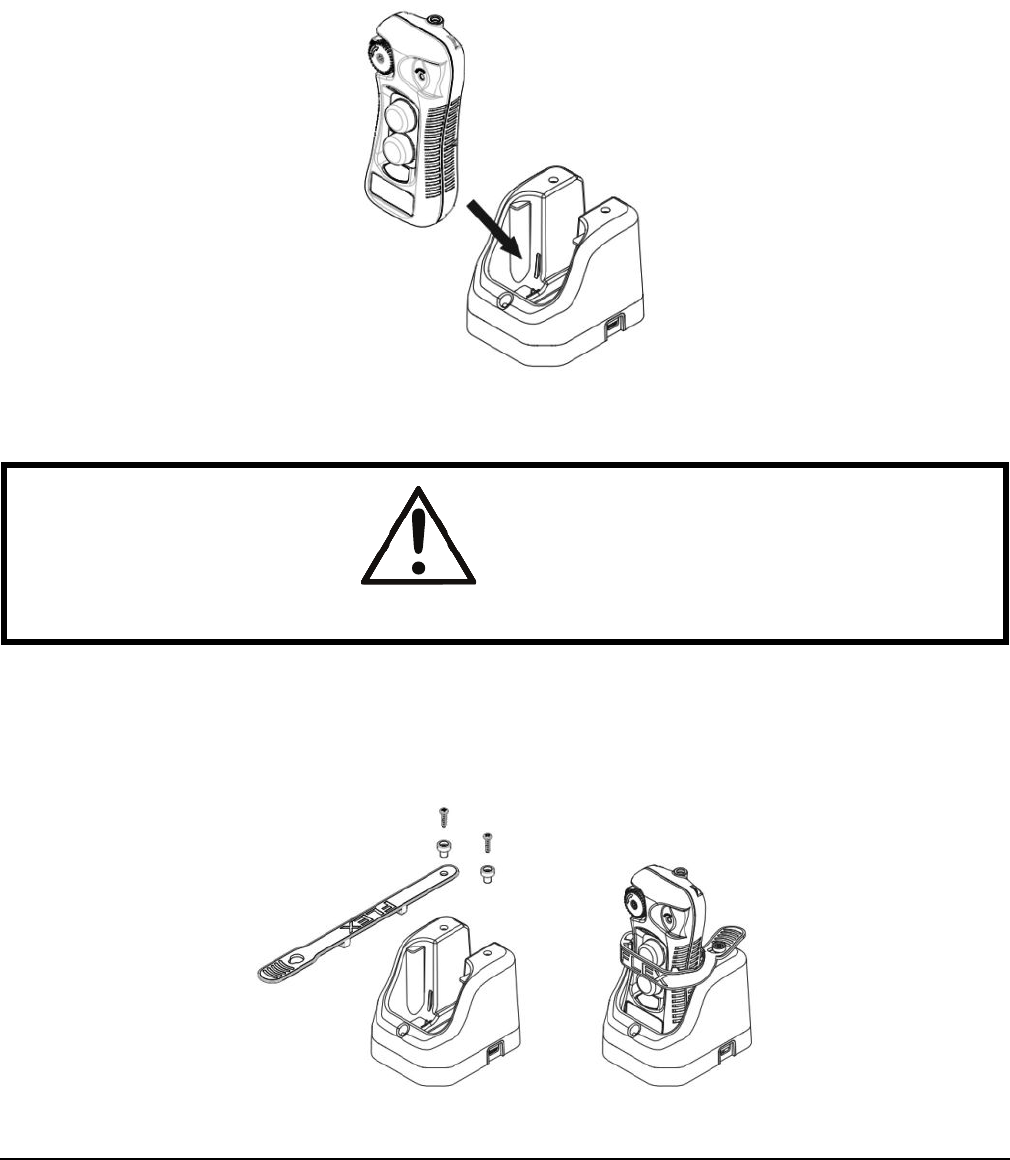
2.9.3 Charging
1. The Flex Duo transmitters are designed to accept any off-the-shelf Ni-MH rechargeable batteries.
2. Depending on the battery capacity the average charging time is approximately 1.5 hours from completely
drained to fully charged.
3. Solid red on the LED represents charging in progress, solid green represents batteries fully charged, and LED
off represents no batteries detected.
Figure 2-4
2.9.4 Retaining Belt
For mobile applications, the retaining belt can be used to prevent the transmitter from becoming loose in the cradle
or falling out when the equipment moves through rough terrain.
Figure 2-5
WARNING
Do not use rechargeable lithium ion batteries as they will damage both the transmitter and the charging station.

Flex Duo Technical Manual
November 2020
Page 15
2.9.5 Wall Mounting the Charger
The Flex Duo charging cradle has two holes located in the back, vertical face of the unit. These holes allow the
cradle to be mounted on a wall by sliding the cradle over the two screws and then sliding down to secure the cradle
onto the screw heads.
Figure 2-6

Flex Duo Technical Manual
November 2020
Page 16
3 General System Information
3.1 General Operation
1. Reset the STOP button located on the top left-hand corner of the transmitter by
rotating it clockwise or counterclockwise; the button will pop up. Transmitter is
powered on when the STOP button is elevated.
2. After turning on the transmitter power, check the Status LED on the transmitter for
any sign of system irregularities. See Section 6.1 on page 41. If the transmitter is
in good working order, the Status LED will display solid green for up to 2 seconds
at power on (no faults detected).
3. Press and hold both PB1 and PB2 at the same time for 1 second to activate the
receiver MAIN relays (Status LED solid green). When the receiver MAIN relays
are activated, the Status LED will change from solid green to solid orange (system
on). Then press any pushbutton on the transmitter to begin operation. Pressing
any pushbutton prior to executing the START command at startup will result in no
signals transmitted (Status LED blinks orange).
NOTE: If the Status LED does not change from green to orange, confirm that the
serial number and channel match between the transmitter and receiver.
4. In case of an emergency, press down the STOP button to disconnect the receiver
MAIN relays and the transmitter power (Status LED blinks 3 reds and then shuts
off). To resume operation after confirming safe conditions are present, rotate the
STOP button clockwise or counterclockwise; the button will pop up. Then press
and hold both PB1 and PB2 pushbuttons at the same time for 1 second to
reconnect the receiver MAIN relays.
5. After 5 minutes of inactivity (pushbutton not pressed) the receiver MAIN relays are
temporarily disconnected. See Section 4.1.5 on page 27. The Status LED blinks
3 reds and then shuts off. Press and hold both PB1 and PB2 to resume operation.
See Section 4.1.6.2 on page 28.
6. Turn off the transmitter power by pressing down the STOP button. It will
disconnect the transmitter power and the receiver MAIN relays altogether (Status
LED blinks 3 reds and then shuts off).
Figure 3-1
PRESS

Flex Duo Technical Manual
November 2020
Page 17
3.2 Transmitter
3.2.1 External Illustration
Figure 3-2
1. STOP Button 5. Ring Hook Attachment Slot
2. Pushbutton 1 (PB1) 6. Battery Cover Screw
3. Pushbutton 2 (PB2) 7. System Information
4. Status LED Indicator 8. Lanyard and Waist Belt Attachment Slot
1
2
3
4
5
6
7
8

Flex Duo Technical Manual
November 2020
Page 18
3.2.2 Internal Illustration
Figure 3-3
1. RF/Encoder Board 5. Pushbutton 2 (PB2)
2. Status LED Indicator 6. STOP Button Contacts
3. Infrared Sensors 7. Function Dipswitch
4. Pushbutton 1 (PB1) 8. Battery Contacts
1
4
5
2
6
7
8
3
Flex Duo Technical Manual
November 2020
Page 19
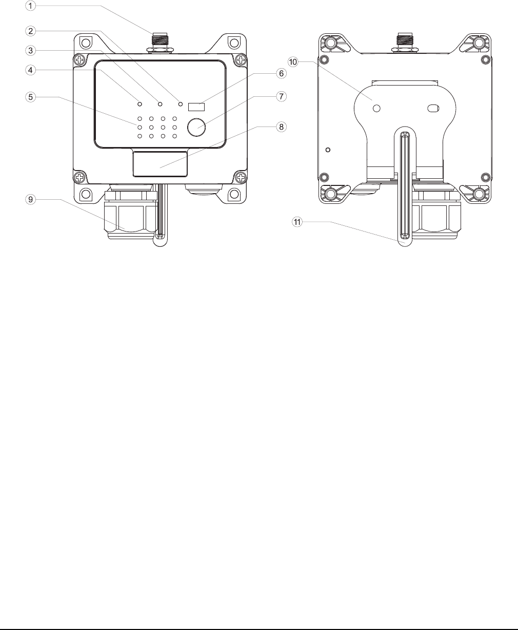
3.3 Receiver
3.3.1 External Illustration
Figure 3-4
1. External Antenna Port 7. Remote Pairing Button
2. COM LED Indicator 8. System Information
3. Status LED Indicator 9. Cord Grip
4. Power LED Indicator 10. Mounting Bracket (Optional)
5. Output Relay LED Indicators 11. Mounting Bracket Release
6. Infrared Sensors

Flex Duo Technical Manual
November 2020
Page 20
3.3.2 Internal Illustration
Figure 3-5
1. RF/Decoder Board 5. Channel Dipswitch
2. Internal Antenna 6. Programming Port
3. INT/EXT Antenna Jumpers 7. Power Transformer
4. Function Dipswitches 8. Relay Board

Flex Duo Technical Manual
November 2020
Page 21
3.3.3 Output Relay Contact Diagrams
Figure 3-6
• The default operation of the Flex Duo system will have the two pushbuttons configured as a pair to perform as
an interlocked motion control with the corresponding output relays setup for momentary contact closure.
• For 9-36VDC power supply, wire #1 corresponds to the negative charge (-), wire #3 corresponds to the positive
charge (+), and wire #2 is for GROUND.
• The circled numbers in the output diagrams above correspond to the wire numbers in the harness.
• Suppressors are recommended on contactor, capacitive loads or inductive loads being driven by Flex relays
due to the possibility of voltage spikes.
Single-speed model
Dual-speed model

Flex Duo Technical Manual
November 2020
Page 22
4 Function Settings
The Flex Duo system comes configured with standard settings out of the box. The following sections describe how
to change or set up additional settings in the system, with the default settings being highlighted in gray.
4.1 Transmitter Settings
4.1.1 Transmitter Firmware Version
This section covers how to check the transmitter firmware version, which is mainly used for troubleshooting
purposes.
4.1.2 Transmitter Channel Settings
In a Flex Duo system, the transmitter channel setting is set to match the receiver it is shipped with. In the case
where a different channel is desired, follow the steps below to change the channel in the transmitter. When
changing the channel of the system the receiver channel will need to be updated to match. See Section 4.2.1 on
page 30 through Section 4.2.3 on page 31 for information on how to change the receiver channel.
NOTE: Both channel and serial number must match for a transmitter and receiver to pair.
1. Press down the STOP button (transmitter power off).
2. Press and hold PB1 and PB2 at the same time.
3. Reset the STOP button by rotating it clockwise or counterclockwise; it will pop up (transmitter power on).
4. Release PB1 and PB2 at the same time. The Status LED displays current channel setting with red and green
blinks. A green blink represents the tens (+10) and a red blink represents the units (+1). For example, 1 green
blink followed by 5 red blinks is channel 15.
5. Change transmitter channel by pressing PB1 to increment the units (+1) and PB2 to increment the tens (+10).
For example, press PB2 two times and then PB1 four times for channel 24 (Status LED blinks 2 greens and 4
reds). Make sure the newly selected channel is shown on the Status LED before proceeding to the next step
below. Skip step 6 if changing receiver channel is not required.
NOTE: When selecting a new channel, make sure each button press does not exceed 3 seconds.
6. Transfer the newly selected channel to the receiver by pressing and holding both PB1 and PB2 at the same
time until the Status LED turns to solid green (transfer complete).
1. Press down the STOP button (transmitter power off).
2. Set dipswitch position #7 to “0” (down) and #8 to “1” (up).
3. Reset the STOP button by rotating it clockwise or counterclockwise; it will
pop up (transmitter power on).
4. The Status LED displays firmware version with red, green and orange
blinks.
5. There are 4 numbers in the firmware sequence (red, green, orange then
green).
6. The first 3 numbers are the firmware version and the 4th number indicate
the system type. Example: 1 red flash, 3 green flashes, 4 orange flashes
and 1 green flash is firmware 1.3.4.1.
7. Exit Firmware Version mode by resetting the dipswitch position #7 and #8
back to “00” (both down) and then press down the STOP button
(transmitter power off).
Figure 4-1
ON D IP

Flex Duo Technical Manual
November 2020
Page 23
7. Press down the STOP button if solid green is not shown on the Status LED after more than 10 seconds
(transfer incomplete); the transmitter will revert to its previous channel setting. Make sure the receiver is
powered on and within the operating distance during the entire process.
8. Exit Channel Setting mode by pressing down the STOP button (transmitter power off).
Important Note:
Step 6 described above is required if you are intending to change the entire system channel (both transmitter and
receiver). If step 6 is skipped the system will no longer work because the transmitter and receiver channels are
now different (new vs. old). In this case you would have to redo step 1~4 and step 6 to transfer the newly selected
transmitter channel to the receiver.
4.1.3 Remote Pairing
The Flex Duo systems come fully set up out of the box. However, if a spare transmitter is to be paired with an
existing receiver, choose one of the pairing methods below to quickly and easily pair a new transmitter. Note that
the remote pairing will change the serial number and channel to match whatever is being paired. In this case, the
serial number on the label will no longer be accurate.
NOTE: Both channel and serial number must match for a transmitter and receiver to pair.
NOTE: The Flex Duo transmitters are not compatible with Flex EX, Flex EM, Flex Mini, or the Flex EX2 receivers.
A. Transmitter-to-Transmitter Pairing:
Figure 4-3
1. Press down the STOP button on both transmitters (transmitter
power off).
2. On both transmitters, set dipswitch position #7 to “0” (down) and #8
to “1” (up).
3. Reset the STOP buttons by rotating them clockwise or
counterclockwise; they will pop up (transmitter power on).
4. The Status LED will display the firmware version with red, green and
orange blinks.
5. On the original transmitter, output pairing data by pressing and
holding PB2 (Status LED off).
6. On the new transmitter, receive pairing data by pressing and holding
PB1 (Status LED blinks green).
Figure 4-2
ON D I P
PB1
PB2
PB1
PB2
→
Output data – original transmitter Receive data – new transmitter
(press and hold PB2) (press and hold PB1)

Flex Duo Technical Manual
November 2020
Page 24
NOTE: During remote pairing make sure the distance between the two transmitters is within 1 meter.
7. When the Status LED on the new transmitter turns to solid green (while the pushbuttons are still being pressed
down on both transmitters), then the pairing is completed.
8. Release PB2 on original transmitter and PB1 on new transmitter.
9. Exit Remote Pairing mode on both transmitters by resetting dipswitch position #7 and #8 back to “00” (both
down).
10. Press down the STOP buttons (transmitter power off).
B. Receiver-to-Transmitter Pairing (Option 1)
With this method, the use of the remote pairing button on the receiver is required. See Section 3.3.1 on page 19
for the location of the pairing button on the receiver.
1. Press down the STOP button on the transmitter (transmitter power off).
2. On the transmitter, set dipswitch position #7 to “1” (up) and #8 to “0” (down).
Figure 4-4
3. Reset the STOP button by rotating it clockwise or counterclockwise; it will pop up (transmitter power on).
4. The Status LED displays firmware version with red, green and orange blinks.
5. In the receiver, dipswitch S2 position #10 is set to “0” (down). This is the factory default setting and only
requires changing if it has been altered from the default setting.
6. The MAIN relays in the receiver must be deactivated (open) for this pairing to work.
7. Output data from the receiver by pressing and holding the PAIRING button on receiver.
8. Receive data in the transmitter by pressing and holding PB1 on the transmitter (Status LED blinks green).
9. When the transmitter Status LED turns to solid green (while the receiver pairing button and transmitter PB1 are
still being pressed down) the pairing is completed.
10. Exit Remote Pairing mode by resetting the transmitter dipswitch position #7 and #8 back to “00” (both down).
11. Press down the STOP button (transmitter power off).
ON D I P

Flex Duo Technical Manual
November 2020
Page 25
Figure 4-5
C. Receiver-to-Transmitter Pairing (Option 2)
With this method, the use of the remote pairing button on the receiver is not required.
Important Note:
This feature makes pairing transmitters to receivers very easy without the need to access the pairing button on the
receiver to complete the pairing. This option should only be used in well-monitored operations to prevent pairing a
transmitting with an unintended receiver, resulting in a potentially unsafe condition.
1. Press down the STOP button on the transmitter (transmitter power
off).
2. On the transmitter, set dipswitch position #7 to “1” (up) and #8 to “0”
(down).
3. Reset the STOP button by rotating it clockwise or counterclockwise;
it will pop up (transmitter power on).
4. The Status LED displays firmware version with red, green and
orange blinks.
5. In the receiver, set S2 dipswitch position #10 to “1” (up). This is not
the factory default setting and will require the switch to be changed.
6. The MAIN relays in the receiver must be deactivated (open) for this
pairing to work.
7. Receive data in the transmitter by pressing and holding PB1 (Status
LED blinks) until the Status LED turns to solid green, then the pairing
is completed.
8. Exit Remote Pairing mode by resetting the transmitter dipswitch
position #7 and #8 back to “00” (both down).
9. Press down the STOP button (transmitter power off).
Figure 4-6
ON DIP
S2 DIP 10
PB1
PB2
→→
S2 dipswitch position 10 set to “0” Output data – receiver Receiving data – transmitter
in the receiver (press and hold the Pairing button) (press and hold PB1)
ON D I P

Flex Duo Technical Manual
November 2020
Page 26
Figure 4-7
Important Note:
Make sure the pairing process is executed with less than 10 meters between the transmitter and the intended
receiver while no other active receivers are nearby. If there are other active receivers in the area with S2 dip 10 set
to “1”, then pairing issues could occur, resulting in the transmitter pairing with an unintended receiver.
D. Transmitter-to-Receiver Pairing:
With this method, the use of the remote pairing button on the receiver is required. See Section 3.3.1 on page 19
for the location of the pairing button on the receiver.
1. Press down the STOP button on the transmitter (transmitter power
off).
2. On the transmitter set dipswitch position #7 to “1” (up) and #8 to “0”
(down).
3. Reset the STOP button by rotating it clockwise or counterclockwise;
it will pop up (transmitter power on).
4. The Status LED displays firmware version with red, green and
orange blinks.
5. Output data by pressing and holding PB2 on the transmitter (Status
LED off).
6. Receive data by pressing and holding the PAIRING button on
receiver.
7. The MAIN relays in the receiver must be deactivated (open) for this
pairing to work.
8. When the transmitter Status LED turns to solid green (while
transmitter PB1 and receiver pairing button are still being pressed
down) the pairing is completed.
9. Exit Remote Pairing mode by resetting the transmitter dipswitch
position #7 and #8 back to “00” (both down) and press down the
STOP button (transmitter power off).
Figure 4-8
PB1
PB2
→
S2 dipswitch position 10 set to “1” Receiving data – transmitter
in the receiver (press and hold PB1)
ON D I P

Flex Duo Technical Manual
November 2020
Page 27
Figure 4-9
4.1.4 Transmitter Output Power Settings
A. FCC/IC Transmitters
The transmitter is set to 1mW by default as that is the maximum allowed due to FCC regulations. If an output
power less of than 1mW is required, please refer to the Flex IR Programmer manual or contact Magnetek field
service.
B. CE Transmitters
The transmitter is set to 2mW for CE compliance. If an output power less than 2mW is required, refer to the Flex IR
Programmer manual or contact Magnetek field service.
4.1.5 Transmitter Inactivity Timer Settings
After 5 minutes (default) of the transmitter pushbuttons not being pressed, the system will enter a sleep mode and
the receiver MAIN relays will be deactivated.
Dipswitch Settings Output Power
1 000xxxxxxx 1mW
Dipswitch Settings Output Power
2 001xxxxxxx 2mW
Dipswitch Settings Time Dipswitch Settings Time
1 xxx000xxxx 1 minute 5 xxx100xxxx 10 minutes
2 xxx001xxxx 20 seconds 6 xxx101xxxx 30 minutes
3 xxx010xxxx 3 minutes 7 xxx110xxxx 60 minutes
4 xxx011xxxx 5 minutes 8 xxx111xxxx
Constant On
(sleep mode
disabled)
PB1
PB2
→
Output data – transmitter Receiving data – receiver
(press and hold PB2) (press and hold the Pairing button)

Flex Duo Technical Manual
November 2020
Page 28
4.1.6 Transmitter Start Function Settings
4.1.6.1 During Initial Transmitter Power On
When transmitter is powered on (Stop button elevated), press both PB1 and PB2 at the same time (default) or
press any pushbutton to activate the receiver (MAIN relays closed).
Figure 4-10
NOTE: When set to Any Pushbutton Activation, the system startup time is 3 seconds after transmitter power on
(Stop button elevated). Pressing any pushbutton for less than 3 seconds will not start the system.
4.1.6.2 During Sleep Mode
When the transmitter enters sleep mode the system is temporarily deactivated (MAIN relays opened). Press both
PB1 and PB2 at the same time (default) or press any pushbutton to wake up the system (MAIN relays closed).
Dipswitch Settings Function
1 xxxxxxxx0x
PB1 + PB2
Activation
2 xxxxxxxx1x
Any Pushbutton
Activation
Dipswitch Settings Function
1 xxxxxxxxx0
PB1 + PB2
Reactivation
2 xxxxxxxxx1
Any Pushbutton
Reactivation
PRESS

Flex Duo Technical Manual
November 2020
Page 29
4.1.7 Infrared Programming
Other custom functions and settings not listed in this manual can be programmed via the Flex IR programmer unit.
Refer to the Flex IR Programmer manual or contact Magnetek field service for more information.
The infrared programmer needs to have firmware V176 or newer to support the Flex Duo.
Figure 4-11
Flex Duo Technical Manual
November 2020
Page 30
4.2 Receiver
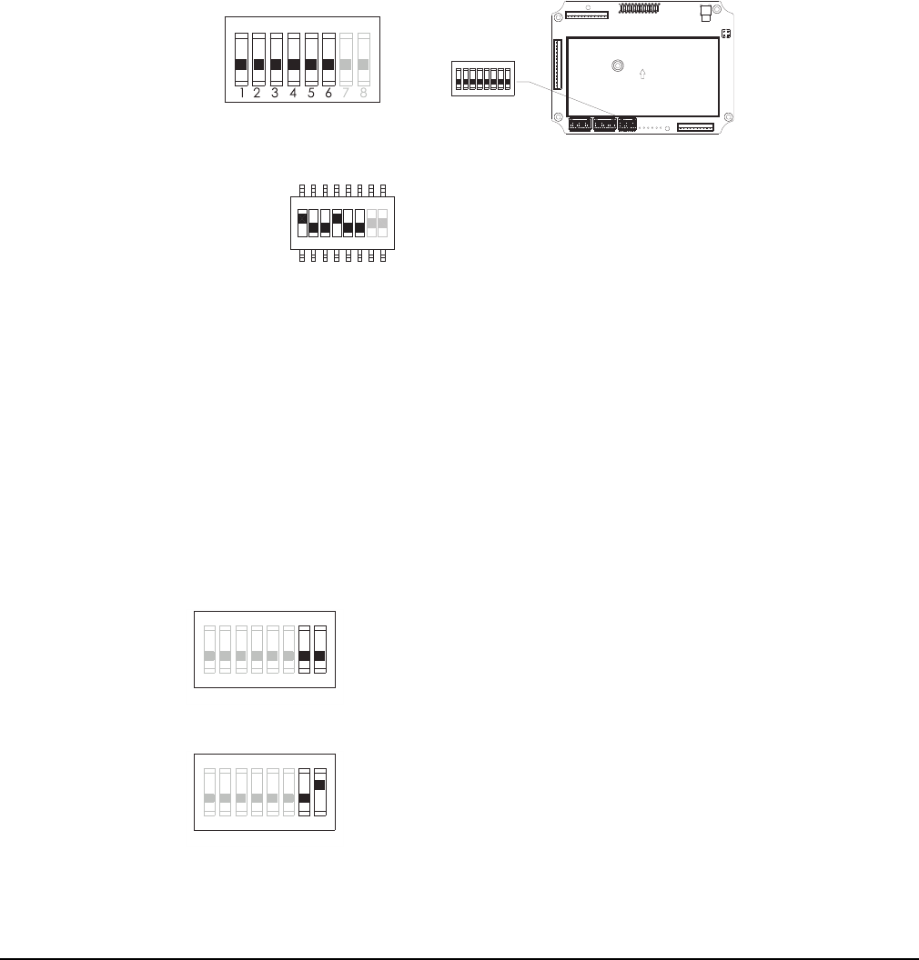
4.2.1 Receiver Channel Settings
Set the receiver channel by configuring the S3 channel dipswitch located on the RF/decoder board. Only the first 6
dip positions are used for channel programming. The system channels table in Section 4.2.3 on page 31
illustrates which dipswitch setting corresponds to which channel. Once the receiver channel is altered, make sure
to change the transmitter channel as well. The channel (and serial number) on both transmitter and receiver must
be identical for the system to communicate. See Section 4.1.2 on page 22 for transmitter channel settings.
NOTE: Transmitter-to-receiver remote pairing (Section 4.1.3 on page 23) will override the channel dipswitch
setting in the receiver.
Figure 4-12
The above dipswitch setting “1 0 0 1 0 0” corresponds to “channel 36” in the system channels table in Section
4.2.3 on page 31.
4.2.2 Receiver Channel Scanning Function
By default, the Flex Duo receiver will not have channel scanning enabled, but rather be set to a single channel.
However, the receiver can be set up to scan multiple channels in cases when it is needed for one transmitter to
lock out the other transmitter during operation. To do this, set the second transmitter channel to be one higher than
the first transmitter channel (Section 4.1.2 on page 22), then see below on how to set the channel scanning
function to scan 2 channels.
NOTE: Once one transmitter takes control of the receiver, the other transmitters will be locked out until the active
transmitter is powered off or inactivity timer is reached.
Example: If the first 6 dipswitch positions are set to channel 01 (000001), when set to 2-channel scanning (type-2
above) the receiver will only scan channel 01 and 02.
71 423 56
8
1 2 3 4 5 6 7 8
ON D I P
ON DIP
S3 DIP 1~6
Example:
Top position → “1”
Bottom position → “0”
1 2 3 4 5 6 7 8
ON DIP
S3 DIP 7~8
1 2 3 4 5 6 7 8
ON DIP
S3 DIP 7~8
(1) → “00” manufacture preset (channel X)
(2) → “01” scans 2 channels (channel X and channel X+1)
* Channel X → channel set on the Channel dipswitch.

Flex Duo Technical Manual
November 2020
Page 31
4.2.3 System Channels Table
Channel
Receiver Dipswitch
Setting
Frequency Channel
Receiver Dipswitch
Setting
Frequency
01 000001 433.050MHz 32 100000 433.825MHz
02 000010 433.075MHz 33 100001 433.850MHz
03 000011 433.100MHz 34 100010 433.875MHz
04 000100 433.125MHz 35 100011 433.900MHz
05 000101 433.150MHz 36 100100 433.925MHz
06 000110 433.175MHz 37 100101 433.950MHz
07 000111 433.200MHz 38 100110 433.975MHz
08 001000 433.225MHz 39 100111 434.000MHz
09 001001 433.250MHz 40 101000 434.025MHz
10 001010 433.275MHz 41 101001 434.050MHz
11 001011 433.300MHz 42 101010 434.075MHz
12 001100 433.325MHz 43 101011 434.100MHz
13 001101 433.350MHz 44 101100 434.125MHz
14 001110 433.375MHz 45 101101 434.150MHz
15 001111 433.400MHz 46 101110 434.175MHz
16 010000 433.425MHz 47 101111 434.200MHz
17 010001 433.450MHz 48 110000 434.225MHz
18 010010 433.475MHz 49 110001 434.250MHz
19 010011 433.500MHz 50 110010 434.275MHz
20 010100 433.525MHz 51 110011 434.300MHz
21 010101 433.550MHz 52 110100 434.325MHz
22 010110 433.575MHz 53 110101 434.350MHz
23 010111 433.600MHz 54 110110 434.375MHz
24 011000 433.625MHz
55 110111 434.400MHz
25 011001 433.650MHz 56 111000 434.425MHz
26 011010 433.675MHz 57 111001 434.450MHz
27 011011 433.700MHz 58 111010 434.475MHz
28 011100 433.725MHz 59 111011 434.500MHz
29 011101 433.750MHz 60 111100 434.525MHz
30 011110 433.775MHz 61 111101 434.550MHz
31 011111 433.800MHz 62 111110 434.575MHz

Flex Duo Technical Manual
November 2020
Page 32
4.2.4 Output Relay Configurations
4.2.4.1 Output Relay Types
The output relay functions described below and on the next page pertain to the settings discussed in Section
4.2.5.1 on page 34 as well as Section 4.2.5.2 on page 35.
1. 2 output relays per motion - single-speed systems only
Output relays with Forward (F) and Reverse (R) 1st speed only.
2. 3 output relays per motion with shared 2nd-speed output relay
Output relays with Forward 1st speed (F1), Reverse 1st speed (R1) and Forward/Reverse 2nd speed (F/R2).
Forward and Reverse 2nd speed (F/R2) share the same output relay.
4.2.4.2 Output Relay Actions at 2nd Speed
1. 3 output relays configuration with Closed/Closed contact at 2nd speed
F1 (or R1) output relay closed at 1st speed and F1 + F/R2 (or R1 + F/R2) output relays closed at 2nd speed.
See Table 4.2.5.1 on page 34 on how to set to this function.
4.2.4.3 ON/OFF Pushbutton Function
The user can set any of the two pushbuttons on the transmitter to behave like a
mechanical ON and OFF rocker or toggle switch. The ON output relay closes when ON
pushbutton is pressed (OFF output relay opens) and OFF output relay closes when OFF
pushbutton is pressed (ON output relay opens). See Table 4.2.5.1 on page 34 on how to
set to this function.
F1
F/R2
R1 R1F1
F/R2
Forward 1
st
speed pushbutton pressed Forward 2
nd
speed pushbutton pressed
↓↓
PB1
PB2

Flex Duo Technical Manual
November 2020
Page 33
4.2.4.4 Brake Function (dual-speed systems only)
When the transmitter pushbutton is released from 2nd speed up to 1st speed, both 1st and 2nd speed output
relays will open for up to 1 second and then with 1st speed output relay closed thereafter. See Section 4.2.5.1 on
page 34 for how to set to this function.
4.2.4.5 External Warning Device
The user can install an external warning device (rotating lights, horn, etc.) to the K10 Function output relay of the
receiver. There are several settings for how this relay operates and are shown in Section 4.2.7 on page 36.
4.2.4.6 Momentary Contact
When pushbutton is released, the corresponding output relay will open or deactivate. This type of relay action
usually applies to external applications such as a horn or buzzer. See Section 4.2.5.2 on page 35 on how to set to
this function.
4.2.4.7 Toggled Contact
When pushbutton is released, the corresponding output relay will remain closed until next time the user presses
the same pushbutton again which will open the relay contacts. This type of relay action usually applies to external
application such as lights. See Section 4.2.5.2 on page 35 for the settings that operate this relay.

Flex Duo Technical Manual
November 2020
Page 34
4.2.5 Dipswitch Settings
4.2.5.1 Interlocked Pushbutton Pair
Interlocked means that when both buttons are pressed at the same time no relay outputs will be commanded.
Pressing both buttons simultaneously will cancel each other out. Interlocked setting usually applies to electric
motor's forward and reverse motion and On and Off switches.
Figure 4-13
NOTE: Five dip positions correspond to a pushbutton pair.
* External warning function requires installing an external warning device to the K10 Function output relay.
Dip Settings Function
00000 Single-speed only (default setting for Single Speed Systems)
00001
3 output relays Closed/Closed relay action at 2nd speed
(default setting for Two-Speed Systems)
00010 On (PB1) & Off (PB2)
00100
On (PB1) & Off (PB2) with EMS
(EMS → all relays deactivate when STOP button is pressed)
00110 FWD (PB1) / REV (PB2) toggled
00111
FWD (PB1) / REV (PB2) toggled
(EMS → all relays deactivate when STOP button is pressed)
01000 Single speed + External warning*
01001 3 output relays Closed/Closed relay action + External warning*
01010 3 output relays Closed/Closed relay action + Brake
01011 3 output relays Closed/Closed relay action + Brake + External warning*
ON DI P
PB1 2
~
S1 DIP 1~5
ON DIP

Flex Duo Technical Manual
November 2020
Page 35
4.2.5.2 Non-Interlocked Pushbutton Pair
Non-interlocked means that when both buttons are pressed at the same the time, the receiver will respond to each
button press by commanding relays as configured. Pressing both buttons at the same will not cancel each other
out. It usually applies to equipment's auxiliary functions such as lights, horn, or buzzer.
Figure 4-14
NOTE: Five dip positions correspond to a pushbutton pair.
* EMS → all relays deactivate when STOP button is pressed
Dip Settings Bottom Pushbutton (PB2) Top Pushbutton (PB1)
10000 Momentary Momentary
10001 Momentary Toggle
10010 Momentary Toggle (EMS)
10100 Toggle Momentary
10101 Toggle Toggle
10110 Toggle Toggle (EMS)
11000 Toggle (EMS) Momentary
11001 Toggle (EMS) Toggle
11010 Toggle (EMS) Toggle (EMS)
ON DI P
PB1 2
~
S1 DIP 1~5
ON DIP

Flex Duo Technical Manual
November 2020
Page 36
4.2.6 Other Dipswitch Settings
Figure 4-15
4.2.7 Other Function Output Relay Settings
Listed below are other types of functions that can be outputted through the K10 Function output via the Flex IR
programmer unit. Refer to the Flex IR programmer manual or contact Magnetek field service for more details. EXT
is the default setting.
S2 Dip Position 8 Function
Dip set to “1” or up
Display system firmware version
- There are 4 numbers in the firmware sequence
(red, green, orange then green)
- The first 3 numbers are the firmware version and the
4th number indicate the system type.
Example: 1 red flash, 3 green flashes, 4 orange
flashes and 1 green flash is firmware 1.3.4.1.
S2 Dip Position 9 Function
Dip set to “1” or up System testing (receiver MAIN relays disabled)
S2 Dip Position 10 Function
Dip set to “0” or down
Receiver-to-transmitter remote pairing
(pressing the Pairing button required)
Dip set to 1” or up
Receiver-to-transmitter remote pairing
(pressing the Pairing button not required)
EXT:
Function relay closes when START command is initiated and opens when the START
commands stops.
LV: Function relay closes when receiver voltage is low.
ID: Function relay works simultaneously with all motion commands.
S/P:
Function relay closes when START command is initiated and opens only when transmitter
power is turned off.
HORN:
Function relay closes for up to 3 seconds when START command is initiated during
transmitter startup.
RESET:
Function relay closes when START command is initiated and opens when let go. Works
during initial transmitter startup and inactivity timer START reset.
ON D IP
S2 DIP 8~10
ON DIP

Flex Duo Technical Manual
November 2020
Page 37
4.2.8 Warning Device Installation
The warning device can be easily fitted onto the receiver enclosure. The K10 relay output to the warning device
can be configured to operate in several manners as described in Section 4.2.4.5 on page 33 and Section 4.2.7
on page 36. The warning device is connected to the CN5 port located inside the receiver.
Figure 4-16

Flex Duo Technical Manual
November 2020
Page 38
5 Receiver Installation
5.1 Pre-installation Precautions
1. Make sure the transmitter and receiver are with identical serial number and channel.
2. Make sure the receiver is not set to the same channel as any other systems in use in the surrounding area.
Having each system set to a different channel than other receivers in the area prevents systems from
interfering with each other.
3. Make sure the hoist or equipment is working properly prior to installation.
4. Make sure the power source to the receiver matches the receiver's settings.
5. Switch off the main power source to the hoist or equipment prior to installation.
5.2 Receiver Mounting
Figure 5-1
4
.
60
"
4.66"
11
7
mm
118 mm
141 mm
5.56"
55 mm
2.17"
19 mm
0.74"
4.60"
4.66"
117 mm
118 mm
1
4
1 mm
5.56"
55 mm
2.17"
With Optional Removable Mounting Bracket

Flex Duo Technical Manual
November 2020
Page 39
5. For better reception, make sure the receiver is in an upright position.
6. Drill four holes if mounting straight onto the panel or two holes if using the optional mounting bracket.
7. Make sure the screws are tightened after installation.
Figure 5-3
8. If using the mounting bracket, slide the receiver down along the guided track to secure the receiver to the
mounting bracket. Make sure to leave enough slack in the pigtail to accommodate sliding the receiver back off
the bracket in case service is ever needed in the future.
9. Remove the receiver by pressing down the bracket release and pull the receiver upward until it clears the
guided track.
1. For best reception, the location of the receiver should be visible to
the transmitter at all times with a clear line of sight.
2. The location selected should not be exposed to high levels of
electric noise. Mounting the receiver next to an unshielded variable
frequency drive or an electromagnetic interference / radio-frequency
interference (EMI / RFI) generator may cause radio interference.
Always locate the receiver as far away from variable frequency
drives, electric motors, and EMI / RFI generators as possible.
3. Ensure the selected location has adequate space to accommodate
the receiver and pigtail. If an external antenna is required, always
locate the receiver where the antenna is free from any obstacles to
avoid the possibility of antenna damage.
4. The Flex Duo receiver will be set to internal antenna by default.
When installing an external antenna, make sure the MCX antenna
jack located on the RF/decoder board inside the receiver is
connected and the jumper is set to the “EXT” position.
Figure 5-2
300 mm
Control
Panel
1
0
4
m
m
O.
56mm
1
0
2
m
m
3
9m
m
Ø4 8mm
.
No Mounting Bracket Optional Mounting Bracket

Flex Duo Technical Manual
November 2020
Page 40
Figure 5-4
Install Remove

Flex Duo Technical Manual
November 2020
Page 41
6 System Status Light Indications
6.1 Transmitter Status Indications
Type Display Type Indication
1 Solid red Voltage below 1.8V at initial power on or during operation
2 (FCC)
Solid red → 3 red blinks
→ off
Voltage below 1.75V during operation
(receiver MAIN relays shut off)
2 (CE) Solid red → off
Voltage below 1.75V during operation
(receiver MAIN relays shut off)
3
1 red blink followed by
a 2-second pause
Voltage below 1.85V during operation
(change batteries suggested)
4A
2 red blinks followed by
a 2-second pause
Defective or jammed pushbutton detected
at initial power on
4B No light displayed
When defective pushbutton condition occurs (2 red blinks,
type 4A above), find out which pushbutton is defective by
pressing all of them one at a time. If the pushbutton is in good
working order when pressed, the Status LED is off.
If the Status LED maintained 2 red blinks then the
pushbutton is defective.
5
4 red blinks followed by
a 2-second pause
Transmitter is unable to lock onto the assigned channel
6
Solid green for up to
2 seconds
Transmitter power on with no faults detected
7 Blinking green Transmission in progress
8 Blinking orange
Pressing any pushbutton prior to executing
the START command at power on
9 (FCC) 3 slow red blinks → off STOP button pressed down
10
2 orange blinks followed by
a 2-second pause
Receiver MAIN relays jammed or defective
11
3 orange blinks followed by
a 2-second pause
Decoding processors defective
12
Solid orange when the
START button is pressed and
hold at initial system startup
Receiver MAIN relays activated

Flex Duo Technical Manual
November 2020
Page 42
6.2 Receiver Status Indications
6.3 Receiver Power Indications
6.4 Receiver COM Indications
Type Display Type (Green & Red) Indication
1 Fast green blinks Decoding in process
2 Slow green blinks Decoding on standby
3 2 red blinks Receiver MAIN relays jammed or defective
4 3 red blinks Decoding processors defective
5 4 red blinks Receiving RF defective
6 Fast red blinks Incorrect transmitter serial number
7 Solid red Receiver low voltage
8 No light displayed Decoding processors defective
9
3 slow red blinks followed by
slow green blinks
STOP button pressed down
Type Display Type (Red) Indication
1 On Power to receiver
2 Off No power to receiver
Type Display Type (Red) Indication
1 On Power to relay board
2 Off No power to relay board

Flex Duo Technical Manual
November 2020
Page 43
7 General Specifications
Frequency Range: 433.050MHz - 434.575MHz
Number of Channels: 62 channels
Channel Spacing: 25KHz
Modulation: Digital Frequency Modulation based on Manchester Code, 20-bit
address, 32-bit CRC and Hamming Code
Encoder & Decoder: Microprocessor-controlled
Transmitting Range: >100 meters (300 feet)
Hamming Distance: >6
Frequency Control: Synthesized PLL
Receiver Type: Frequency Auto Scanning
Receiver Sensitivity: -116 dBm
Spurious Emission: -50 dB
Antenna Impedance: 50 ohms
Responding Time: 40 mS (average)
Transmitting Power: 1.0 mW
Enclosure Type: NEMA4
Enclosure Rating: IP66
Output Contact Rating: 250VAC/28VDC @ 6 Amps
Transmitter Operating Voltage: 3.0VDC
Receiver Power Consumption: 7VA (max)
Available Receiver Voltages: 9 - 36VDC
24 - 48VAC
48 - 240VAC
Operating Temperature: -25°C - 75°C / -13°F - 167°F
Transmitter Dimension: 130 mm (L) x 55 mm (W) x 40 mm (H)
5.12 in. (L) x 2.17 in. (W) x 1.57 in. (H)
Receiver Dimension: 120 mm (L) x 90 mm (W) x 55 mm (H)
4.72 in. (L) x 3.54 in. (W) x 2.17 in. (H)
Transmitter Weight: 183 g / 6.4 oz (including batteries)
Receiver Weight: 900 g / 2.0 lb (including output cable)

Flex Duo Technical Manual
November 2020
Page 44
7.1 Part Number Guide
FCC / IC Specific Numbers
FLEX-DUO-MRX-RX-101 Flex Duo-MRX receiver w/ 24-48 VAC Power Supply
FLEX-DUO-MRX-RX-101-CSA Flex Duo-MRX receiver w/ 24-48 VAC Power Supply - CSA marked
FLEX-DUO-MRX-RX-102 Flex Duo-MRX receiver w/ 48-240 VAC Power Supply
FLEX-DUO-MRX-RX-102-CSA Flex Duo-MRX receiver w/ 48-240 VAC Power Supply - CSA marked
FLEX-DUO-MRX-RX-103 Flex Duo-MRX receiver w/ 9-36 VDC Power Supply
FLEX-DUO-MRX-RX-103-CSA Flex Duo-MRX receiver w/ 9-36 VDC Power Supply - CSA marked
FLEX-DUO-TX-1S Flex Duo transmitter, Single speed buttons
FLEX-DUO-TX-2S Flex Duo transmitter, Two speed buttons
CE Specific Numbers
FLEX-DUO-MRX-RX-101-CE Flex Duo-MRX receiver w/ 24-48 VAC Power Supply
FLEX-DUO-MRX-RX-102-CE Flex Duo-MRX receiver w/ 48-240 VAC Power Supply
FLEX-DUO-MRX-RX-103-CE Flex Duo-MRX receiver w/ 9-36 VDC Power Supply
FLEX-DUO-TX-1S-CE Flex Duo transmitter, Single speed buttons
FLEX-DUO-TX-2S-CE Flex Duo transmitter, Two speed buttons
General Numbers
FLEX-DUO-CHARGER Flex Duo charging cradle w/o USB cable or power supply
FLEX-DUO-CHARGER-AC Flex Duo charging cradle w USB cable and 110VAC power supply
(U.S. style plug)
FLEX-DUO-TX-BOOT Molded rubber guard for Flex Duo transmitter
FLEX-DUO-TX-POUCH Vinyl pouch for Flex Duo transmitter
FLEX-DUO-WRISTWRAP Wrist strap
FLEX-DUO-TX-DECAL Flex Duo transmitter label set

EU Declaration of Conformity Certificate
For the following equipment:
Product : Flex Series Radio Remote Control System
Multiple Listee Model No. : Flex Duo, Flex Base, Flex EX2, Flex Wave
Manufacturer’s Name : Magnetek, Inc.
Manufacturer’s Address : N49W13650 Campbell Drive
Menomonee Falls, WI 53051
The undersigned hereby declares on behalf of Magnetek, that the above-referenced product, to which this declaration relates, is in
conformity with the provisions of the following directives:
• CE Mark Directive (93/68/EEC)
• Machinery Safety Directive (2006/42/EC)
• Radio Equipment Directive (2014/53/EU)
• EMC Directive (2014/30/EU)
• ROHS2 Directive (2011/65/EU)
• General Product Safety (2001/95/EC)
The standards relevant for the evaluation of the product referenced above conformity to the directive requirements are as follows:
EN 301 489-1 V2.2.1
EN 301 489-3 V2.2.1
EN 300 220-1 V2.4.1
EN 300 220-2 V2.4.1
EN 60950:2006+A1+A11+A12
EN 60204-32:2008
EN ISO 13849-1:2015 (PLd)
EN 13557:2003+A2:2008
EN 60529 (IP66)
EN 62479
EN 55032
EN 55024
The Technical Construction File is maintained at: Columbus McKinnon Corporation
13830 Ballantyne Corporate Place
Suite 300
Charlotte, NC 28277 USA
The European contact for technical documentation is: Ian Knight
STAHL CraneSystems, Ltd.
Unit 2 Forge Mills Park
Station Road
Coleshill
Warwickshire B46 1JH
United Kingdom
Per Annex II.B of the Machinery Directive (2006/42/EC):
The machinery, product, assembly or sub-assembly covered by this Declaration of Conformity must not be put into service until
the machinery into which it is to be incorporated has been declared in conformity with the provisions of the applicable
Directive(s). This statement is only necessary where the product is to be incorporated into a machine or system (e.g. a safety
component).
Signature of Authorized Person:
Benjamin J. Stoller
Global Product Manager - Controls
Columbus McKinnon Corporation
Date of Issuance: 10 August 2020
EU Declaration of Conformity Flex Series English

Flex Duo System
Radio Control Equipment Technical Manual
November 2020
