
INSTRUCTION MANUAL
PLEASE READ THIS INSTRUCTION MANUAL
BEFORE YOU BEGIN ASSEMBLY
!
AIR UNLIMITED
MODEL # 402008
AIR UNLIMITED
cascadehealthandtness.com
HEALTH & FITNESS
R
INTERVALREADOUTS
H.R.
target
HR
interval
20-10
interval
20-30
interval
custom
target
time
target
distance
target
calories
INTERVAL
20/10
20/30
CUSTOM
TOTAL TIME
REST
TARGET
TIME
DISTANCE
CALORIES
TARGET HR
65%
OF
80%
OF
M
AX
HR
BPM
NO HR SIGNAL
TARGE T HR ACHIEVED
SPEED UP
SLOW DOWN
GO
TIME?
DISTANCE?
AVERAGE
TOTAL
AVEMAX
WATT S
RPM / AGE?
CALORIES?
TOTAL
AVEMAX
SPEED
KPH
MPH
KM
MILE
HEART RATE
READY
REMAINING
ELAPSED
stop
enter
start

2
cascadehealthandtness.com
contents
safety information 03
customer support 04
assembly instructions 05
Air Bike Unlimited features explained 12
computer instructions 14
- quick start
- button functions
- console display and feedback
- using workout programs
how to take care of your Air Bike Unlimited 19
troubleshooting 20
exercising with your Air Bike Unlimited 20
exploded diagrams and parts list 22
I-1 Console Assembly 24
your warranty 25

Safety Information
3
cascadehealthandtness.com
HEALTH & FITNESS
R
PLEASE READ THIS INSTRUCTION MANUAL BEFORE YOU BEGIN ASSEMBLY. GREAT
CARE HAS BEEN TAKEN TO DESIGN THESE INSTRUCTIONS AND FOLLOWING THEM
WILL HELP YOU WITH QUICKER ASSEMBLY AND MINIMISE THE RISK OF INJURY
YOU ARE RESPONSIBLE FOR YOUR OWN SAFETY -
THIS LIST IS NOT EXHAUSTIVE.
•
Always assemble and operate the product on a level surface,
ensure that the product is stable before use.
• Trytoensurethatyourbackisstraightwhilstexercising,
especially for long periods
•
The safety level of this equipment can only be maintained
if it is regularly examined for wear and tear
•
Keep hands away from moving parts.
•
Replace defective components immediately, and/or
keep the equipment out of use until it is repaired.
•
Use only the adjustment settings as described in the
instructions. Always use the correct adjustment pin/xing.
•
Special attention should be taken to inspect the
components, such as pulleys, bearings, straps, rollers are
always more susceptible to wear before use.
•
Never leave any adjustment devices projecting from the
product.
•
Always wear suitable clothing and footwear e.g. tracksuit /
shorts / training shoes
•
Remove all personal jewellery before exercising.
•
Ensure you warm-up well before using the equipment as
this will help to prevent muscle strain.
•
After eating, allow 1-2 hours before exercising as this will
help to prevent muscle strain.
• Neveroverloadtheequipment–themaximumuserweight
of this rower is 150kg.
•
Don’t rock the rower form side to side
•
Never use the equipment in any other manner other than
the ways explained in these instructions and/or any
wall-chart supplied.
•
This product has an intergrated resistance system without
a constant power mode that is governed by magnetic
resistance.
•
Losing grip or suddenly releasing the handle could result in
an uncontrolled return, ensure there is freee space around
the product.
•
You may want to store this product away to save space -
be aware of moving mechanical parts which could cause
injury.
•
To prevent shock, keep all electical components, shuch as
the console, motor, cord and switch away from water.
•
Do not use any accessories that aren’t specically
recommended by the manufacturer, these might cause
injuries or cause the unit to fail.
•
Work within your recommended exercise level, do NOT
work to exhaustion.
•
If you feel any pain or abnormal symptoms, STOP YOUR
WORKOUT IMMEDIATELY. Consult your physician
immediately.
•
Parents and others in charge of children should be aware
of their responsibility, because the natural play instinct
and the fondness of experimenting of children can lead to
situations and behaviour for which the training equipment
is not intended
•
If children are allowed to use the equipment,
their mental and physical development and above all
their temperament should be taken into account. They
should be controlled and instructed in the correct use
of the equipment.
•
The equipment is under no circumstances
suitable as a children’s toy.
•
This appliance is not intended for use by persons
(including children) with reduced physical, sensory or
mental capabilities, or lack of experience and knowledge,
unless they have been given supervision or instruction
concerning use of the appliance by a person responsible
for their safety.
• The free area shall be not less than 0.6 m greater than
the training area in the directions from which the
equipment is accessed.
Safety Standards
This rower meets the requirements of the EN ISO 20957-1: 2013, EN ISO 20957-5: 2016 Class SC
and also the EU’s EMC and Low Voltage directives (where applicable).
It is important that you keep these instructions for future reference.
!
This product is not suitable for therapeutic purposes.
Injuries to health may result from incorrect or excessive training.
!
Heart Rate Monitoring System may be inaccurate, Over exercise may result in
serious injury or death. If you feel faint stop exercising immediately !
Be aware of the edges on the rower track rail when in use or move it around.
!
!

Customer Support
Should you require any assistance regarding this product please gather the following information,
and then contact us using the details below:
1. Serial no. - this can be found on
the sticker below, located as indicated.
For future reference, please write down
your serial number in the space
provided below.
2. Original purchase date
3. Place of purchase
4. Information about the place
and conditions of use
5. Precise description of the issue/defect
Your Serial No. is:
Contact Us
4
cascadehealthandtness.com
info@cascadehealthandfitness.com
p 425-402-4062
info@cascadehealthandfitness.com
p 425-402-4062
Care & Maintenance
•
Always place the equipment in a dry environment.
•
Use a warm, damp cloth to keep the product clean.
•
No wet cleaning of electrical components, unplug before any care and maintenance
•
The safety level of the equipment can be maintained only if it is regularly examined for damage and wear. This
includes any ropes, pulleys, nuts, bolts, moving parts, bushes, chains, wheels, bearings & connection points etc
•
Ensure that you inspect the product regularly - at least once a week is recommended.
•
Ensure that all xings are tight before use.
•
Always replace damaged / worn components with original parts from the manufacturer.
Protect the environment by not disposing of this product with household waste.
Check your local authority for recycling advice and facilities (Europe only).

Assembly Instruction
If you suspect you may have some parts missing, please contact
us before going back to your retailer. Refer to the Customer
Support section on page 4 for contact details.
!!
Before you start
1. Prepare your work area -
it is important you assemble
the product in a clean and
uncluttered space.
2. Work with a friend -
we recommend you have
someone assist you with
the assembly as some of the
components are quite heavy.
3. Open the carton -
checking any warnings on
the carton and make sure you
have it the right way up.
4. Unpack the carton
Make sure you have
the following parts:
Console x 1
Console Support
Frame x 1
Parts Tools
Wrench
(13/17)
Part
No.
J4
Part
No.
J5
Part
No.
B
Part
No.
H1
Part
No.
F
x 2
x 2
Pedal set
x 1pair
Front stabilizer
x 1
Part
No.
C
Rear stabilizer
x 1
Disc
Spring
Spacer
Part
No.
E
M8 Nylon
Locknut
Part
No.
I
Main Frame
Part
No.
A
Part
No.
D1
Left Handlebar
x 1
Part
No.
D2
Right Handlebar
x 1
Fix Plate
x 2
Part
No.
G
Foot Peg
x 2
Part
No.
H2
Part
No.
J2
x 4
M8 x 30mm
Screw
M6 x 15mm
Screw
x 6
Part
No.
J6
M10 x 20mm
Allen Head
Bolt
x 8
Wrench
Phillips
Screwdriver
Part
No.
J3
5
Part
No.
J1
End Cap
x 2
Allen Key (6, 5, 4mm)
cascadehealthandtness.com
INTERVAL
READOUTS
H.R.
target
HR
interval
20-10
interval
20-30
interval
custom
target
time
target
distance
target
calories
INTE
RVAL
20/10
20/30
CUSTOM
TOTAL TIME
REST
TARGET
TIME
DISTANCE
CALORIES
TARG
E
T
H
R
65%
OF
80%
OF
M
A
X
HR
BPM
NO HR SIGNA
L
TARGET HR
ACHIEVED
S
P
E
E
D
U
P
S
LO
W
D
O
W
N
GO
TIME?
DISTANCE?
AVERAGE
TOTAL
AVEMAX
WATTS
RPM / AGE?
CALORIES
?
TOT
AL
AVEMAX
SPEED
KPH
MPH
KM
MILE
HEART RATE
READY
REMAINING
ELAPSED
stop
enter
start
HEALTH & FITNESS
R
This cycle takes up
a oor space of 126cm x 70.5cm
and weighs 69.2kg
Bottle
Holder x 1
Part
No.
E2
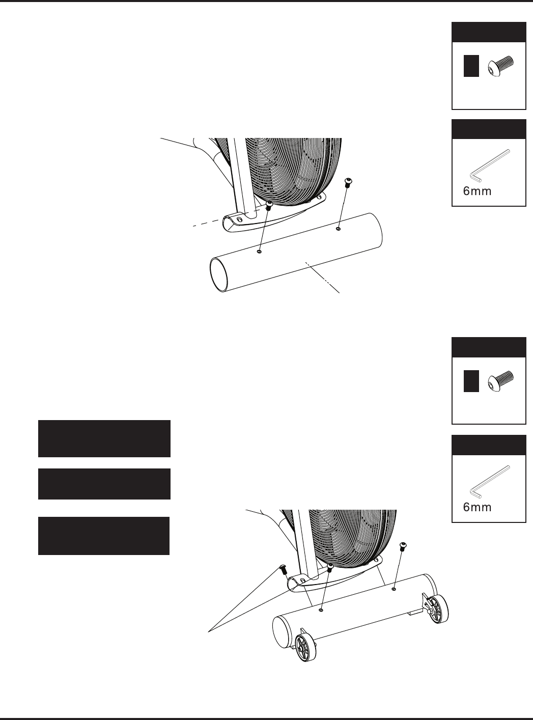
1. Attach the Front Stabilizer
1-1. Remove the cardboard tube from the front end stabilizer bracket
Loosen the two • M10 x 20mm Allen Head Bolt (J6) from the
cardboard tube and remove the cardboard tube.
The cardboard tube is used for packaging protection purposes, which won’t be •
used again during the assembly.
FIXINGS:PARTS:
x 2
Part
No.
J6
Be sure to t the parts in the
same order as the diagrams
shown.
!
Make sure the bolts are fully
tightened with the allen key.
!
Make sure the moving wheels
on the front stabilizer face out
after assembly.
!
FIXINGS:PARTS:
x 4
Part
No.
J6
1-2. Attach the Front Stabilizer
Attach the • Front Stabilizer (B) to the Main Frame (A) with four
M10 x 20mm Allen Head Bolt (J6) and tighten these bolts with
the 6mm Allen Key.
FIXINGS:TOOLS:
FIXINGS:TOOLS:
6
cascadehealthandtness.com
J6
Cardboard Tube
J6

FIXINGS:PARTS:
x 2
Part
No.
J6
Be sure to t the parts in the
same order as the diagrams
shown.
!
Make sure the bolts are fully
tightened with the allen key.
!
FIXINGS:PARTS:
x 4
Part
No.
J6
2. Attach the Rear Stabilizer
2-1. Remove the cardboard tube from the rear end stabilizer bracket
Loosen the two • M10 x 20mm Allen Head Bolt (J6) from the cardboard tube and
remove the cardboard tube.
The cardboard tube is used for packaging protection purposes, which won’t be •
used again during the assembly.
2-2. Attach the Rear Stabilizer
Attach the • Rear Stabilizer (C) to the Main Frame (A) with four
M10 x 20mm Allen Head Bolt (J6) and tighten these bolts with
the 6mm Allen Key..
FIXINGS:TOOLS:
FIXINGS:TOOLS:
7
cascadehealthandtness.com
HEALTH & FITNESS
R
J6
Cardboard Tube
J6

3. Attach the Dual Action Handlebars
Be sure to t the parts in the
same order as the diagrams
shown.
!
Make sure the screws are fully
tightened with the allen key.
!
FIXINGS:PARTS:
x 1
Part
No.
J2
Be sure to t the parts in the
same order as the diagrams
shown.
!
Make sure the foot peg is fully
tightened with the allen key.
!
x 1
Part
No.
J4
x
1
Part
No.
J3
x
3
Part
No.
J5
3-1. Attach the Left Dual Action Handlebar
Slide the • left Dual Action Handlebar (D1) onto the
pivot axle carefully.
Install the • Foot Peg (G) by screwing it on, and tighten
it with the wrench as shown.
Attach the • End Cap (J1) onto the Foot Peg (G)
securely.
3-2. Install the Fix Plate & Linkage Bar
Connect the • left Dual Action Handlebar (D1) and Linkage Bar
with Fix Plate (I), Disc Space r (J4), M8x30mm Screw (J2) and
M8 Nylon Locknut (J3) and tighten with 5mm Allen Key & 13/17
Wrench.
Doubly secure the • Fix Plate (I) to the Linkage Bar with three
M6x15mm Screws (J5) and secure with 4mm Allen Key.
( You should be able to t these three screws for better alignment
by loosening the front screw assembly and try again when all four
screws are in place, tighten with the allen key provided. )
FIXINGS:TOOLS:
Wrench
13/17
8
FIXINGS:TOOLS:
Wrench
cascadehealthandtness.com
J1
G
A
J5
J2
I
J4
J5
D1

Be sure to t the parts in the
same order as the diagrams
shown.
!
Make sure the screws are fully
tightened with the allen key.
!
FIXINGS:PARTS:
x 1
Part
No.
J2
Be sure to t the parts in the
same order as the diagrams
shown.
!
Make sure the foot peg is fully
tightened with the allen key.
!
x 1
Part
No.
J4
x
1
Part
No.
J3
x
3
Part
No.
J5
3-3. Attach the Right Dual Action Handlebar
Slide the • right Dual Action Handlebar (D2) onto
the pivot axle carefully.
Install the • Foot Peg (G) by screwing it on, and
tighten it with the wrench as shown.
Attach the • End Cap (J1) onto the Foot Peg (G)
securely.
3-4. Install the Fix Plate & Linkage Bar
Connect the • right Dual Action Handlebar (D2) and Linkage
Bar with Fix Plate (I), Disc Spacer (J4), M8x30mm Screw (J2)
and M8 Nylon Locknut (J3) and tighten with 5mm Allen Key &
13/17 Wrench.
Doubly secure the • Fix Plate (I) to the Linkage Bar with three
M6x15mm Screws (J5) and secure with 4mm Allen Key.
( You should be able to t these three screws for better align-
ment by loosening the front screw assembly and try again when
all four screws are in place, tighten with the allen key provided. )
FIXINGS:TOOLS:
Wrench
13/17
9
FIXINGS:TOOLS:
Wrench
cascadehealthandtness.com
HEALTH & FITNESS
R
A
D2
G
J1
D2
I
J2
J5
J3 J4

10
cascadehealthandtness.com
Be sure to t the parts in the
same order as the diagrams
shown.
!
Make sure the screw is fully
tightened with the allen key.
!
4. Attach the Pedals
4-1. Attach the Left Pedal
Loosen the • Phillip Head Screw (J7) tted on
the left Crank Arm.
Attach the • Left Pedal (H1) to the left Crank Arm
and fasten with the Wrench #14 / #15.
Fasten the • Phillip Head Screw (J7) to the Crank
Arm with the 5mm Allen Key.
FIXINGS:TOOLS:
5mm
Be sure to t the parts in the
same order as the diagrams
shown.
!
Make sure the screw is fully
tightened with the allen key.
!
4-2. Attach the Right Pedal
Loosen the • Phillip Head Screw (J7) tted on
the right Crank Arm.
Attach the • Right Pedal (H2) to the right Crank
Arm and fasten with the Wrench #14 / #15.
Fasten the • Phillip Head Screw (J7) to the Crank
Arm with the 5mm Allen Key.
This pedal will be threaded on
anti-clockwise and tightened
with the wrench.
!
This pedal will be threaded on
clockwise and tightened with
the wrench.
!
Wrench
FIXINGS:TOOLS:
5mm
Wrench
H1
J7
H2
J7

Final Checks
Your cycle is now assembled. Please make the following nal checks before you use it for the rst time
•
Make sure all screws, bolts and nuts are tightened securely
•
Make sure you have positioned it on a at, level surface
11
cascadehealthandtness.com
HEALTH & FITNESS
R
6. Attach the Console
Remove the four xing screws which are located in the back of •
the Console(8).
Connect the • Console Cable and Middle Wire together and
then attach the Console (F) to the Console Support (E)
with four M5 x 12mm xing screws(F1) and
secure with the Screwdriver.
Attach the • Bottle Holder (E2) to the front end of
the Console Support (E) with two Phillip Head Screws
- provided and scure with the 4mm Allen key.
Be sure to t the parts in the
same order as the diagrams
shown.
!
Make sure the screws are fully
tightened with the screwdriver.
!
Make sure the cables are fully
connected.
!
5. Attach the Console Support
Be sure to t the parts in the
same order as the diagrams
shown.
!
Take care not to trap the cables
when attaching
the console Support
!
Make sure the cables are fully
connected.
!
FIXINGS:FIXINGS:
x 2
FIXINGS:TOOLS:
5mm
FIXINGS:FIXINGS:
x 4
Part
No.
F1
FIXINGS:TOOLS:
Phillips
Screwdriver
Make sure the screws are fully
tightened with the allen key.
!
Part
No.
J2
Attach the • Console Support (E) to the front end of the
Main Frame (A) with two M8x 30mm Screws (J2) and
secure with the 5mm Allen Key.
Connect the • Sensor Cable and Middle Wire together.
J2
E
middle wire
sensor wire
wire
connect
E2
F
console
cable
middle
wire
x 2

Air Bike Unlimited Features Explained
Do not pull the seat post out too far – the
maximum is indicated on the seat post.
!
Adjusting the seat height
Pull up the 1. Cam Handle (A32) and adjust the
height of the Saddle Post.
Press down the
2. Cam Handle (A32) securely
after you have found the correct seat height.
Adjusting the seat reach
Pull up the 1. Adjustment Grip (A55) and
adjust the reach of the Saddle.
Release the
2. Adjustment Grip (A55) after
the proper saddle position had found.
Levelling your Air Unlimited
1. To help you level the Air Unlimited on uneven surface, 2
height adjusters are included on the rear stabilizers.
Simply turn it to adjust the height of the Air Bike Unlimited.
Transporting your Air Unlimited
Your Air Bike Unlimited has 2 transport wheels on the front 1.
stabilizer.
Lift the Air Bike Unlimited using the handle at the rear end
2.
of the Air Bike Unlimited and then pull or push to move it
around.
12
A55
A32
cascadehealthandtness.com
DO NOT USE THE CONSOLE SECTION
TO TIP AND TRANSPORT
THE AIR BIKE UNLIMITED
!
12
cascadehealthandtness.com
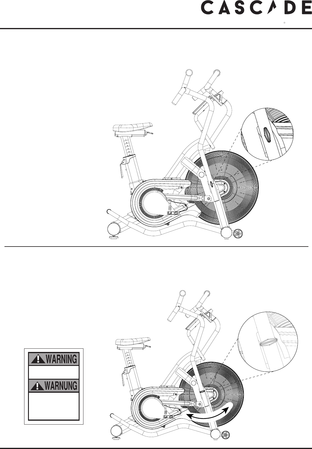
UN-LOCK - the dual arm while bike in use
Pull & twist the T knob.1.
Make sure the T knob is located parallel with the dual arm.2.
Release the T knob in un-locked position as shown.3.
LOCK - the dual arm while bike not in use
Pull & twist the T knob vertically to the dual arm with right hand.1.
Guide the dual arm carefully to the locking position with left hand.2.
Release the T knob in locking position as shown.3.
Lock the equipment
when not in use.
Sperren Sie das
Trainingsgerät,
wenn es nicht in
Gebrauch ist.
13
HEALTH & FITNESS
R
23
cascadehealthandtness.com

Computer Instructions
Quick Start
Button Functions
“Interval” and “Target” Program buttons
•
Immediately take you to the corresponding
workout selected.
stop
•
To nish or pause a workout. Press and hold
to reset the computer.
start
•
To begin a workout or restart a paused
program
•
To decrease values. Press and hold for rapid value change.
enter
•
To conrm the settings.
•
To increase values. Press and hold for rapid value change.
“If you stop pedalling without pressing the STOP button, after 30 seconds the program will automatically pause. You can resume
the program by pedalling again. After 3 minutes of inactivity the program will end.”
14
cascadehealthandtness.com
INTERVALREADOUTS
H.R.
target
HR
interval
20-10
interval
20-30
interval
custom
target
time
target
distance
target
calories
INTERVA
L
20/10
20/30
CUS
T
O
M
TO
TAL TIM
E
R
E
ST
TAR
G
E
T
TIME
DISTANC
E
C
AL
O
RIE
S
TAR
G
ET H
R
6
5
%
OF
8
0
%
O
F
M
AX
HR
X
BPM
N
O
HR
S
I
G
NAL
TAR
G
ET HR ACHIEVED
S
PEED
U
P
S
L
O
W D
O
WN
GO
TIME
?
DI
S
TANCE?
AVEMAX
R
PM / A
G
E?
CALORIES
?
T
OTAL
AVEMAX
SPEE
D
KP
H
MP
H
KM
MI
L
E
H
EART RAT
E
READY
R
EMAINING
E
LAPSED
stop enter start
WARNING : Heart rate monitoring systems may be inaccurate. If you feel faint, stop exercising immediately
A
VERA
GE
TO
TA
L
W
ATT
S
Use this mode if you just want a quick workout session and are not interested in setting up any personal data.
•
Pedal for a few seconds to power the console on.
•
Press the “ start “ button.
•
The values of WAT TS , SPEED, RPM, HEART RATE ( if heart rate signal is detected ) will start displaying.
•
The values of TIME, DISTANCE, CALORIES, WAT TS will start counting upwards.
Tonishthisquickworkoutsessionandviewyourworkoutsummary–
•
Stop pedaling.
•
Press the “stop“ button.
•
The values of TIME, DISTANCE, CALORIES, WAT TS, SPEED, RPM, HEART RATE
( if heart rate signal is detected ) will be displayed.
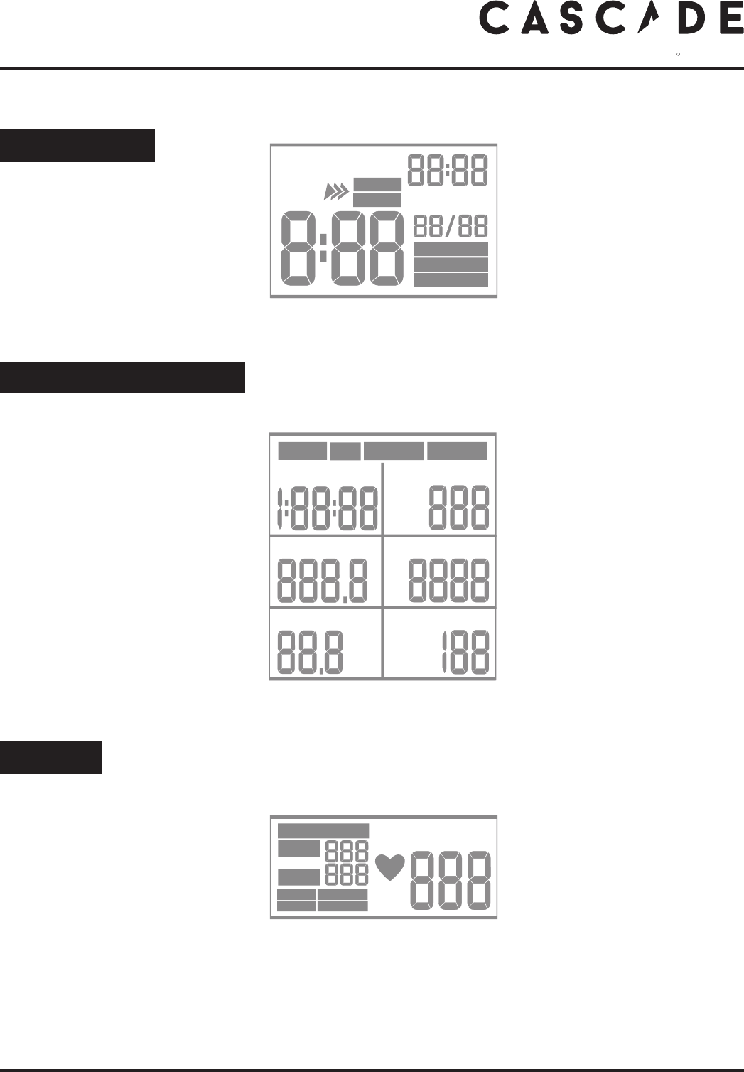
Console Display and Feedback
•
Indicates the INTERVAL 20/10 or INTERVAL 20/30 or
INTERVAL CUSTOM program is selected and in used.
•
Indicates the TARGET TIME or TARGET DISTANCE or TARGET CALORIES program is selected and in used.
•
Indicates the current heart rate in beats per minute (bpm), which are detected by a wireless heart rate chest belt.
INTERVAL
READOUTS
H.R.
•
Indicates the current section is in GO
period or REST period of the interval
program.
•
8:88 > Shows the count down GO or
REST segment time.
•
TOTAL TIME 88:88 >
Shows the count up GO & REST total
run time of the program.
•
88 /88 > Shows the current interval
and the total sections of intervals in
the program.
•
Indicates the approximate calories
burned this session ( for comparison
only, not to be used for medical pur-
pose), default counts up from zero to
999 kcal, but counts down if a target
had been set.
•
Indicates the current energy ( power )
generated this session, ( for compari-
son only, not to be used for medical
purpose) default counts up from zero
to 9999.
•
Indicates the current Revolutions
Per Minute you are pedalling at.
•
Indicates the target to exercise at 65% of
your maximum heart rate.
•
Indicates the target to exercise at 80% of
your maximum heart rate.
•
Indicates there is no heart rate signal
detected in this program.
•
Indicates the current heart rate is in the
target range.
•
Indicates the heart rate signal has been
detected.
•
Indicates an increased pedaling
speed is needed to bring the heart
rate into the target range.
•
Indicates an decreased pedaling
speed is needed to lower the heart
rate into the target range.
INTERV AL
20/10
20/30
CUSTOM
TOTA L TIME
REST
GO
READY
TA RGET HR
65%
OF
80%
OF
M
AX
HR
BPM
NO HR SIGNAL
TARGET HR ACHIEVED
SPEED UP
SLOW DOWN
HEART RATE
•
Indicates the time exercised this session,
default counts up from zero to 1:59:00 ,
but counts down if a target had been set.
•
Indicates the distance travelled this
session, default counts up from zero to
999.9 mile, but counts down if a target
had been set.
•
Indicates the current speed you are
pedalling at, in mile /h.
HEALTH & FITNESS
R
15
cascadehealthandtness.com
TA RGET
TIME
DISTANCE
CALORIES
TIME?
DISTANCE?
AVERAGE
TOTA L
AVEMAX
WATTS
RPM / AGE?
CALORIES?
TOTA L
AVEMAX
SPEED
KPH
MPH
KM
MILE

INTERVAL Programs
This console features 3 interval programs : interval 20/10,
interval 20/30 & interval custom.
The interval 20/10 and interval 20/30 programs oer users a series of
eight high-intensity workout intervals with preset timesegments.
These High Intensity Interval Training ( H.I.I.T.) programs will automati-
cally indicate the start of each GO & REST interval.
When you reach the last “ REST “ segment the console will sound a short
alarm and end the workout by coming to a stop.
Interval 20 /10 Program
1. Make sure the console is switched on.
2. Press the “ interval 20/10” to select the program mode
you want.
3. The default interval number of “ 0/08 “ is displayed in the
“ INTERVAL ” window.
4. The default time segment of “ REST 0: 10 “ is displayed
in the “ INTERVAL ” window.
5. Press “ enter ” to conrm your setting.
6. Press “ start ” to begin the workout and then start pedalling.
The program will not start until you begin pedalling.
NOTE: You can press the “ stop “ button to end the program at any time.
The workout summary will displayed on the screen.
Interval 20 /30 Program
1. Make sure the console is switched on.
2. Press the “ interval 20/30” to select the program mode
you want.
3. The default interval number of “ 0 /08 “ is displayed in the
“ INTERVAL ” window.
4. The default time segment of “ REST 0: 30 “ is displayed
in the “ INTERVAL ” window.
5. Press “ enter ” to conrm your setting.
6. Press “ start ” to begin the workout and then start pedalling.
The program will not start until you begin pedalling.
NOTE: You can press the “ stop “ button to end the program at any time.
The workout summary will displayed on the screen.
Interval custom Program
1. Make sure the console is switched on.
2. Press the “ interval custom” to select the program mode
you want.
3. Use the “ / “ buttons to set your GO segment time
( 0:01 ~ 9:59 minutes )
4. Press “ enter ” to conrm your setting.
5. Use the “ / “ buttons to set your REST segment time
( 0:01 ~ 9:59 minutes )
6. Press “ enter ” to conrm your setting.
Using Workout Programs
INTERV AL
20/10
20/30
CUSTOM
TOTAL TIME
REST
GO
READY
INTERV AL
20/10
TOTAL TIME
REST
INTERV AL
CUSTOM
TOTAL TIME
GO
INTERV AL
CUSTOM
TOTAL TIME
GO
16
cascadehealthandtness.com

7. Use the “ / “ buttons to set your total interval numbers
( 1 ~ 99 )
8. Press “ enter ” to conrm your setting.
9. Press “ start ” to begin the workout and then start
pedalling. The program will not start until you begin pedalling.
NOTE: You can press the “ stop “ button to end the program at
any time. The workout summary will displayed on the screen.
NOTE: You can press the “ enter “ button twice to save the set-
ting of this program after you complete the workout.
TARGET Programs
This console features 4 target programs : Target Time,
Target Distance, Target Calories & Target Heart Rate.
When you reach your target the console will sound a short alarm
and end the workout by coming to a stop.
Target TIME
1. Make sure the console is switched on.
2. Press the “ target time” to select the program mode
you want.
3. Use the “ / “ buttons to set your workout time
( 1:00 ~ 1:59: 00 minutes )
4. Press “ enter ” to conrm your setting.
5. Press “ start ” to begin the workout and then start
pedalling. The program will not start until you begin pedalling.
NOTE: You can press the “ stop “ button to end the program at
any time. The workout summary will displayed on the screen.
Target DISTANCE
1. Make sure the console is switched on.
2. Press the “ target distance” to select the program mode
you want.
3. Use the “ / “ buttons to set your target distance
4. Press “ enter ” to conrm your setting.
5. Press “ start ” to begin the workout and then start
pedalling. The program will not start until you begin pedalling.
NOTE: You can press the “ stop “ button to end the program at
any time. The workout summary will displayed on the screen.
INTERVAL
CUSTOM
TOTA L TIME
REST
INTERVAL
CUSTOM
TOTA L TIME
REST
TA RGET
TIME
DISTANCE
CALORIES
TIME?
DISTANCE?
CALORIES?
TOTA L
KM
MILE
REMAINING
ELAPSED
TA RGET
TIME
TIME?
TA RGET
DISTANCE
DISTANCE?
KM
MILE
HEALTH & FITNESS
R
17
cascadehealthandtness.com

Target CALORIES
7. Make sure the console is switched on.
8. Press the “ target calories ” to select the program mode
you want.
9. The default value of “ 50 “ is ashing in the “ CALORIES ”
window.
10. Use the “ / “ buttons to set your target calories
( 10 ~ 990 kcal )
11. Press “ enter ” to conrm your setting.
12. Press “ start ” to begin the workout and then start
pedalling. The program will not start until you begin pedalling.
NOTE: You can press the “ stop “ button to end the program at
any time. The workout summary will displayed on the screen.
Target HR Program
You need to be wearing a compatible wireless heart rate chest belt
to use this program.
Once you have entered your age the computer will calculate and
display the corresponding values for 65% and 80% of your maxi-
mum heart rate, whilst also displaying your current heart rate. The
computer will also prompt you to speed up or slow down to get
within the 65% to 80% zone.
1. Make sure the console is switched on.
2. Press the “ target HR ” to select the program mode
you want.
3. The default value of “30 “ is ashing in the “ AGE ” window.
4. Use the “ / “ buttons to input your age ( 10 ~ 99 )
5. Press “ enter ” to conrm your setting.
6. The default value of the 65% of Target HR & 80% Target HR is
displayed in HR window accordingly
7. Press “ start ” to begin the workout and then start
pedalling. The program will not start until you begin pedalling.
NOTE: You can press the “ stop “ button to end the program at
any time. The workout summary will displayed on the screen.
Do not use the Target HR program if your heart rate
is not registering properly on the display.
!
“NO HR SIGNAL” will ash in the HR window
if there is no wireless heart rate signal detected
when the program starts.
!
Please see the “ Exercising with your Air Unlimited ”
section for more details about the benets of
target heart rate training.
!
TA RGET HR
65%
OF
80%
OF
BPM
RPM / AGE?
HEART RATE
TA RGET
CALORIES
CALORIES?
18
cascadehealthandtness.com
TA RGET HR
65%
OF
80%
OF
BPM
NO HR SIGNAL
TIME?
DISTANCE?
AVERAGE
TOTA L
AV EMAX
WATTS
RPM / AGE?
CALORIES?
AV EMAX
SPEED
KPH
MPH
KM
MILE
HEART RATE

HEALTH & FITNESS
R
How to Take Care of Your Air Unlimited
Never remove the protective casing.
!
We do not recommend you attempt to service the internal parts of the pedal assembly.
If they are found to be worn internally, we recommend replacing the pedal.
!
Storage
Keep the equipment in a dry place with as little temperature variation as possible. Try to protect from dust and always unplug
when not in use (if applicable).
The safety level given by the design of this air bike can only be maintained when this air bike is regularly examined for damage
and wear. Inoperable components should be replaced immediately or this air bike should be put out of use until it is repaired
Your air bike is designed for indoor exercising used only and should not be used or stored in damp areas.
Ensure you regularly check components for wear and make sure all the nuts & bolts are tightened before each exercise session
Maintenance Tips
•
Always use a soft, cotton cloth and dilute non-abrasive cleaner or a mid detergent for cleaning the exterior of this bike.
•
Never use ammonia, acid-based, or petroleum-based solvents on any portion of the bike as it may damage the nish.
Preventative maintenance Schedule
Daily –
•
Before each use, make certain that the area around the bike is free of obstacles that may interfere with the dual action
handlebar & pedal rotation.
•
Before each use, check that pedals & shaft screws are securely tightened and inspect both pedals & pedal straps for wear.
•
After each use, wipe down the surface of the air bike to remove sweat and moisture.
•
Wipe the face of the display console with a slightly damp, soft, cotton cloth. Avoid getting extra moisture on the display
console. Keeping the display console free of ngerprints and sweat will extend the life of the console.
Weekly –
•
Thoroughly clean the plastic housing of the bike.
•
Clean the top of the pedal straps, saddle & seat post, and the display console.
•
Check that pedals are securely tightened and inspect both pedals and pedal straps for wear.
•
Inspect all assembly bolts & nuts for wear and ensure that they are suciently tight.
Monthly –
•
Make sure all of the open ends of metal parts are wiped with thin grease to protect from rust.
•
Check the ribbed belt is correct tension: replace cracked, frayed, or otherwise non-uniform belt.
If necessary, call your local authorized distributor for Customer Service replacement.
•
Inspect for side-to-side play in axle assembly , and a grinding feeling in crank area when pedaling.
If necessary, call your local authorized distributor for Customer Service replacement.
•
Check and Replace the Console AA Battery if needed.
•
Clean for dust on Fan Wheel Assembly by spray gun if available.
Use of lubricants or cleaning solutions other than those so specied will result in diminished
performance and a shorter life span for that part.
!
19
cascadehealthandtness.com

Exercising with Your Air Bike Unlimited
20
Always consult your doctor
before undertaking a new
exercise regime
If you experience nausea, dizziness or other abnormal
symptoms during exercise, stop at once and consult
your doctor
!
Correct cycling form
•
Sit on the cycle, with your feet on the pedals and inside the
pedal straps
•
Ensure that the seat height is adjusted correctly - you should
be stable and balanced whilst on the saddle. The basic rule
for getting the seat height right is that as the pedal reaches
its lowest point, the leg is almost straight.
•
Try to ensure that your back is straight whilst exercising,
especially for long periods.
How long should I exercise for?
That really depends on your current level of tness.
If you’re just starting out on a new exercise program, you
shouldstartgraduallyandbuildup–donottrytodotoo
much too quickly. 30 minutes,
3 times a week should be enough.
Don’t push yourself too hard - you should never feel
exhausted during or following exercise.
Heart Rate Training
To get the most out of your new piece of tness equipment
and see the best results from your training you should exercise
at the right level of eort, and that means listening to your
heart! Working out to a target heart rate means you can
direct your workout to achieve dierent goals:
Good health - For those wishing to improve quality of life
and general well being. Your sessions will need to be
done at an intensity of between 50-60% of your estimated
maximum heart rate, should last about 30 minutes and can
be done on most days of the week.
Weight loss
–Toseeasignicantreductioninbodyfat,your
sessions must be a little more intense - between 60 and
70% of your estimated maximum heart rate. These sessions
can also be performed on most days of the week for up to
30 minutes.
Improving Fitness levels
–Thesesessionsshouldbe
performed at 70-80% of your estimated maximum heart
rate and can also involve bouts of interval training that
would have your heart rate peaking for short times near
your maximum heart rate level. These are intense sessions
and will require at least a 48 hour rest between sessions.
Calculating your target heart rate
First, you need to nd your estimated maximum heart rate
using the formula ‘220 minus your age in years’. So, if you are
35 years old your estimated maximum heart rate is:
220 – 35 = 185 beats per minute (bpm)
Next, to calculate your target heart rate, simply multiply your
estimated maximum heart rate (185bpm) by the applicable
percentage. So, if your goal is better heath:
185 x 60% = 111bpm
NOTE: The important issue to remember with all
estimated calculations is that they are just estimates –
if you don’t feel comfortable exercising at your target
then reduce it to a level you are comfortable with.
!
Note: Heart rate training requires you to monitor your heart
rate throughout the workout. For this we recommend using a
chest strap (if your machine has a wireless receiver) or a heart
rate monitor.
Starting and nishing your workout
BeginandendeachworkoutwithaWarmUp/Downsession–afewminutesofstretchingtohelppreventstrains,
pulls and cramps
Troubleshooting
If you are having problems with your heart rate reading please note that some bres used in clothes eg) polyester, create static
electricity that may prevent a reliable heart rate reading. Mobile phones, TV’s, microwaves and other electrical appliances that
generate an electromagnetic eld may also interfere with heart rate measurement.
If you are still having problems with your equipment, please get in touch with your local distributor using the details found in
the Customer Support section on page 4.
If you have a problem with your equipment, before you do anything else please check that all
the cables have been connected correctly. Loose cables are very common and many problems
can be solved by making sure the cables are properly connected
!
cascadehealthandtness.com

21
Seat Adjustment
1. Seat Height:
•
Rotate the pedals so that one of the pedals is in the upward position.
•
Place your foot in the toe clip the pedal closest to the oor and mount the
bike. Ensure that the ball of your foot is over the center of the pedal. Your
leg should be slightly bent at the knee.
•
If your leg is too straight or your foot cannot touch the pedal your will need
to lower the seat. If your leg is bent too much you will need to raise the seat.
•
Dismount the bike and release / pull the seat post adjustment handle once
loosened you may slide the eat post up or down as necessary.
•
When the seat is in the desired position push the seat stem adjustment
handle forward to secure the seat post. Note the nal position mark on the
seat stem for future reference.
Seat Fore/Aft Position:
•
Adjusting the fore/aft allows for a better t. Dismount the bike
and pull the seat adjustment handle and slide the seat forward or
backward.
•
Sit on your bike with cranks in the 3 & 9 o’clock position. Proper fore/ aft
position is achieved when the small bump at the top of the shin directly
below the knee cap (tibial tuberosity) is approximately over the pedal axle
(at the 3 o’clock position).
•
Dismount the bike and release the adjustment handle to secure the seat.
2. Pedal Strap Adjustment:
The straps of the Air Bike Unlimited are designed to allow you to adjust
the pedal to your individual foot size. The pedal includes spring-loaded,
locking clips for easy adjustments. Follow the steps below to adjust the
straps so that your foot does not slip or slide about on the pedal.
•
Place the ball of each foot on the center of the pedal and under the
strap.
•
Rotate the pedals until one foot is in the position closest to you.
•
To tighten the straps, simply pull down on the end of the strap until it ts
snugly over your shoe. Make sure that the strap is secure, but not overly
tight or pressing uncomfortably on your foot.
•
Repeat these steps for the other foot.
•
To lossen the pedal strap, press down at the top of the clip that holds the
strap secure, and pull the strap up. Release the clip to lock the strap into
place.
3 .
•
Now that you have established a riding position, take a few minutes
to ride the bike and conrm that your position is comfortable. Start
pedaling at a slow pace with your toes and knees pointed directly
forward. Hold the grips lightly and in a position that allows your
shoulders and upper body to relax. Pedal easily at a low resistance
until your feel condent that you could ride in that position
comfortably for the duration of your workout.
WARNING: The equipment is not equipped with a free wheel and
therefore the moving parts cannot be stopped immediately.
155
O
NOTE: This product has an integrated speed
dependent resistance / braking system.
!
HEALTH & FITNESS
R
cascadehealthandtness.com

Exploded Diagram
22
cascadehealthandtness.com
A46
A47
A50
A51
A65
A54
A48
A49
A57
A55
J1
G
F
E2
J2
E
D1
A66
A20
A5
A27
A6
A67
A77
A76
A10
A11
B2*2
B
B3*2
B4*2
B1*2
B6*4
B5*2
D2-1
D2-2
D2-4
D2-3
D2
G
J1
H1
H2
J7
C
C1*2
C3*2
C2*2
A52
A36
A35
A73
A74
A36
A35
A40
A8
A2
A3
A1
A37
A7
A40
A37-1
J6
A44
A32
A31
A30
A80
A79
A78
A45
A43
A39
A41
J2
J5
I
J4
J3
A69
A9
A68
A70
A71
A13
A28
A29
A42
A72

23
Parts List
cascadehealthandtness.com
HEALTH & FITNESS
R
P/N DESCRIPTION Q'TY P/N DESCRIPTION Q'TY
A
Main Frame
1 A68
Front Fan Wheel Cover - L
1
A1
Ribbed Belt Wheel - OD360mm
1 A69
Front Fan Wheel Cover - R
1
A2
Ribbed Belt - 690 J7
1 A70
Chain Cover ( L )
1
A3
Magnetic ( OD15 X 7mm )
1 A71
Chain Cover ( R )
1
A5
Steel - Fan Assembly
1 A72
Sensor Housing
1
A6
Plastic Strip
1 A73
Phillip Head Self Tapping Screw ( M4 x 12mm )
4
A7
Shaped Crank Plate- L
1 A74
Phillip Head Self Tapping Screw ( M4 x 15mm )
4
A8
Shaped Crank Plate- R
1 A76
Plastic Strip Holder
2
A9
Hex Socket Head Cap Bolt ( M5 X 6mm )
4 A77
Phillip Head Machine Screw ( M4 X 10mm )
2
A10
Flat Washer ( M5 X Ø13 X 1T )
4 A78
Spring
1
A11
Hex Socket Head Cap Bolt ( M5 X 15mm )
4 A79
Gasket
1
A12
Hex Nut - M12
4 A80
Metal Plate
2
A13
Fan Wheel Axle Adjusting Screw Set - M8
2 B
Front Stabilizer
1
A20
Metal Spacer - Ø19 X Ø12.5 X Ø18.7mm
1 B1
Front Stabilizer End Cap
2
A27
Fan Wheel Axle ( OD12 X 155mm )
1 B2
Moving Wheel
2
A28
Seat Post Mounting Cap
1 B3
Allen Head Bolt ( M8 X 40mm )
2
A29
Seat Post Reducer Spacer
1 B4
M8 Capnut
2
A30
Allen Head Bolt ( M6 X 10mm )
2 B5
Foot Stop
2
A31
Metal Sleeve - ( Ø10 X 43.2mm )
1 B6
Phillip Head Machine Screw ( M4 x 12mm )
4
A32
Cam Handle
1 C
Rear Stabilizer
1
A35
Crank Arm Cover ( R + L ) - Large
2 C1
Rear Stabilizer End Cap - Ø101.6
2
A36
Crank Arm Cover ( R + L ) - Small
2 C2
Height Adjustable Lock
2
A37
Crank Axle - M25 X P1.5
1 C3
Height Adjustable Foot Stop - Ø50
2
A37-1
C-Clip S25
1 D1
Dual Action Handle Bar ( L )
1
A39
Crank Arm Assembly ( L )
1 D2
Dual Action Handle Bar ( R )
1
A40
Spacer ( Ø25 X 31 X T2mm )
1 D2-1
Lock Pin Knob
1
A41
Hex Socket Head Cap Bolt ( M8 X 40mm )
2 D2-2
Lock Pin Axle Keeper
1
A42
Bearing - 6005ZZ
4 D2-3
Lock Pin Spring
1
A43
Axle Adapter Washer
1 D2-4
Lock Pin Axle
1
A44
Hex Socket Head Cap Bolt ( M6 X 20mm )
1 E
Console Support Frame
1
A45
Metal Stop
1 E2
Bottle Holder (W/Screw)
1
A46
Saddle ( LS-A22 )
2 F
Console Assembly
1
A47
Saddle Base
1 G
Foot Peg
2
A48
Nylon Locknut - M8
3 H1
Pedal Set - L
1
A49
Spring Washer - M8
3 H2
Pedal Set - R
1
A50
Seat Post
1 I
Fixing Plate
2
A51
Hex Socket Head Cap Bolt ( M6 X 16mm )
1 J1
End Cap
2
A52
Phillip Head Self Tapping Screw
1 J2
Hex Socket Flat Head Bolt ( M8 X 30mm )
4
A54
Square End Cap
1 J3
M8 Nylon Locknut
2
A55
Adjustment Grip
1 J4
Disc Spring Spacer
2
A57
Hex Socket Flat Head Machine Screw(M6X15)
1 J5
Hex Socket Flat Head Machine Screw ( M6 X 15mm )
6
A65
Hex Socket Head Cap Bolt ( M6 X 35mm )
1 J6
Allen Head Bolt ( M10 X 20mm )
8
A66
Steel - Fan Wheel Cover - L
1 J7
Hex Socket Head Cap Bolt ( M6 X 8mm )
2
A67
Steel - Fan Wheel Cover - R
1

24
I - 1 Console Assembly
Speed Sensor x 150 m/m
Sensor Wire x 750 m/m
Console Connect Wire x 550 m/m
2 PIN
2 PIN
2 PIN
2 PIN
2 PIN
cascadehealthandtness.com

Cascade Health and Fitness Warranty
LABOR
FRAME LIFETIME
NON WEARABLE PARTS 5 YEARS
ELECTRONICS 2 YEARS
PEDALS 2 YEARS
WEARABLES 2 YEARS
Return Authorization #
prior to shipment
Your Billing Address
WARRANTY
PARTS
1 YEAR FOLLOWING
CUSTOMER INSTALLATION
NEED ASSISTANCE? Customer Service: (425) 402 - 4062
Prior to contacting our Customer Service Department, please have the following
information:
Your name, Customer Number, Shipping Address & Telephone Number
Serial Number(s) of the inoperable bike(s)
Date(s) of Purchase for the inoperable bike(s)
The above information will ensure that you are the only one ordering parts under
your warranty protection. If warranty replacement parts are shipped to you,
you may be
required to return the inoperable part(s). To facilitate this process,
the following policy has been established:
Contact our
Customer Service Department
to receive a
instructions. These instructions will be sent along with your warranty
replacement part (s)
Cascade will incur all UPS Ground freight charges for Warranty Parts ordered
for a machine that is less than 90 days old. You are responsi
ble
for freight
charges on warranty parts for machines that are more than 90 days old. You
will not be responsible for freight charges for any returned inoperable parts.
If an inoperable warranty parts(s) must be returned to our Customer Service
Department, we will pay the shipping cost and provide detailed return shipping
25
cascadehealthandtness.com
HEALTH & FITNESS
R

HEALTH & FITNESS
R
