
READ MANUAL BEFORE OPERATING SYSTEM
for your new
OWNER'S MANUAL
PN-9601 03/13
TO THE OWNER:
Read the owner's manual thoroughly to ensure the most
efficient use of your DIRT DEVIL
®
system.
THIS APPLIANCE IS FOR RV USE.
Please be sure this manual/installation
information is left with the power unit or
customer when installation is completed.
CV1500
HIGH PERFORMANCE CENTRAL CLEANING SYSTEM
FOR RV APPLICATIONS

1
IMPORTANT SAFETY INSTRUCTIONS
READ ALL INSTRUCTIONS BEFORE USING THIS VACUUM SYSTEM
WARNING
To reduce the risk of fire, electric shock or injury:
When using an electrical appliance, basic precautions should always
be followed, including the following:
• Unplug and disconnect power
before servicing.
• Do not use on wet surfaces.
• Do not allow to be used as a toy.
Close attention is necessary when
used by or near children.
• Use only as described in this
manual. Use only manufacturer's
recommended attachments.
• Do not use with damaged cord or
plug. If appliance is not working
as it should, has been dropped,
damaged, left outdoors, or
dropped into water, return it to a
service center.
• Do not pull or carry by cord, use
cord as a handle, close a door on
cord, or pull cord around sharp
edges or corners. Do not run
appliance over cord. Keep cord
away from heated surfaces.
• Do not unplug by pulling on cord.
To unplug, grasp the plug, not the
cord.
• Do not handle system or appliance
with wet hands.
• Keep hair, loose clothing, fingers,
and all parts of body away from
openings and moving parts.
• Do not put any object into open-
ings. Do not use with any open-
ing blocked. Keep openings free
of dust, lint, hair, and anything
that may reduce air flow.
• Do not pick up anything that is
burning or smoking, such as
cigarettes, matches, or hot ashes.
• Connect to a properly grounded
outlet. See grounding instruc-
tions.
• Turn off all controls before
unplugging.
• Use extra care when cleaning
on stairs.
• Do not use to pick up flammable
or combustible liquids such
as gasoline or use in areas where
they may be present.
• Do not place or store anything
on top of power unit - over-heating
of motor could occur.
• Any service work required
under the motor cover should
be performed by an authorized
service representative.
• Do not use without dust bag and/
or filters in place.
• Always turn off this appliance
before connecting or
disconnecting motorized nozzle.
SAVE THESE INSTRUCTIONS
FOR RV USE

3
GROUNDING
INSTRUCTIONS
This appliance must be grounded. If it
should malfunction or breakdown, grounding
provides a path of least resistance for electric
current to reduce the risk of electric shock.
This appliance is equipped with a cord having
an equipment grounding conductor and
grounding plug. The plug must be plugged
into an appropriate outlet that is properly
installed and grounded in accordance with
all local codes and ordinances.
WARNING
Improper connection of the equipment-
grounding conductor can result in a risk
of electric shock. Check with a qualified
electrician or service person if you are in doubt
as to whether the outlet is properly grounded.
Do not modify the plug provided with the
appliance - if it will not fit the outlet, have a
proper outlet installed by a qualified electrician.
The Model CV1500 appliance is for use on a
nominal 120 volt circuit and has a grounding
plug that looks like the plug illustrated in Fig. A.
Make sure that the appliance is connected to
an outlet having the same
configuration as
the plug. No adapter should be used with
this appliance.
Connect to a properly grounded outlet only.
Figure A
Grounding Method
WARNING:
ELECTRIC SHOCK
COULD OCCUR
IF USED ON WET
SURFACES.
CAUTION:
DO NOT USE ON
WET RUG OR
FLOOR.

4
Inserting hose into valve (Fig.B). Lift lid on
valve. Power unit will automatically come
on. Insert hose into valve. Connect desired
attachment and you are ready to vacuum.
Changing Bag (Fig. B). To keep your
CV1500 at top efficiency, change the filter
bag at regular intervals. Since cleaning
schedules differ, check frequently in the
beginning to determine proper interval.
To maintain cleanability, replace filter bag
when it is 2/3 to 3/4 full.
To Change the Filter Bag (Fig.B).
Locate canister, lift lid and pull bag collar
off connector. Open new bag, (expand
pleats by gently pulling on the bag). Slide
collar securely onto the inlet
connector. (See Fig.B) Replace with
Bag #9597.
To remove secondary #4929 Filter
& #4928/4934 Filter Supports for
Cleaning (Fig.B) Take out bag #9597,
pull support 4934 off connector and out
of canister. Take out 4929 & 4928. For
reassembly, follow instructions in reverse
order.
NOTE: 4929 filter wraps to front of 4928
filter support (Fig.B).
NOTE: This appliance has a THERMAL
PROTECTOR built into the motor to prevent
overheating. If motor will not operate, pull
power cord plug out of receptacle then
reinsert to reset.
If motor brushes or bearings are worn out,
the thermal protector will trip off again
after a short period of time. If this happens,
service for this and any other servicing
should be performed by an authorized
service representative.
WARNING: This unit must be installed in an accessible area with interior vent (Fig D).
AVERTISSEMENT: Cet unité devrait être installé dans un endroit bien aéré et accessible
afin d'éviter la surchauffe de L'appareil.
The Dirt Devil® CV1500 can be installed in any one of four configurations. Figures C, D & E illus-
trate three configurations, with C being the most common. The one not shown is a variation of D.
CV1500 OPERATING INSTRUCTIONS
CV1500 INSTALLATION INSTRUCTIONS
1. Locate unit centrally so that area to be
cleaned can be conveniently reached
with standard 20' or 30' hose. Also lo-
cate near grounded electrical receptacle
for easy plug-in connection of motor
cord. Route supply cord so that it
doesn't rest against sharp edges or pinch
points. See grounding instructions on
page 3.
2. All dimensions that follow are
approximate. To determine best
configuration for your installation,
temporarily install unit for best
valve location. Be sure there is
clearance to remove top cover and
filter bag.
continued onto next page
Figure: B
9597 Bag
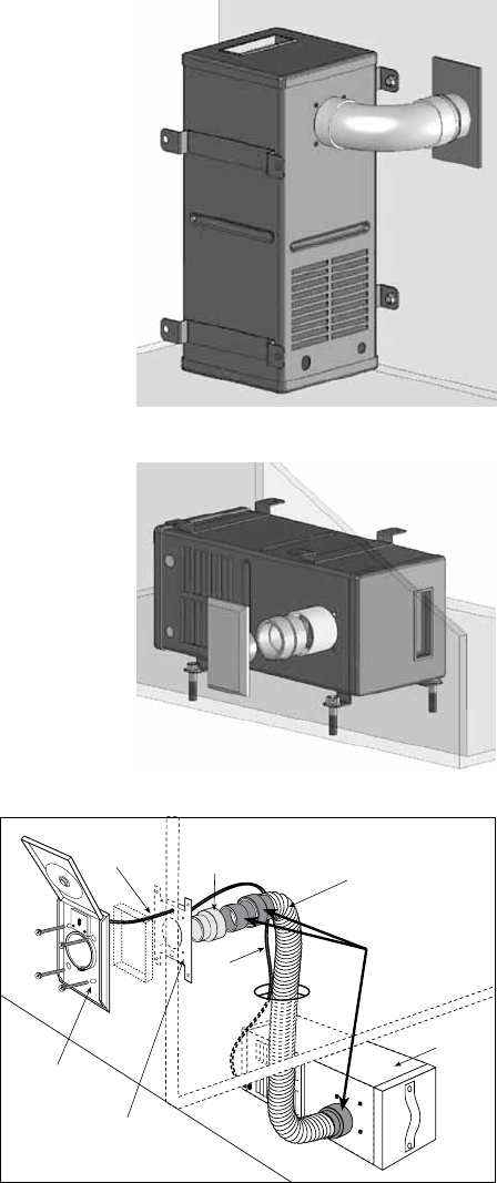
INSTALLATION INSTRUCTIONS continued...
7477-G
Flex Connector Kit
(3 Fittings)
5531 Inlet Reducer
6452-05
1¹⁄₄” Hose Cut to Length
CV1500
4940, 4935, 4941
Inlet Valve
4865 Mounting Plate
Wire
Wire
5
3.
Determine valve location and cut 2
1
/4"
(58mm) wide x
3
3
/4"
(95mm) high
opening,
9
7
/8"
(251mm) above the floor
(Fig C) for upright canister position or
1
3
/4"
(45mm) above floor for horizontal
canister position (see fig D).
4. Do not vent into a wall, ceiling or con-
cealed space of a building or structure.
Unit must be vented with interior vent
or equivalent (see fig D).
5. Place the CV1500 canister in its approxi-
mate location before installing inlet valve
(4940), mounting plate (4865), and
inlet reducer (5531) (see fig. E).
6. Inlet valve switch should be wired at this
point for convenience (See Figure E). In-
sert pre-stripped ends of 18-2 (1.00 mm-
2) low voltage wire into holes on back
of inlet valve (4940), press in firmly and
wires will lock automatically. Pull lightly
to test for locking. Connect other ends
of wire from inlet valve to wire leads
from relay (7090) with wire nuts provided.
7. Install inlet reducer (5531) to inlet con-
nector (7464), glue if needed. Assemble
inlet valve to wall with mounting plate
(4865) using the four screws provided
(see Figure E). Also, tabs on mount-
ing plate should face away from inlet valve.
8. Secure unit to floor and or wall with
mounting screws provided.
9. Plug in power cord from
motor unit to nearby elec-
trical receptacle. Route
power supply cord so that
it doesn't rest against
sharp edges or pinch
points. The CV1500
unit operates when the
inlet valve lid is lifted.
Figure: C
Figure: D
Figure: E
VACPAN
™
OPERATING INSTRUCTIONS
VACPAN
™
INSTALLATION INSTRUCTIONS
6
Simply switch on the VacPan automatic dustpan by pushing the raised tab with your foot.
Switching on the VacPan activates your central vacuum. Brush dirt and debris toward
the VacPan. When cleaning is complete, switch off the VacPan and the central vacuum
system by pushing the raised tab with your foot.
1. VACPAN requires a minimum 2-1/4" toe kick height.
2. Once the VACPAN location is determined, cut a 6-3/4" long x 1-3/4" high slot in
the cabinet toe kick to accept the VACPAN.
3. Run vacuum tube piping and low voltage wire from the main piping line to the
VACPAN location.
4. Access for final piping connections must be made. From below, cut an access hole
underneath the cabinet, positioned so that final piping connections can be made
through the access hole. Allow for 1/2" vertical play in vacuum tube piping at Vac-
Pan location so that final piping connections can be made.
5. Attach low voltage wires to the VACPAN terminal connections marked "low voltage
only".
6. Prior to final installation, check for an airtight seal between the VACPAN and elbow.
Teflon tape may be used if required.
7. Slide VACPAN into mounting slot and secure to toe kick using the two #6 screws
provided.
8. Reach through the access hole and make final piping connections.
VACPAN
™
II
OPERATING INSTRUCTIONS
VACPAN
™
II
INSTALLATION INSTRUCTIONS
VacPanII can be used as both an automatic dustpan and a standard hose inlet.
For automatic dustpan operation, slide top cover up, creating a sweep opening and
automatically switching on central vacuum system. Sweep material into opening. When
complete, slide top cover down, automatically shutting off central vacuum system.
For Standard Hose Inlet operation, ensure top cover is in fully lowered position. Grasp
side finger grips in top cover and flip top cover up. The top cover will lock out of the way.
Lift sprung flapper door open and insert central vacuum hose. Use your central vacuum
hose as you would with any other standard inlet valve.
1. VacPanII Wall Mount can be installed inside any wall with a minimum stud width
of 2-3/4".
2. VacPanII should be located against wall stud.
3. Once the VacPanII location is determined and prior to applying the wallboard,
attach Standard Mounting Bracket to the wall stud so that the center of the
mounting plate is 4" above the subfloor.
4. Attach VacPanII base stopper bracket, thereby allowing appropriated space for
final installation.
5. Run vacuum tube piping and low voltage wire from the main line to VacPanII
location and attach to mounting bracket.
6. Snap off two protruding tabs of VacPanII base stopper bracket and discard.
7. Align VacPanII with mounting bracket. Height adjustment may be required
depending on finished floor.
8. For VacPanII height adjustment: The body can be shortened by scoring along
Quick-Trim Grooves on back of body. The two-piece front cover can be adjusted
for height by twisting apart and engaging the mating teeth of the two parts. The
VacPanII entrance ramp can be slid on mating body grooves.
9. Attach low voltage wires to VacPanII terminal connections.
10. Slide VacPanII into mounting bracket and secure to wall using two #10 x 1-1/2"
screws provided. CAUTION: Do not over-tighten mounting screws as VacPanII
operation can be affected.

CV1500
PARTS LIST
# Part # Name Qty.
1 7759 Top Cover 1
1a 7764-DD Product Label 1
1b Handle 1
1c Gasket 1
2 9597 Bags (3 pack)
3 4934 Support - Side 1
4 4929 Filter - Secondary 1
5 4928 Support - Bottom 1
6 8728 Canister 1
7 7464 Inlet Connector 1
8 7455 Gasket 1
9 7655-01 Screw 4
11 7599-01 Bushing L.Volt Wire 1
12 7110-01 Power Cord 1
13 7758 Gasket - Motor 1
14 9590 Motor 1
15 9591 Bracket - Motor 2
17 6678 Bottom Cover 1
18 7064-02 Screw 5
19 7090 Relay Assy 1
28 7775 Screw 4
29 5148-6 Low Volt Wire (6 ft)
30 5149 Wire Nut 2
31 9601 Owners Manual 1
32 7539-02 Ground Screw 1
33 5737-03 Ground Wire 1
34 7108 Hex Nuts 3
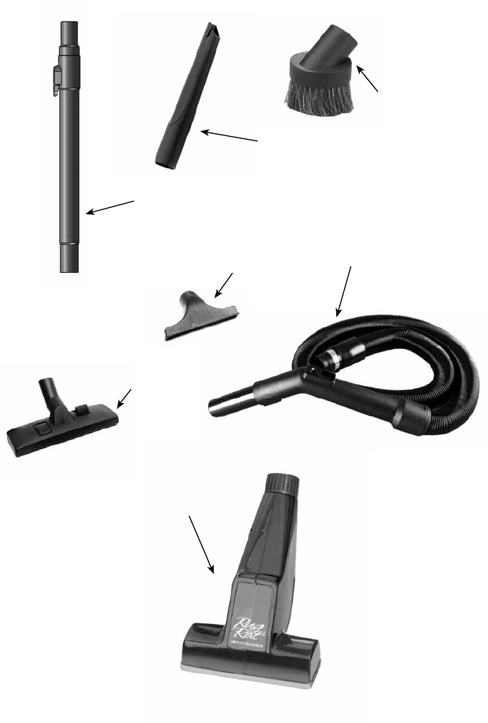
CV1500
ACCESSORY LIST
7029-B
Upholstery Tool
9090-B Rug/Floor Tool
9091-B Wand
9092-35 Hose Assembly
1142-B Dusting Tool
1141-B Crevice Tool
6972-BG RugRat Turbine
Power Brush (Optional)
