
Journal of Advanced Marine Engineering and Technology, Vol. 45, No. 5, pp. 252~262, 2021
ISSN 2234-7925 (Print)
J. Advanced Marine Engineering and Technology (JAMET)
ISSN 2765-4796 (Online)
https://doi.org/10.5916/jamet.2021.45.5.252
Original Paper
This is an Open Access article distributed under the terms of the Creative Commons Attribution Non-Commercial License (http://creativecommons.org/licenses/by-nc/3.0), which permits unrestricted
non-commercial use, distribution, and reproduction in any medium, provided the original work is properly cited.
Copyright ⓒ The Korean Society of Marine Engineering
Effects of blade number and draft tube in gravitational water vortex
power plant determined using computational fluid dynamics simulations
Min-Sung Kim
1
ㆍ Dylan S. Edirisinghe
2
ㆍ Ho-Seong Yang
3
ㆍ S. D. G. S. P. Gunawardane
4
ㆍ Young-Ho Lee
†
(Received October 7, 2021; Revised October 24, 2021;Accepted October 24, 2021)
Abstract: In recent times, gravitational water vortex power (GWVP) technology has shown rapid development because of its simple
design and adaptability to a wide range of flow conditions, even for low-head hydropower applications. In this study, the performance
of a GWVP plant was investigated, particularly with respect to the blade number in the vortex turbine and draft tube added as a
modification of the conical-shaped vortex basin. Computational fluid dynamics (CFD) simulations have been extensively used to assess
hydraulic efficiency while observing the flow field. The ANSYS CFX software was used as the simulation tool, and the CFD setup
was validated prior to simulating the newly designed GWVP plant. The effect of the blade number in the vortex turbine was investigated
using, 5-,6-,8- and 10-blade turbines, while the effect of the draft tube was studied using straight and conical designs. Finally, the eight-
blade turbine achieved a maximum efficiency of 57% while maintaining a stable vortex air core. The addition of a small draft tube in
the vortex basin increased the efficiency up to 60%, as it was able to recover the pressure gradually at discharge.
Keywords: Micro hydro, Water vortex, Turbine blades, CFD, Draft tube, Efficiency
1. Introduction
In recent times, the development of gravitational water vortex
power (GWVP) technology has been very rapid, with much
research being conducted regarding optimization of the vortex
basin and turbine designs. The reason for the advanced
development of this technology is the sustainability of the GWVP
plant compared to other commercial small-scale hydropower
extraction methods. Thus, vortex power plant designs can be
adapted to suit a wide range of flow conditions involving smaller
hydraulic heads. As the power plant design is a run-of-the-river
system, no water storage reservoir is required, thus minimizing
the environmental impact [1]. In addition, it can ensure water
purification by aeration by increasing the oxygen concentration
of the water [2]. On the other hand, this technology can be
implemented in hillside areas enriched with hydro-potential to
power up rural communities that are situated far away from the
electricity distribution grid. Therefore, GWVP plants can be used
to support rural communities, thereby providing social benefits
[3]. Thus, the installation and maintenance of a GWVP plant is
simple and cost-effective [4]. Therefore, according to the three
pillars of sustainability (economic, environmental, and social),
GWVP plants are a viable solution in the hydropower extraction
sector. Franz Zotlöterer implemented the vortex power extraction
method using the basic concept of Viktor Schauberger, which
utilizes the natural energy stored in the water to form vortexes
[5]. Initially, Zotlöterer used a water vortex to aerate the water
without employing any external power. Later, he used a vertical
axis rotor at the vortex center to generate rotary energy [6].
In the GWVP plant, gravity-driven water is guided in a tan-
gential direction to a circular basin structure called a vortex basin
with a bottom center outlet. Therefore, inside the vortex basin,
water creates a strong vortex around the vertical-central axis. Us-
ing the vertical axis turbine, the vortex power generated can be
extracted as mechanical energy and later converted to electrical
energy through the use of generators. Figure 1 illustrates the
GWVP plant design used in this study, showing the main
†
Corresponding Author (ORCID: https://orcid.org/0000-0001-9598-6172): Professor, Division of Mechanical Engineering, Korea Maritime &
Ocean University
, 727, Taejong-ro, Yeongdo-gu, Busan 49112, Korea, E-mail: lyh@kmou.ac.kr, Tel: +82-51-410-4293
1
Ph. D. Candidate, Department of Mechanical Engineering, Korea Maritime & Ocean University, E-mail: kimms4u@naver.com
2
Ph. D. Candidate, Interdisciplinary Major of Ocean Renewable Energy Engineering, Department of Mechanical Engineering, Korea Maritime &
Ocean University, E
-mail: dylanzenith@gmail.com
3
Ph. D. Candidate, Interdisciplinary Major of Ocean Renewable Energy Engineering, Department of Mechanical Engineering, Korea Maritime &
Ocean University, E
-mail: kp[email protected]mou.ac.kr
4 Professor, Department of Mechanical Engineering, University of Peradeniya, Sri Lanka, E-mail: [email protected]

Min-Sung Kim ㆍ Dylan S. Edirisinghe ㆍ Ho-Seong Yang ㆍ S. D. G. S. P. Gunawardane ㆍ Young-Ho Lee
Journal of Advanced Marine Engineering and Technology, Vol. 45, No. 5, 2021. 10
253
components. The vortex basin and vortex turbine are the main
components of a GWVP plant. Therefore, the GWVP plant de-
sign is developed mainly by optimizing the structure of the vor-
tex basin or the design of the vortex turbine. Although several
studies have been conducted using various optimization proce-
dures, GWVP technology is accepted as a relatively new technol-
ogy, as no standard design procedure is available.
Dhakal et al claimed that the design of the conical shaped vor-
tex basin performs better in terms of efficiency than the cylindri-
cal basin, in the same position of the turbine [7]. It is recom-
mended that the water flow from the inlet channel to the basin be
as tangential as possible because it causes fewer distortions and
prevents unnecessary losses [8][9]. The inlet design of most vor-
tex basins is either tangential or scroll with a flat bottom. The
scrolling inlet is more commonly used as it increases the dis-
charge gradually, spiraling along the basin towards the drain out-
let [10]. Thus, for a cylindrical-shaped basin, Choi et al suggested
a ratio for the optimal bottom outlet orifice diameter to basin di-
ameter in the range of 17-18.5% [11]. The vortex strength and
stability depend greatly on this diameter ratio, with the formation
of a central air core [12]. Smaller diameter ratios block the outlet,
thus preventing air core formation, while the ratios for larger di-
ameters release water without circulation. In both cases, it tends
to reduce the vortex strength [10].
The vortex turbine is closer to the impulse-type turbine than to
the reaction-type turbine because it does not work on the pressure
differential, but rather on the dynamic force of the water vortex
[2][13]. When the turbine is inserted into the vortex basin, the
vortex is disturbed by the turbine blades, thus decreasing the
tangential velocity component of the water while increasing the
axial velocity component [2][14]. Several studies have been con-
ducted to optimize the blade profile geometry. Dhakal et al [15]
demonstrated that a horizontal curved blade profile was the most
efficient. However, Saleem et al [14] reported low performance
for horizontal curved blades because the tangential velocity com-
ponent that was affected resolved into components, and only one
component contributed to the blade rotation. In fact, Bajracharya
et al [16] studied the effect of several blade parameters on turbine
performance in terms of the impact angle, blade angle in the ver-
tical and horizontal planes, taper angle, height, cutting of the
blade, and number of blades. The study is concluded by recom-
mending a ratio of 0.31-0.32 blade height to basin height, 20°
impact angle, and taper angle conforming to the basin cone angle
and blade at a horizontal angle of 50° to 60°.
The bottom-most position inside the vortex basin is accepted
as the best place to locate the turbine in a conical basin because
the vortex strength is at its highest at the drain orifice [13][17].
Dhakal et al [17] claimed a decline in the performance when the
number of blades in the turbine increased from six to 12; how-
ever, Christine Power et al [18] claimed heightened performance
when the number of blades was increased from two to four. The
number of blades or guide vanes is one of the most important
parameters in the design of hydro turbines [19]. The optimal
number of blades in a vortex type turbine depends on the strength
of the formed vortexes and several other factors, especially the
friction losses. Generally, in vortex phenomena, the air-core ra-
dius decreases gradually from the free surface to the bottom ori-
fice [20][21]. However, in the presence of the turbine, the air core
behavior becomes more complex. Furthermore, a larger turbine
hub diameter is not recommended because it tends to disturb the
air core formation and the vortex shape without gaining power
[14]. Finally, more complicated flow behavior occurs inside the
GWVP plant, influenced by many factors [12], especially the be-
havior of the air core and friction losses.
The GWVP plant in this study was designed based on the find-
ings of the studies cited above, while adapting them for a selected
installation site. As one of the objectives of the current study, the
CFD flow field was observed to identify the effect exerted by the
number of blades in the vortex turbine, while improving the con-
ical basin design provided with a small draft tube. Computational
fluid dynamics (CFD) was extensively used in this study to sim-
ulate and analyze the flow field in each case, with an assessment
of the performances.
Conical
basin
Scroll
guide
Generator
Gear ar-
rangement
Turbine
Draft tube
Figure 1: GWVP plant design

Effects of blade number and draft tube in gravitational water vortex power plant determined using computational fluid dynamics simulations
Journal of Advanced Marine Engineering and Technology, Vol. 45, No. 5, 2021. 10
254
In the first section of this article, the GWVP plant is introduced
with a brief literature review on past researches; in the second
section, the fundamental concept regarding the vortex theory and
water velocity behavior in the GWVP plant is explained. In the
third section, the methodology, computational design, and simu-
lation procedure are described. In Section four, the performance
curves for different numbers of blades and draft tube cases are
presented. Validation of the CFD setup is discussed, as this study
was based on CFD simulations. Finally, in Section five, the sim-
ulated flow fields are analyzed using the water-air interface, ve-
locity vector, and pressure contour. Hence, utilizing the flow phe-
nomenon, the variations in performance are justified and dis-
cussed. In Section six, the conclusions of the study are presented,
citing the findings of the current study along with suggestions for
improvements.
2. Vortex Phenomena and Vortex Turbine
The formation of the water vortex is explained by applying the
angular momentum theory [10]. A fluid particle with a small an-
gular velocity but with a large radial position produces a signifi-
cant angular momentum. When the particle moves toward the
center, it gradually reduces the radial position while increasing
the angular velocity to conserve the angular momentum. There-
fore, at the central axis, the water flow creates a significant swirl,
called the vortex. Vortex systems are normally discussed in terms of
cylindrical coordinates, where the center axis is laid along the z axis
and the velocity vectors
,
θ
,
correspond to the radial () , tan-
gential () and axial () directions as shown in Figure 2.
By solving the Navier-Stokes equation in continuity and three
momentum equations with the assumption of steady, asymmetric,
and inviscid flows with axial derivatives as negligibly small, the
tangential momentum equation is simplified to the relationship
given below for the potential vortex shown in Equation 1.
=
(1)
where Γ is the circulation, defined as the line integral of the
tangential velocity component.
Therefore, in a vortex system, the tangential velocity compo-
nent dominates the flow field, where the radial and axial velocity
components are negligible. As the potential vortex model is not
suitable for describing the center of the vortex, Rankine proposed
a more reliable model, which was later used by many profession-
als for the development of reliable vortex models. In Figure 3,
the different vortex models followed by the Rankine and potential
vortex models are depicted. Furthermore, an air core was formed
at the center of the free-water vortex. The water vortex stability
depends on the formation of a continuous stable air core [10].
When the vertical-axis turbine is placed in the water vortex
field, the vortex is distorted by the turbine blades that extract the
vortex energy. The tangential velocity component of the vortex
contributes substantially to the power extraction, as it is the dom-
inant velocity component in the vortex. Initially, the vortex is
struck on the turbine blades, reducing its tangential velocity com-
ponents, while slightly increasing the axial and radial velocity
components. The vertical twisted blade profile of the turbine was
used to extract the excess energy from the axial velocity compo-
nent just prior to discharge.
As the energy is extracted chiefly from the tangential velocity
component of the water vortex, it is important to identify the
Figure 2: Cylindrical co-ordinate system used to de-
scribe the vortex phenomena
r
z
r
Potential vortex
Rankine vortex
Vatistas n=2 vortex
Scully vortex
Figure 3: Tangential velocity variation for different
vortex models

Min-Sung Kim ㆍ Dylan S. Edirisinghe ㆍ Ho-Seong Yang ㆍ S. D. G. S. P. Gunawardane ㆍ Young-Ho Lee
Journal of Advanced Marine Engineering and Technology, Vol. 45, No. 5, 2021. 10
255
effect of the number of blades. The number of blades in the vor-
tex turbine is strongly dependent on the strength of the vortex,
where the distance between the blades must be effective for re-
ceiving the power of the water flow onto the blades [5]. There-
fore, as one objective of this study, an optimal number of blades
was identified in the vortex turbine while observing the behavior
of the CFD flow. Another aspect of this study involved the anal-
ysis of the effect of different draft tube designs as an extension
of the modification of the vortex basin.
3. Design and Computational Modelling
3.1 Methodology
The design of the GWVP plant is highly dependent on recent
research findings and the site conditions, particularly the space
availability, flow, and hydraulic head. The design was developed
to recover the energy of wastewater discharged from a fish farm
located in the area called Namhae, on the southern coast of South
Korea. The average flow rate was recorded as 0.530 m
3
/s, and the
estimated hydraulic head was 2 m.
To compare the GWVP plant parameters, a three-dimensional
structural model was created for the vortex basin and turbine. Us-
ing the structural model, the fluid domains were extracted for
CFD simulations. As the CFD is based on finite element theory,
the fluid domains were meshed using ANSYS ICEM software.
Then, the fluid domains were set up in ANSYS CFX to define
the necessary boundary conditions. As this research is strongly
based on the CFD study, the validation process was initially per-
formed by comparing it with the experimental results of a recent
GWVP plant research, showing fair agreement.
In this study, two main cases related to the vortex turbine and
basin were analyzed. Under the effect of the number of blades,
four different cases were simulated having 5,6,8 and 10 blades.
Selecting the best turbine (with the most effective number of
blades) as the optimal turbine, the draft tube cases were further
studied. The effect of the draft tube was observed under four spe-
cific cases: no draft tube, straight draft, conical draft tube, and
height increased conical draft tube.
Hydraulic efficiency was used as the criterion to compare the
performance of the GWVP plant, which is denoted by the ratio
of the extracted power to the available hydraulic power, as ex-
pressed in Equation 2.
=
(2)
Generally, the available hydraulic power is calculated using
Equation 3,
=
(3)
where ρ is the density of water (998 kg/m3), g is the gravita-
tional acceleration (9.81 m/s
2
), Q is the volume flow rate, and H
is the hydraulic head, which is defined as the difference between
the inflow and outflow water level but not related to the vortex
height. H was calculated using the CFD post-processing, as
shown in Figure 4.
Figure 4: Hydraulic head and the maximum vortex height inside
the designed vortex basin
Extracted power is calculated using the Equation 4.
=
(4)
where τ is the torque on the turbine in Nm, which is monitored
during the CFD solving process. ω denotes the rotational speed
of the turbine in rad/s, which was predefined in the simulations.
3.2 Computer aided modeling
The width of the wastewater discharge channel is 1.3 m, at the
selected site. Considering it as the inflow channel to the GWVP
plant, this channel was made to converge to the vortex basin via
a scroll guide channel. Therefore, to facilitate the entry of water
into the conical-shaped part of the basin, the upper part of the
vortex basin was designed with a flat bottom. The maximum di-
ameter of the vortex basin was 3.6 m and the diameter of the bot-
tom discharge orifice was 0.6 m. Different draft tube designs
were then fitted to the drain orifice. Three types of draft tube
cases were observed: straight, conical, and increasing the conical
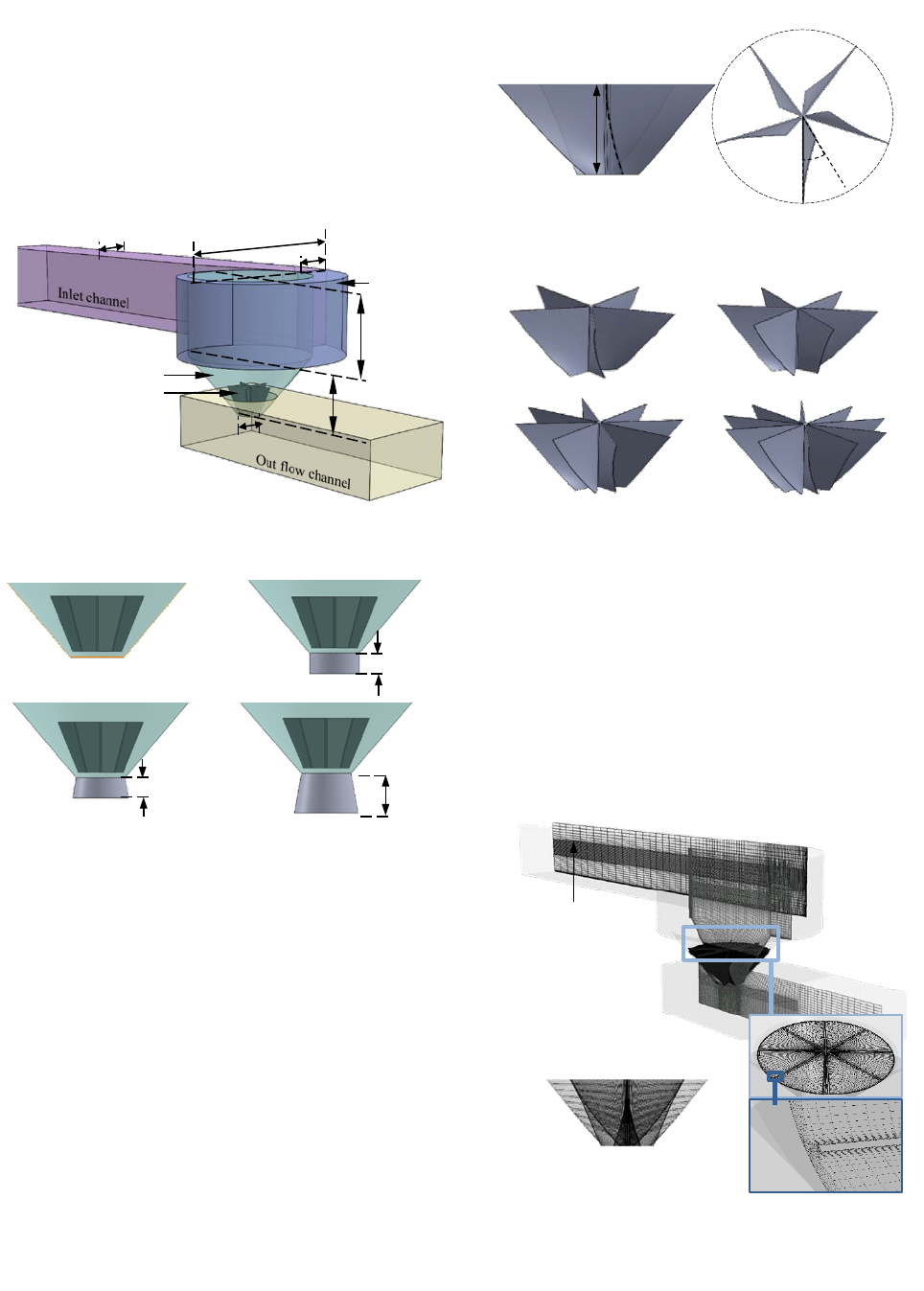
height, followed by no usage of the draft tube. In Figure 5, the
basic fluid model for the designed GWVP plant is illustrated, and
H
vortex
height
Hydrau-
lic head
Height of draft tube
Effects of blade number and draft tube in gravitational water vortex power plant determined using computational fluid dynamics simulations
Journal of Advanced Marine Engineering and Technology, Vol. 45, No. 5, 2021. 10
256
Figure 6 shows the difference between each of the simulated
draft tube designs. Although the estimated water height is 2 m,
the model was extended further, allowing it to adapt to the height
of the water level for different rotational speeds. An outlet chan-
nel was designed to observe discharge water flow after draining
out from the basin.
Figure 5: CAD model for designed vortex basin fluid domains
Figure 6: Different draft tube designs (a) no draft tube (b)
straight draft tube (c) conical draft tube- divergent angle 10
o
(d)
height increased conical draft tube
The basic vortex turbine model was designed to have five ver-
tical twisted blades matched with a conical shaped basin, having
0.7 m height. The twist angle was 30° between the top and bottom
blade profiles, where the twist was gradually increased from the
top to the bottom of the blade. In Figure 7, the basic turbine de-
noting the parameters of the blade profile is illustrated, whereas
in Figure 8 the 5,6,8 and 10 bladed turbines are shown. The tur-
bine hub diameter was maintained at 50 mm for every case, and
the gap between the inner wall of the basin and the blade tip was
maintained at 20 mm.
Figure 8: Different number of bladed turbines (b) five-bladed (c)
six-bladed (d) eight-bladed (e) ten-bladed
3.3 Computational fluid dynamic Simulation
The ANSYS 17.2 package was used to solve the CFD simula-
tions. The ANSYS ICEM software was used to create an unstruc-
tured hexagonal mesh for the fluid domains of the GWVP plant
provided with the necessary refinements, as shown in Figure 9.
Figure 9: (a) Hexagonal mesh of GWVP plant's fluid domains
(b) Mesh on the turbine blade surface (c) Mesh refinement near
blade wall and basin inner wall
Conical shaped
vortex basin
Turbine
Scroll guide
Pitch =0.95m
Revolution =0.76
1.3 m
0.9 m
1.15 m
3.6 m
1.5 m
0.6 m
(a)
Turbine
(b)
Turbine
0.2 m
(c)
Turbine
0.2 m
(d)
Turbine
0.4 m
(c)
(d)
(e)
(b)
30°
0.7 m
(a)
(b)
(b
(c
Mesh refinement
at free water surface
(a
Figure 7: Blade profile of the vortex turbine (a) Side view (b)
top view

Min-Sung Kim ㆍ Dylan S. Edirisinghe ㆍ Ho-Seong Yang ㆍ S. D. G. S. P. Gunawardane ㆍ Young-Ho Lee
Journal of Advanced Marine Engineering and Technology, Vol. 45, No. 5, 2021. 10
257
Special attention was paid to the mesh refinement near the wall
to capture the boundary layer effect and the free water-air inter-
face to distinguish a clear interface. The O-grid concept was ap-
plied to mesh the turbine fluid to refine the mesh around the blade
surfaces. The first layer thickness around the blade wall was 0.01
mm resulting in a maximum y
+
of approximately 15 on the blade
surface, indicating the reliability of the mesh around the blade.
The total number of mesh elements was 2.25x10
6
where 1.1x10
6
was in the turbine domain.
CFD simulation was performed using the ANSYS CFX tool.
Steady-state simulations were conducted for all cases that were
solved using the Reynold Average Navier –Stokes (RANS) equa-
tions. Thus, a homogeneous multiphase model was introduced to
define air and water. Gravity was defined as 9.81 m/s
2
and a den-
sity different buoyancy model and a free surface model were se-
lected because the water and air can be separated, rather than hav-
ing a mixture model. The surface tension coefficient was intro-
duced as 0.072 N/m, indicating that water was the primary fluid.
The reference pressure was set as the atmospheric pressure
(1atm).
Only the turbine domain is defined as a rotational domain that
rotates at a given rotational speed, whereas the rest of the do-
mains are considered as stationary domains. The interface be-
tween the rotational and stationary domains is defined as the gen-
eral grid interface (GGI) connection. The 530 kg/s bulk mass
flow rate was defined as the inlet condition for the inflow chan-
nel, while the outlet was defined as having a constant water level
given by the appropriate hydraulic pressure. The top surface of
the basin was defined as an opening with the same atmospheric
pressure. The basin walls, turbine blades, and shafts indicate a
no-slip smooth wall.
Figure 10: Boundary conditions of CFD set up for GWVP plant
simulation
In Figure 10, the boundary conditions for the CFD set-up are
summarized. Based on the recommendations of several studies,
the shear stress transport (SST) turbulence model was introduced
with circular correction [10]. Thus, the SST model is highly rec-
ommended for turbomachinery simulations because it produces
a more realistic solution. In solver control, the maximum itera-
tion was set to 5000, and the residual target was fixed at 1 × 10
5
.
The torque on the turbine blades was monitored during the pro-
cess of solving the simulations.
4. Results
4.1 Validated study
The experimental results of the Yasuyuki Nishi and Terumi
Inagaki vortex turbines [2] were used to validate the ANSYS
CFX setup. In this particular study, a turbine with twenty blades,
was installed inside a cylindrical vortex basin. A maximum effi-
ciency of 35 % was recorded in this configuration, and they com-
pared the simulation and experimental performance, where the
experimental results were used to validate the current CFD setup.
The basic dimensions of the validated vortex turbine are listed in
Table 1.
Table 1: Basic dimensions of validated vortex turbine model
Parameter
Value
Unit
Inlet channel width
0.1
m
Vortex basin diameter
0.49
m
Turbine outer diameter
0.14
m
Turbine inner diameter
0.09
m
Turbine height
0.091
m
Number of blades
20
-
Figure 11: Simulated water flow behavior for validated model
In Figure 11, the water flow behavior for the validated model
is illustrated,whereas in Figure 12, a comparison of the
efficiency of the validated CFD study with the experimental
study is shown. The variations in the validated efficiency showed
fair agreement with the experimental study, showing a slight
deviation in the efficiency for only two rotational speeds. As the
Bulk mass flow inlet =0.53kg/s
Up tank pressure
Up tank water VF
/Up tank air VF
Opening
Down tank pressure
Down tank water VF /
Down tank air VF
Opening, Ref. pressure =0 Pa, Water VF =0 /Air VF
1
Turbine
Air core prop-
agation
Cylindrical
basin
Effects of blade number and draft tube in gravitational water vortex power plant determined using computational fluid dynamics simulations
Journal of Advanced Marine Engineering and Technology, Vol. 45, No. 5, 2021. 10
258
maximum deviation was below 5%, the overall results of the
validation were recognized as suitable for simulating a new
model of the GWVP plant.
Figure 12: Validated efficiency comparison with reference ex-
perimental study
4.1 Performance of modified GWVP plant
The CFD simulations reached the steady state condition after
2000 iterations, despite being run further, up to 5000 iterations.
The values of the residuals for the u, v, and w momentums con-
verged to below 10
-3
and the mass imbalance was less than 2%.
The monitor point of the torque varied around a constant at a
value of 0.4% bandwidth. The GWVP plant performance was
measured using hydraulic efficiency, calculated using CFD sim-
ulations. The efficiency graphs were followed by variations in the
torque and hydraulic head. The variations in the torque were con-
sidered to be related to the extracted power for a given rotational
speed. The hydraulic head is related to the available power for a
constant flow rate. The effect of the number of blades in the vor-
tex turbine and the effect of the draft tube were observed for dif-
ferent rotational speeds, and the efficiency curves were con-
structed, as shown in Figures 13 and 14.
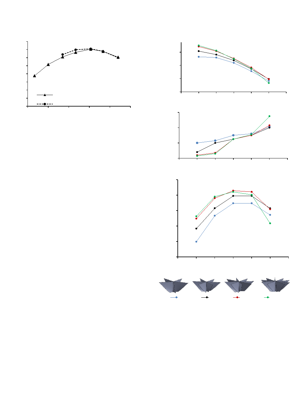
In the first part of the research, an investigation was conducted
on the effect of the number of blades in the vortex turbine. In
Figure 13, variations in the torque and hydraulic head, as well as
the CFD efficiency for different numbers of blades in the vortex
turbine are illustrated. The initial turbine had five blades and it
yielded 54% maximum efficiency, between 40-45 rpm. When the
number of blades was increased from five to eight, the peak effi-
ciency of the GWVP plant also increased, resulting in the highest
efficiency of 57.2%. However, when the number of blades was
increased from eight to ten no significant difference was ob-
served, but there was a slight reduction at higher rotational
speeds. The main reason for the increase in the efficiency of the
turbines with a higher number of blades is the increase in the
torque, accompanied by a slight decrease in the hydraulic head,
as shown in Figure 10.
Figure 13: GWVP plant performance for turbine consist with
different number of blades (a) Torque variation (b) Hydraulic
head variation (c) CFD efficiency variation
Figure 14 illustrates the variations in the torque and hydraulic
head, as well as the CFD efficiency for different draft tube de-
signs. The draft tube effect can be clearly observed, as it tends to
increase the efficiency by approximately 3%. The effects of the
straight and conical draft tubes remain almost unchanged follow-
ing the common trend curve of performance. In addition, any in-
crease in the height of the conical draft tube did not affect
0.00
0.05
0.10
0.15
0.20
0.25
0.30
0.35
0.40
30 60 90 120 150 180
Efficiency
Rotational speed (rpm)
Reference experiment efficiency
Validated efficiency
700
900
1100
1300
25 30 35 40 45 50 55
Torque (Nm)
Rotational speed (rpm)
1.67
1.69
1.71
1.73
25 30 35 40 45 50 55
Hydraulic head (m)
Rotational speed (rpm)
40
44
48
52
56
60
25 30 35 40 45 50 55
Efficiency (%)
Rotational speed (rpm)
NOB5 NOB6 NOB8 NOB10
Five
bladed
Six
bladed
Eight
bladed
Ten
bladed
(a)
(b)
(c)

Min-Sung Kim ㆍ Dylan S. Edirisinghe ㆍ Ho-Seong Yang ㆍ S. D. G. S. P. Gunawardane ㆍ Young-Ho Lee
Journal of Advanced Marine Engineering and Technology, Vol. 45, No. 5, 2021. 10
259
Figure 14: GWVP plant performance for different draft tube de-
signs (a) Torque variation (b) Hydraulic head variation (c) CFD
efficiency variation
the performance. The addition of the draft tube to the vortex basin
exerts its effect as it increases the torque of the turbine. This is
because it helps to maintain the low-pressure region at the bot-
tom-back side of the turbine blade, increasing the pressure drop
across the blade. This phenomenon is explained in detail in the
Discussion section.
5. Discussion
The performance of each of the simulated GWVP plant cases
can be justified using flow analysis in the CFD post process.
Three main parameters related to the flow were analyzed: water-
air inter phase (at 0.5 water volume fraction), water superficial
velocity, and pressure contours.
In the case of turbines with different numbers of blades, the
performance was observed to increase when the number of
blades was increased from five to eight. When the blade number
was increased, the turbine exposed a large area to the vortex, ex-
tracting a relatively large quantity of energy. Therefore, the
torque of the turbine increased at an optimal rotational speed be-
tween 40 and 45 rpm. On the other hand, no significant change
in the performance was noted when the number of blades was
increased to ten, even though the effective area of the turbine in-
creased significantly. This is because the ten-blade turbines
would block the water outflow while avoiding air core formation.
In the presence of the vortex turbine, the air core is parted and
propagated behind the turbine blade maintaining the low-pres-
sure region, while discharging at the circumference of the drain
outlet. Therefore, without the air core, the low-pressure region
was not maintained, and hence, the pressure drop across the tur-
bine blade was reduced. In Figure 15, the propagation of the air
core behavior for turbines with different numbers of blades
shows that turbines with fewer blades tend to maintain a larger
air core, while a higher number of blades in the turbines produce
only small air cores.
Figure 15: Water and air behavior for different numbers of
bladed turbine (water-air interface is defined by 0.5 water volume
fraction) (a) five-bladed (b)six-bladed (c) eight-bladed (d) ten-
bladed
48
50
52
54
56
58
60
62
25 30 35 40 45 50 55
Efficiency (%)
Rotational speed (rpm)
DT0 DTS DTC DTC_H400
850
1050
1250
1450
25 30 35 40 45 50 55
Torque (Nm)
Rotational speed (rpm)
1.67
1.68
1.69
1.70
1.71
1.72
25 30 35 40 45 50 55
Hydraulic head (m)
Rotational speed (rpm)
No
draft
tube
Straight
draft
(a)
(b)
(c)
Conical
draft
Height
increased
draft tube
(a)
(b)
(c)
(d)

Effects of blade number and draft tube in gravitational water vortex power plant determined using computational fluid dynamics simulations
Journal of Advanced Marine Engineering and Technology, Vol. 45, No. 5, 2021. 10
260
Figure 16: Water superficial velocity contour and velocity vec-
tor on quarter-horizontal cross section of the turbine (red circle
area denotes the circulation) (a) five-bladed (b)six-bladed (c)
eight-bladed (d) ten-bladed
Figure 17: Pressure contour on blade surfaces for different num-
ber of bladed turbines (a) five-bladed (b)six-bladed (c) eight-
bladed (d) ten-bladed
The water superficial velocity vector fields, illustrated in Fig-
ure 16, show water circulation at the blade tip for fewer turbines
(denoted by red circles in Figure 16). This is because a large wa-
ter mass impacts on the turbine blade, resulting in splashing and
circulation. In the case of turbines with a large number of blades,
the water mass is divided among the blades and hence exerts less
impact on a single blade, resulting in less splashing of water.
Figure 17 illustrates the pressure contour on the turbine
blades. The high-pressure region can be observed at the outer
edge of the front surface of the blades, and the pressure decreases
gradually toward the center axis. A back-pressure region was also
visible at the upper tip area of the back surface of the blades. This
back pressure continues to propagate when the number of blades
is increased. Owing to the high blockage in the ten-blade
turbines, water is entrapped in a smaller space between the two
blades, while the rear blade pushes the entrapped water, thus
generating the back pressure. Hence, the performance does not
show significant improvement for the ten-blade turbine, although
the hit has the highest area of exposure.
Figure 18: Pressure contour on vertical cross-section plane
around draft tube (a) No draft tube (b)straight draft tube (c) con-
ical draft tube (d) height increased draft tube
Modifying the vortex basin by adding a small draft tube in-
creased the performance of the GWVP plant by approximately
3%. The main responsibility of the draft tube is to maintain a low-
pressure region at the bottom of the basin, while it gradually re-
covers. In Figure 18, the pressure contour in the vertical plane
around the draft tube is shown. In the case of no draft tube, the
low-pressure region at the circumference of the drain outlet is
recovered immediately by blocking the outlet using the down-
channel water or air. Hence, the vortex air core propagation was
reduced inside the basin, adversely affecting the performance.
The addition of a small draft tube tends to recover the pressure
gradually, maintaining the low-pressure region at the bottommost
position of the basin, while allowing the vortex air core to dis-
charge easily at the circumference of the drain outlet. On the
other hand, the low-pressure region affects the turbine bottom by
(a)
(b)
(c)
(d)
5.5
4.9
4.3
3.8
Water Superficial velocity [m/s]
3.2
2.6
2.0
1.5
0.8
0.3
(a)
(b)
(c)
(d)
High
pres-
sure
region
Back pres-
sure propa-
gation
Front side
of blade
Back side
of blade
7100
6226
5353
4479
3605
2732
1858
984
110
-763
Pressure [Pa]
8000
6842
5684
4526
3368
2210
1053
-105
-1263
-2421
Pressure [Pa]
(a)
(b)
(c)
(d)
Immediate
pressure
recovery
Gradual
pressure re-
covery
Low pressure
region

Min-Sung Kim ㆍ Dylan S. Edirisinghe ㆍ Ho-Seong Yang ㆍ S. D. G. S. P. Gunawardane ㆍ Young-Ho Lee
Journal of Advanced Marine Engineering and Technology, Vol. 45, No. 5, 2021. 10
261
supporting the maintenance of a pressure drop across the blade,
resulting in a higher torque than the no-draft tube case. The ef-
fects of the straight and conical draft tubes were similar, while
the flow diverged via the conical draft tube. The height of the
draft tube does not exert any significant effect on the perfor-
mance because the low-pressure region generated in the GWVP
plant is relatively low, and the pressure is very quickly recovered
other than the Francis or Kaplan turbines.
6. Conclusion
GWVP plant technology has gained popularity in recent times
as a micro-hydropower extraction method. Therefore, much re-
search continues, at present, involving the optimization of the
gravitational water vortex power extraction method, while devel-
oping a standard design procedure. This study was conducted to
observe the effect exerted by the number of blades in a vertical-
axis vortex turbine and the effect of the draft tube in the vortex
basin design. The study was based chiefly on CFD analysis, fol-
lowed by a validation model. The initial GWVP plant design was
performed for a selected installation site, adapting the recent re-
search findings.
Using the same blade profile, the turbines were modeled each
with 5,6,8 and ten blades. The eight-blade turbines showed good
performance for the design, yielding a hydraulic efficiency of
57 %. Thus, for the eight-blade turbines, the exposure area to the
vortex is optimal, while maintaining a stable air core propaga-
tion. Turbines with fewer blades caused water splash owing to
the impact of a massive water mass on a single blade. Turbines
with a greater number of blades tend to block water outflow, thus
propagating back pressure. Modifying the vortex basin by adding
a smaller draft tube enhanced the performance of the GWVP
plant, raising the hydraulic efficiency up to 60%. The draft tube
helps to recover the low-pressure region gradually from the drain
outlet of the basin to the down channel.
The research is supposed to continue by simulating a wide
range of flow rates. Hence, the effect of the number of blades in
the turbine can be clarified further while observing the CFD flow
field.
Acknowledgement
This work was supported by the Korea Institute of Energy
Technology Evaluation and Planning (KETEP) grant funded by
the Korean government (MOTIE) (20194210100170-
Demonstration of development of renewable energy convergence
system for fisheries).
Author Contributions
Conceptualization, Y. -H. Lee and S. D. G. S. P. Gunawardane;
Methodology, M. -S. Kim, D. S. Edirisinghe; Software, D. S.
Edirisinghe; Validation, D. S. Edirisinghe, H. -S. Yang; Formal
Analysis, M. -S. Kim; Investigation, M. -S. Kim, H. -S. Yang;
Writing—Original Draft Preparation, M. -S. Kim, D. S.
Edirisinghe; Writing—Review & Editing, S. D. G. S. P. Gun-
awardane; Supervision, Y. -H. Lee and S. D. G. S. P. Gunaward-
ane; Project Administration, H. -S. Yang.
References
[1] A. Kuriqi, A. N. Pinheiro, A. Sordo-Ward, M. D. Bejarano,
and L. Garrote, “Ecological impacts of run-of-river hydro-
power plants- Current status and future prospects on the
brink of energy transition,” Renewable and Sustainable En-
ergy Reviews, vol. 142, 2021. Available at:
https://doi.org/10.1016/j.rser.2021.110833.
[2] Y. Nishi, and T. Inagaki, “Performance and flow field of a
gravitation vortex type water turbine,” International Journal
of Rotating Machinery, 2017. Available at:
https://doi.org/10.1155/2017/2610508.
[3] R. Dhakal, R. K. Chaulagain, T. Bajracharya, and S.
Shrestha, “Economic feasibility study of gravitational water
vortex power plant for the rural electrification of low head
region of Nepal and its comparative study with other low
head power plants,” ASIAN Community Knowledge Net-
works for the Economy, Society, Culture, and Environmen-
tal Stability conference, 2015. Available at: DOI:
10.13140/RG.2.1.4383.4483.
[4] V. J. A. Guzmán, J. A. Glasscock, and F. Whitehouse, “De-
sign and construction of an off-grid gravitational vortex hy-
dropower plant: A case study in rural Peru,” Sustainable En-
ergy Technologies and Assessments, vol. 35, pp. 131-138,
2019
. Available at:
https://doi.org/10.1016/j.seta.2019.06.004.
[5] O. Alexandersson, “Living water -Viktor Schauberger and
the secrets of natural energy,” 1982.
[6] A. Gautam, A. Sapkota, S. Neupane, J. Dhakal, A. Babu
Timilsina, and S. Shakya, “Study on effect of adding booster
Effects of blade number and draft tube in gravitational water vortex power plant determined using computational fluid dynamics simulations
Journal of Advanced Marine Engineering and Technology, Vol. 45, No. 5, 2021. 10
262
runner in conical basin: Gravitational water vortex power
plant: A numerical and experimental approach,” Proceed-
ings of IOE Graduate Conference, 2016.
[7] S. Dhakal, A. B. Timilsina, R. Dhakal, D. Fuyal, T. R. Ba-
jracharya, H. P. Pandit, N. Amatya, and A. M. Nakarmi,
“Comparison of cylindrical and conical basins with opti-
mum position of runner: Gravitational water vortex power
plant,” Renewable and Sustainable Energy Reviews, 2015.
Available at: http://dx.doi.org/10.1016/ j.rser.2015.04.030.
[8] S. Dhaka, A. B. Timilsina, R. Dhakal, D. Fuyal, T. R. Ba-
jracharya, H. P. Pandit, and N. Amatya, “Mathematical
modeling, design optimization and experimental verifica-
tion of conical basin: Gravitational water vortex power
plant,” World’s Largest Hydro Conference, 2015. Available
at: DOI: 10.13140/RG.2.1.1762.0083.
[9] M. M. Rahman, T. J. Hong, and F. M. Tamiri, “Effects of
inlet flow rate and Penstock’s geometry on the performance
of gravitational water vortex power plan,” 2018.
[10] S. Mulligan, “Experimental and numerical analysis of three-
dimensional free-surface turbulent vortex flows with strong
circulation,” Ph. D. Dissertation, Institute of Technology,
Sligo, 2015.
[11] I. -H. Choi, J. -W. Kim, and G. -S. Chung, “Experimental
study of micro hydropower with vortex generation at lower
head water,” Journal of Wetlands Research, vol. 22, no. 2,
May 2020. Available at: DOI
https://doi.org/10.17663/JWR.2020.22.2.121.
[12] J. A. Chattha, T. A. Cheema, and N. H. Khan, “Numerical
investigation of basin geometries for vortex generation in a
gravitational water vortex power plant,” The 8th Interna-
tional Renewable Energy Congress (IREC 2017), 2017.
[13] S. Dhakal, S. Nakarmi, P. Pun, A. B. Thapa, and T. R. Ba-
jracharya, “Development and testing of runner and conical
basin for gravitational water vortex power plant,” Journal of
the Institute of Engineering, vol. 10, no. 1, 2014.
[14] A. S. Saleem, T. A. Cheema, R. Ullah, S. M. Ahmad, J. A.
Chettha, B. Akbar, and C. W. Park, “Parametric study of
single-stage gravitational water vortex turbine with cylin-
drical basin,” Energy, 2019. Available at:
https://doi.org/10.1016/ j.energy.2020.117464.
[15] R. Dhakal, T. R. Bajracharya, S. R. Shakya, B. Kumal, S. J.
Willianson, K. Khanal, S. Gautam, and D. P. Ghale,
“Computational and experimental investigation of runner
for gravitational water vortex power plant,” 6th Interna-
tional Conference on Renewable Energy Research and ap-
plications, San Diego, USA, 2017.
[16] T. R. Bajracharya, S. R. Shakya, A. B. Timilsina, J. Dhakal,
S. Neupane, A. Gautam, and A. Sapkota, “Effects of geo-
metrical parameters in gravitational water vortex turbines
with conical basin,” Journal of Renewable Energy, 2020.
Available at: https://doi.org/10.1155/2020/5373784.
[17] M. M. Rahman, J. H. Tan, M. T. Fadzlita, and A. R. Wan
Khairul Muzammil, “A review on the development of grav-
itational water vortex power plant as alternative renewable
energy resources,” International Conference on Materials
Technology and Energy, IOP Conference Series: Material
Sicence and Engineering, 2017. Available at:
doi:10.1088/1757-899X/217/1/012007.
[18] C. Power, A. McNabola, and P. Coughlan, “A parametric
experimental investigation of the operating conditions of
gravitational vortex hydropower (GVHP),” Journal of Clean
Energy Technologies, vol. 4, no. 2, 2016. Available at: DOI:
10.7763/JOCET. 2016.V4.263.
[19] B. N. Tran, B. -G. Kim, and J. -H. Kim, “The effect of the
guide vane number and inclined angle on the performance
improvement of a low head propeller turbine,” Journal of
Advanced Marine Engineering and Technology, vol. 45, no.
4, 2021.
[20] L. Hai-feng, C. Hong-xun, M. Zheng, and Z. Yi, “Experi-
mental and numerical investigation of free surface vortex,”
Journal of Hydrodynamics, vol. 20, no. 4, 2008. Available
at: DOI: 10.1016/S1001-6058(08)60084-0.
[21] S. Mulligan, G. De Cesare, J. Casserly, and R. Sherlock,
“Understanding turbulent free-surface vortex flows using a
Taylor-Couette flow analogy,” Scientific reports, 2017.
[22] P. Sritram and R. Suntivarakorn, “The effects of blade num-
ber and turbine baffle plates on the efficiency of free-vortex
water turbines,” IOP Conference Series: Earth and Environ-
mental Science, 2019. Available at: doi:10.1088/1755-
1315/257/1/012040.
