
Wastewater Energy
Management
Best Practices Handbook
March 2019

2
Table of Contents
1 Introduction ...............................................................................................................................5
1.1 Background ................................................................................................................................... 5
1.2 Description of New York State’s Wastewater Sector.................................................................... 6
1.3 Overview of New York State’s Clean Energy Goals ....................................................................... 7
1.4 Current Trends Affecting Energy Use in Wastewater Sector ........................................................ 7
Resource Recovery and Emerging Technologies .................................................................. 8
1.5 Purpose ......................................................................................................................................... 9
2 Energy Management Program Development ............................................................................. 10
2.1 Understanding Energy Management Opportunities .................................................................. 10
Improving Energy Efficiency and Managing Total Energy Consumption ............................ 10
Controlling Peak Demand for Energy .................................................................................. 11
Managing Energy Cost Volatility ......................................................................................... 12
Improving Energy Reliability ............................................................................................... 12
Opportunities for Renewable Energy ................................................................................. 12
Energy from Biogas ......................................................................................................................... 13
Energy from Photovoltaic Systems ................................................................................................. 13
Energy from Wind ........................................................................................................................... 13
2.2 Basic Steps Involved in Building an Energy Program .................................................................. 14
Step 1: Establish Organizational Commitment via Strategic Energy Management (SEM) . 14
Step 2: Develop Baseline Energy Use .................................................................................. 15
Step 3: Evaluate the System and Collect Data .................................................................... 16
Step 4: Identify Energy Efficiency Opportunities ................................................................ 16
Step 5: Implement No- and Low-Cost Opportunities.......................................................... 17
Step 6: Prioritize Remaining Opportunities for Implementation ........................................ 17
Step 7: Develop an Integrated Capital/Energy Plan ............................................................ 18
Step 8: Track and Report Success ....................................................................................... 18
2.3 Constraints to Implementing an Energy Program ...................................................................... 19
3 Energy Management Best Practices ........................................................................................... 20
3.1 Renewable Distributed Generation Best Practices ..................................................................... 21
R1—Generate Energy from Biosolids ............................................................................................. 21
R2—Increase Energy Generation with Co-Digestion of Source-separated Organics ...................... 22
R 3—Install Wind Generation System ............................................................................................. 23
R 4—Install Solar Photovoltaic Generation System ........................................................................ 24
3.2 Organizational Energy Management Best Practices ................................................................... 25
Cover Image: Getty Images
3
O 1—Facility Energy Assessments .................................................................................................. 25
O 2—Real Time Energy Monitoring ................................................................................................ 26
O 3—Energy Education for Facility Personnel ................................................................................ 27
O 4—Comprehensive Planning Before Design ................................................................................ 28
O 5—Design Flexibility for Today and Tomorrow ........................................................................... 29
O 6—Electric Peak Reduction ......................................................................................................... 30
O 7—Manage Electric Rate Structure ............................................................................................. 31
O 8—Certification Programs—LEED, Envision, BREEAM ................................................................ 32
3.3 Treatment Process Energy Management Best Practices ............................................................ 33
WW 1—Operational Flexibility ....................................................................................................... 33
WW 2—Staging of Treatment Capacity .......................................................................................... 34
WW 3—Manage for Seasonal/Tourist Peaks .................................................................................. 35
WW 4—Flexible Sequencing of Basin Use ...................................................................................... 36
WW 5—Idle or Turn off Equipment ................................................................................................ 37
WW 6—Electric Motors: Install High-Efficiency Motors ................................................................. 38
WW 7—Electric Motors: Automate to Monitor and Control ......................................................... 39
WW 8—Supervisory Control and Data Acquisition (SCADA) .......................................................... 40
WW 9—Electric Motors: Variable Frequency Drives Applications ................................................. 41
WW 10—Electric Motors: Correctly Size Motors ........................................................................... 42
WW 11—Electric Motors: Properly Maintain Motors .................................................................... 43
WW 12—Electric Motors: Improve Power Factor .......................................................................... 44
WW 13—Pumps: Optimize Pump System Efficiency
...................................................................... 45
W
W 14—Pumps: Reduce Pumping Flow ........................................................................................ 46
WW 15—Pumps: Reduce Pumping Head ....................................................................................... 47
WW 16—Pumps: Avoid Pump Discharge Throttling ....................................................................... 48
WW 17—Optimize Grit Removal System ........................................................................................ 49
WW 18—Chemically Enhanced Primary Settling ............................................................................ 50
WW 19—Optimize Aeration System ............................................................................................... 51
WW 20—Fine-Bubble Aeration....................................................................................................... 52
WW 21—Variable Blower Airflow Rate .......................................................................................... 53
WW 22—Dissolved Oxygen Control ............................................................................................... 54
WW 23—Filtration: Sequence Backwash Cycles............................................................................. 55
WW 24—Post-Aeration: Cascade Aeration .................................................................................... 56
WW 25—Ultraviolet (UV) Disinfection Options .............................................................................. 57
WW 26—UV Disinfection: Install Dose Pacing ................................................................................ 58
WW 27—Sludge: Improve Solids Capture in DAF System .............................................................. 59
WW 28—Sludge: Replace Centrifuge with Screw Press ................................................................. 60
WW 29—Sludge: Replace Centrifuge with Gravity Belt Thickener ................................................. 61
WW 30—Biosolids Digestion Options ............................................................................................. 62
WW 31—Aerobic Digestion Options ............................................................................................... 63
WW 32—Biosolids Mixing Options in Aerobic Digesters ................................................................ 64
4
WW 33—Biosolids Mixing Options in Anaerobic Digesters ............................................................ 65
WW 34—Optimize Anaerobic Digester Performance..................................................................... 66
WW 35—Cover Basins for Heat Reduction ..................................................................................... 67
WW 36—Recover Excess Heat from Wastewater .......................................................................... 68
WW 37—Reduce Fresh Water Consumption/Final Effluent Recycling........................................... 69
3.4 Building Systems Energy Management Best Practices ............................................................... 70
B 1—Annual Compressed Air Leakage Survey ................................................................................ 70
B 2—Optimize Compressed Air System Pressure ........................................................................... 71
B 3—Install VFD Control on Air Compressors ................................................................................. 72
B 4—Boiler and Furnace Maintenance ........................................................................................... 73
B 5—Boiler and Furnace System Maintenance .............................................................................. 74
B 6—Implement Burner Management System ............................................................................... 75
B 7—Implement Boiler Stack Economizers ..................................................................................... 76
B 8—Ventilation Damper and Fan Maintenance ............................................................................ 77
B 9—Replace Ventilation Air Filters ................................................................................................ 78
B 10—Optimize Ventilation System Control Strategies .................................................................. 79
B 11—Clean Lamps and Fixtures ..................................................................................................... 80
B 12—Replace Inefficient Lighting with High-Efficiency Lighting ................................................... 81
B 13—Implement Lighting Control ................................................................................................. 82
4 References ............................................................................................................................... 83
Appendix A. Understanding the Electric Bill .................................................................................... A-1
Appendix B. Example Spreadsheet Showing Baseline of Energy Use ................................................ B-1
Appendix C. Economic Evaluation Methods .................................................................................... C-1

5
1 Introduction
The New York State Energy Research and Development Authority (NYSERDA) promotes energy efficiency
and the use of renewable energy sources. These efforts are key to developing a less polluting and more
reliable and affordable energy system for all New Yorkers. Collectively, NYSERDA’s efforts aim to reduce
greenhouse gas emissions, accelerate economic growth, and reduce customer energy bills. Governed by
a 13-member board, NYSERDA has provided objective information and analysis, technical expertise, and
support in New York State since 1975. The stated mission and vision of NYSERDA are as follows:
Advance innovative energy solutions in ways that improve New York State's economy and
environment.
Serve as a catalyst—advancing energy innovation, technology, and investment;
transforming the State’s economy; and empowering people to choose clean and efficient
energy as part of their everyday lives.
With this charge, NYSERDA identified the municipal wastewater sector as a target to strategically reduce
energy consumption in New York State.
1.1 Background
The primary goal of the wastewater sector has been to meet regulatory requirements for the protection
of human health and the environment. The sector has focused on maintaining compliance with
discharge requirements regulated by the New York State Department of Environmental Conservation
(DEC) through the New York State Pollutant Discharge Elimination System (SPDES) program. Historically,
to ensure achievement of this primary objective, many facilities within the wastewater sector were not
designed to operate with a goal of reducing or optimizing energy use.
A secondary goal of the wastewater sector is to provide services for reasonable and fair user fees or
rates. These fees are typically developed based on the debt service for capital improvements, operating
expenses (labor, energy, chemical, etc.) and reserve accounts. Many wastewater utilities treat energy
costs simply as a cost of doing business, without significant effort to effectively mitigate cost increases.
As a result, capital reserves are often depleted to offset rising operating expenses in an effort to
maintain stable user fees. Funding operations in this manner leaves the utility vulnerable to unforeseen
capital expenditures and may result in inadequate investment in the upkeep, maintenance, and upgrade
of process equipment and facilities, or cause utilities to base all equipment purchases solely on initial
capital cost, rather than considering the life-cycle cost of owning and operating the equipment.

6
1.2 Description of New York State’s Wastewater Sector
In New York State, municipal wastewater utilities provide services to nearly 95% of the State’s
population. The municipal wastewater sector includes 702 water resource recovery facilities (WRRFs)
with a combined design treatment capacity of 3.7 billion gallons per day (DEC 2004).
NYSERDA conducted statewide assessments of energy use by New York State’s wastewater sector in
both 2003/2004 (Yonkin, 2008) and 2012/2013 (ENER7C13a, Andrews, 2015). On an aggregate basis,
statewide energy use (total kilowatt-hours per year; kWh/year) and normalized energy use (kWh per
million gallons; kWh/mg) have increased over the almost decade between studies, despite lower flows
and nearly level biochemical oxygen demand (BOD) loads. The increase is due to more stringent nutrient
removal standards, which have triggered modifications at several large plants, and double-digit
percentage declines in flow at more than 100 of the 189 plants with average design flow greater than
one million gallons per day. A summary of pertinent results from both studies are presented in Table 1.
Table 1. Energy Used by Wastewater Treatment Sector in New York State
Plant Size
Category
(Based on
Design Flow)
Number of
WRRFs
a
2003/2004
2012/2013
Energy Use
(kWh/mg)
% of
Treatment
Capacity
% of Electric
Energy Use
Energy Use
(kWh/mg)
% of
Treatment
Capacity
% of Electric
Energy Use
Statewide
average
---------- 1,755
c
---------- ---------- 1,800 ---------- ----------
< 1 mgd 520 4,620
b
4 11 ---------- 5 12
1 - 5 mgd 106 2,200
c
7 8 2,300 6 8
5 - 20 mgd 43 1,740
b
13 14 1,970 12 12
20 - 75 mgd 19 1,700
b
24 27 1,370 22 19
> 75 mgd 14 1,100
b
52 40 1,280 55 49
a Source: DEC 2004 Descriptive Data
b Source: Yonkin, M; 2008.
c Source: Andrews, N, Willis, J, Nascimento, D; 2015
7
1.3 Overview of New York State’s Clean Energy Goals
New York State’s Clean Energy Standard (CES) is the most comprehensive and ambitious clean energy
goal in the State's history. The CES is designed to fight climate change, reduce harmful air pollution, and
ensure a diverse and reliable low-carbon energy supply. Reforming the Energy Vision (REV) is New York
State’s strategy to develop a clean, resilient, and affordable energy system for all New Yorkers. This
comprehensive effort sets the State on a realistic path to achieving its long-term environmental and
economic development goals, including the Clean Energy Standard commitment that will require 50% of
electricity to be sourced from renewable energy sources by 2030. Other components of REV include
groundbreaking regulatory reform and leading by example through public investment in energy
efficiency and renewable energy.
The Clean Energy Fund (CEF) supports the CES commitment by reducing the cost of clean energy and
accelerating the adoption of energy efficiency to reduce load while increasing renewable energy to meet
demand. Among other solutions, the CEF offers to reduce greenhouse gas emissions through increased
efficiency and use of renewable energy. NYSERDA continues to collaborate with all sectors, including
wastewater, to collectively identify and address critical barriers to energy efficiency and clean energy.
1.4 Current Trends Affecting Energy Use in Wastewater Sector
Recent updates have been implemented to SPDES permits for WRRFs across the State that require
disinfection, have more stringent limits for nitrogen forms, or enforce the reduction of combined or
separate sewer overflows (CSO/SSO). While these stringent limits are being enforced by the DEC to
protect the waters of New York State, WRRFs that need to maintain compliance with their newly issued
permits may see an increase of energy use with the installation of ultraviolet (UV) disinfection systems,
larger blower power consumption for nitrification, additional flow being treated that was previously
discharged during wet weather events, or installation of solids and floatable materials control
equipment that had not previously existed.
WRRFs are encouraged to seek the most energy-efficient system when installing new equipment; for
example, by following the recommended best practices provided in this handbook and considering the
life-cycle cost of new projects (see Appendix C: Economic Evaluation Methods). Proposed projects
applying for funding through the New York State Environmental Facilities Corporation (EFC) are required
to identify energy efficiency measures, energy costs and payback, and comply with EFC’s endorsement
of energy reduction in the wastewater sector.
Climate change and extreme weather events are causing municipalities to implement resiliency plans
through the protection of equipment and relocation of key process components. Additional pumping to
higher ground surface elevations might be introduced to avoid the risk of flooding but introduces
additional use of energy. Another component of resiliency plans is typically a strategy for reduction of
greenhouse gases (GHG), either direct (e.g., fuel use) or indirect (e.g., electricity use), which ties back
into New York State’s clean energy goals and REV.

8
Resource Recovery and Emerging Technologies
WRRFs no longer just treat water and generate waste as a by-product, but recover resources that are
embedded in wastewater, such as energy, renewable natural gas (biogas), nutrients, and clean water.
Added benefits of energy and biogas recovery are the reduction in quantity of solids disposed of in
landfills, pathogen reduction in biosolids, and reduction in fossil fuel extraction. Nutrients recovery
offsets the manufacture and application of synthetic fertilizers, while reducing nutrients discharged
to waterways.
There are a few proprietary technologies that can be used to recover dissolved phosphorus from
digested sludge and digester supernatant to produce a marketable mineral fertilizer. The first step of
these processes is biological or chemical phosphorus removal from wastewater to transfer phosphorus
to the sludge. Next, chemical treatment is used to form a phosphorus mineral, such as struvite, that can
be sold to generate revenue.
Biogas generated by anaerobic digesters contains approximately 60% methane. The remaining
components are carbon dioxide, water, and other impurities such as hydrogen sulfide and siloxanes.
Biogas can be treated to separate methane from the other constituents. The resulting product is
relatively pure methane that meets quality standards of pipeline natural gas, also called renewable
natural gas (RNG), which qualifies under the Renewable Identification Number (RIN) program when used
for vehicle fueling. Petroleum producers are obligated to meet a certain quota of RINs, so there is a
trading market for them, from which the WRRF can have an economic benefit. Economic incentives can
also be associated with recovering renewable energy from the WRRF, in the form of Renewable Energy
Certificates (RECs), which can be sold to create a supplemental revenue stream in addition to the
avoided cost for purchasing electricity that is generated with the recovered biogas.
Some promising new technologies are being researched to reduce energy use in systems that are
currently energy intensive. For example, shortcut nitrogen removal uses anaerobic ammonium oxidizing
(anammox) bacteria that convert ammonia to nitrogen gas without the requirement of additional air or
carbon. This system has application in sidestreams such as nitrogen-loaded anaerobic digester
supernatant and dewatering waste, as well as mainstream systems.
Post Aerobic Digestion (PAD) is the addition of an aerobic digester following the anaerobic digestion
process. PAD provides additional destruction of volatile solids, improving dewatering performance and
reducing the volume of disposed biosolids. It also can remove ammonia and organic sulphur compounds
(a source of odors). The PAD process increases annual aeration costs but eliminates the need for a
separate sidestream treatment process to manage nitrogen and can reduce some ortho-phosphorus by
forming struvite as the reactor pH increases.
Another emerging technology in digester enhancement is waste activated sludge (WAS) hydrolysis,
which is a process where the cell walls of the bacteria contained in WAS are ruptured (lysed). The
process can be accomplished by mechanical, thermal, chemical, or pressure-based means or a
combination of several of these methods. The process offers many advantages, such as increased solids
retention time (SRT) and reduced digester heating loads; improved digestibility, resulting in enhanced
biogas production; and improved dewaterability resulting in reduced volumes of disposed biosolids.
9
Aerobic granular sludge is a proprietary innovative biological wastewater treatment technology that
provides simultaneous BOD, nitrogen, and phosphorus removal in a reduced-volume footprint. Low
energy requirements are associated with increased tank depth that increases aeration efficiency,
elimination of return sludge, and nitrate recycle streams and elimination of mixing. The process is still in
its relative infancy but has been tested in a sequencing batch reactor process with success.
An emerging technology that is at the forefront of the dynamic changes occurring in New York State’s
energy sector is energy storage. Water utilities, which operate using energy day and night to move and
treat water, can install batteries to store energy overnight, when energy is cheaper, and tap into that
power during the daytime, when power is more expensive. This also helps the electric grid meet
demand during peak hours by enabling the WRRF to use battery storage to offset a portion of its
daytime energy use.
1.5 Purpose
The wastewater sector’s primary objectives remain unchanged—meeting regulatory requirements and
protecting public health. However, with rising energy costs, a greater financial burden placed on local
governments, and a public sentiment toward sustainability and resiliency, improving energy efficiency
and optimizing energy management at WRRFs (one of the larger energy users under the control of a
typical municipality) are paramount.
Energy efficiency and the protection of public health and the environment are not mutually exclusive.
Often, energy conservation programs not only reduce the amount of energy utilized at a facility, but also
provide improved control and operation of unit treatment processes—satisfying both the wastewater
sector’s primary and secondary objectives.
The purpose of this Wastewater Energy Management Best Practices Handbook is to provide the
wastewater sector with guidance on the development of an energy conservation program,
implementation of capital and operational improvements to reduce energy consumption, and methods
to track performance and assess program effectiveness.

10
2 Energy Management Program Development
2.1 Understanding Energy Management Opportunities
Wastewater utilities are tasked with the mission of minimizing the costs associated with protecting
water resources while maintaining a high degree of reliability. In part, these can be addressed by
the following:
Improving energy efficiency and managing total energy consumption
Controlling peak demand for energy
Managing energy cost volatility
Improving energy reliability
Good energy management practices avoid unanticipated costs, maximize all possible energy and
cost savings opportunities, and often overlap with other utility best management practices. For
example, an effective preventive maintenance program improves motor efficiency and also increases
system reliability. Similarly, improvements to the overall efficiency of wastewater treatment enhance
energy performance as measured by some energy benchmarks or key performance indicators, such
as gallons of water treated per kilowatt-hour of electricity consumed. Good energy management
practices can also have ancillary benefits, such as enhanced staff communications and morale,
increased public perception, and a more comprehensive understanding of the treatment process.
Ancillary benefits should always be taken into consideration when evaluating prospective energy
management opportunities.
Conventional wastewater treatment is intrinsically energy intensive, due in part to the need to deliver
large volumes of oxygen via high-horsepower blowers to support the secondary treatment process.
Pumping, which is also core to the treatment process of most WRRFs, is also an inherently energy
intensive process. One of the biggest drivers for improving energy efficiency is often cost, which is based
on two main components, the quantity of electricity used and the demand for electricity. The next
sections provide greater detail on both components.
Improving Energy Efficiency and Managing Total Energy Consumption
The quantity of electricity is measured in kilowatt-hours and reflects the amount of physical “work” that
can be performed by the electricity. Electric utility rates typically include an energy consumption charge
that is based on the number of kilowatt-hours consumed per billing cycle, and often the charge is
further subdivided by “on-peak” versus “off-peak” consumption, where on-peak rates are higher than
off-peak rates. Understanding the electric utility’s pricing policies, or rate structures, is critically
important to planning energy management programs that provide the greatest financial benefit. A
detailed discussion of electric utility rates, bills, and kilowatt-hours is provided in Appendix A.

11
WRRFs can, and should, set energy reduction goals, whether it be a small goal to partially reduce electric
consumption and costs or a more aggressive goal to become a net zero energy or carbon neutral facility.
The amount of energy used by a utility for wastewater treatment is a function of various factors,
including topography of the service area, system size, treatment process, type and condition of
equipment, regulatory requirements, and operation and management (O&M) practices. Since no
treatment system operates at 100% efficiency, opportunities exist at all WRRFs to improve energy
efficiency and reduce the total consumption of kilowatt-hours.
An example of an energy conservation measure that focuses on improving energy efficiency would be
more closely matching blower and motor size to oxygen demand in the WRRF’s secondary treatment
system. Blowers are often sized based on the maximum capacity required at peak conditions and have
limited turndown capability to match the more frequently occurring average or minimum air
requirements, which may vary based on hourly influent loading and temperature conditions. Overall
design parameters might have changed since the original WRRF design due to unrealized growth
projections, decreases in local population, or changes in industrial contributions. If the existing blower
has sufficient turndown capability, automated controls that adjust the blowers’ airflow based on actual
oxygen demand can help provide the right amount of air (and energy) from the blowers. However, if
blowers are limited in their turndown, then a new blower solution may be warranted. Similarly, in some
situations the diffusers, either due to fouling or a less efficient design, are the greatest source of
inefficiency in an aeration system, requiring significantly greater air to deliver the same amount of
useable oxygen. In those situations, replacement of the diffusers may be a more appropriate first step.
Controlling Peak Demand for Energy
Electric utilities typically include a “demand charge” in their rate structure that can account for
anywhere from 30 to 60% of the overall cost of electricity for a typical WRRF. The demand charge is
based on the customer’s maximum demand for electricity (kilowatts) measured during a billing period
and allows the electric utility to recover the capacity costs required to meet each customer’s maximum
energy needs.
From the electric utility’s perspective, a high degree of variability in customer demand is the most
difficult situation to plan for and requires a large investment in capital. Consequently, electric utilities
will reward customers that can demonstrate a low variability in electric demand over time, or
“flattened” demand curve. This includes two separate but related goals:
Minimizing changes in peak demand throughout the course of a billing period.
Shifting loads from peak periods, typically during daylight hours, to “off-peak” periods.
Wastewater utilities can realize significant savings in electric costs by minimizing demand charges.
Sometimes this can be done indirectly by reducing the variability in demand placed on their own
systems, through measures such as addressing infiltration and inflow, or providing equalization for
industrial loadings and feeding them to the aeration tanks over a longer period of time to flatten
aeration demands during peak periods. Other strategies focus on shifting loads to off-peak periods or

12
flattening demand by minimizing the overlap between treatment processes. Conducting intermittent
dewatering operations during off-shifts is an example of this.
Managing Energy Cost Volatility
The price of energy, including electricity, natural gas, and fuel, can vary significantly from day to day, or
year to year. However, wastewater utility revenues are less variable by nature, and therefore dramatic
changes in energy costs can severely stress utility budgets and disrupt other programs.
From a utility management perspective, protecting against volatility in costs is an important goal
that should not be overlooked or undervalued in the energy planning process. Wastewater utilities
have a variety of strategies available to protect against volatile energy prices. Examples include the
long-term procurement of energy, and provisions for alternative energy sources and/or on-site
generation of energy.
Improving Energy Reliability
As many local and system-wide power outages have proven in the past, energy, like money, water,
or air, becomes noticeably more important when it is unavailable. Good design practices, as well as
State statutes require wastewater utilities to provide critical systems with adequate backup power.
The energy planning process should also identify opportunities to improve energy reliability
whenever possible.
Reliability improvements can include protection against complete loss of power, as well as identifying
changes in power quality (e.g., under voltage, power harmonics, or power surges) that can damage
equipment, or instituting operating procedures to address changes in power availability. On-site
distributed generation systems are an obvious opportunity to enhance reliability.
In recent years, the New York Independent System Operator (NYISO), the organization responsible for
coordinating electrical demand throughout the State, has also offered various opportunities for large
customers of power to participate in demand management programs. Customers are generally required
to have generators rated 100 kilowatts (kW) or higher, or to be capable of reducing at least 100 kW of
load. These programs are designed to heighten regional power reliability, while offering participating
customers a revenue source in exchange for curtailing their energy use during high-demand periods by
transferring load to on-site electricity generating resources.
Opportunities for Renewable Energy
WRRFs with a permitted flow rate larger than 5 million gallons per day (mgd) have a significant potential
to generate electricity and heat from biosolids. WRRFs with lower permitted flow rates also have the
potential to generate electricity and heat from biosolids if they combine these with high-strength
organics from outside generators or consolidate solids handling operations with other small utilities.
13
WRRFs treating sludge in anaerobic digesters can set a goal of using biogas in a combined heat and
power (CHP) system to generate electricity that can be used to offset the on-site power demand and
heat to offset the digester heating requirement. WRRFs already recovering energy from biogas can
explore accepting high-strength waste in co-digestion to boost biogas production to maximize utilization
of existing resources and capacity or to help drive expansion of on-site recovery activities.
Energy generation from renewable resources such as wind and sun can be an additional distributed
energy generation opportunity for those who have on-site biogas-fired CHP, or a new opportunity for
WRRFs that do not have anaerobic digesters or where installation of a CHP is not cost-effective.
Energy from Biogas
Biogas, or anaerobic digester gas, is a byproduct of anaerobic digestion and contains 60 to 65%
methane. Biogas can be recovered to generate electricity and heat for on-site use. Typical CHP
technologies are internal combustion engines, microturbines, gas turbines, and fuel cells. Alternatively,
the biogas can be used directly as boiler fuel for the production of heat. Specific digesters and biogas
parameters as well as the impact of CHP on other treatment systems, cost of electricity, and the
potential for air regulations should be considered to assess the feasibility of installing a CHP system. This
practice is widely accepted and has been employed for years by WRRFs throughout New York State, the
United States, and the world.
More recent applications of biogas recovery include scrubbing the biogas of contaminants and CO
2
to
obtain a gas that is relatively pure methane and meets the quality standards of pipeline natural gas that
can be accepted by the gas utility. This renewable natural gas could also be used for vehicle fuel.
Energy from Photovoltaic Systems
Solar or photovoltaic (PV) systems are seeing widespread installation throughout New York State’s
residential, commercial, industrial, institutional and municipal sectors. Modest growth has been seen in
the installation of PV systems at WRRFs, but greater opportunity remains. PV can be particularly
attractive because it does not rely upon or interfere with the WRRFs processes, but rather, takes
advantage of large unused spaces such as building roofs, tank covers, or relatively flat, sun-exposed land
in between structures or within buffer lands surround utility assets. Costs for PV systems have
decreased through the years, making this renewable energy option more cost-effective. The use of
alternative ownership structures (e.g., land leases with power purchase agreements) can be used to
help capitalize upon available tax credits and other exemptions that may have little to no value to a tax
exempt entity like a wastewater utility, but provide value to private developers who can potentially pass
along a portion of the savings to the utility in the form of lower power purchase rates. It is important to
recognize that power purchase agreements often last 15 years or longer. So, thoughtful location of PV
resources is needed to avoid encroaching upon existing infrastructure or limiting additional expansion
that may be needed to meet treatment requirements over the duration of the PV system’s useful life.
Energy from Wind
Wind turbines can be installed at WRRFs to generate power from wind, operating up to 24 hours per day
in areas with naturally occurring consistent winds. The location for a wind turbine needs to be

14
unobstructed and away from human or vehicle traffic and outside of any flight paths. While the
footprint of wind turbines is substantially less than that for the same capacity of PV, most wind turbines
have substantial visual effects because of their height. Accordingly, if a wind turbine is considered, it is
important that stakeholders within the surrounding area are engaged in the siting of the project. Like
PV, the use of a power purchase agreement with a third-party private developer may allow a utility to
more effectively realize tax benefits offered by distributed renewable generation. Also, like PV, siting
requires thoughtful planning and long-term needs should be considered.
2.2 Basic Steps Involved in Building an Energy Program
This section outlines an eight-step approach to developing an effective energy management program.
Step 1: Establish Organizational Commitment via Strategic Energy Management (SEM)
Strategic Energy Management (SEM) applies the principles of continuous improvement to create a long-
term holistic approach to managing energy that fosters substantial long-term savings. SEM is a process
of evaluating existing energy management practices and implementing opportunities to optimize energy
use at a WRRF.
SEM begins with identifying an energy champion, an individual who’s passionate about reducing energy
consumption and will lead the implementation of SEM at the WRRF. The energy champion will develop
an energy team, a cross-functional group of WRRF management, technical, and operations staff who
have diverse knowledge of WRRF processes and practices and are authorized to make operational and
procedural changes. A strategically-selected and enthusiastic team is critical to the success of SEM, as is
utility management support. The basic components of SEM are as follows:
Measuring and tracking energy use to help inform strategic business decisions
Driving managerial and corporate behavioral changes around energy
Developing mechanisms to track and evaluate energy optimization efforts
Visit NYSERDA’s website at nyserda.ny.gov/All-Programs/Programs/Strategic-Energy-Management for
additional information on Strategic Energy Management. In addition, visit www.aceee.org for
information on Strategic Energy Management via the website for the American Council for an Energy-
Efficient Economy.

15
Step 2: Develop Baseline Energy Use
Understanding where, why, and when energy is used is a critical component of sound energy
management. Studies have shown that the process of investigating energy use and improving energy
awareness among staff, may result in measurable energy efficiency gains (~ 3–5%). The following list
summarizes the actions required to develop an energy use baseline:
Gather basic information. One year of data should be analyzed at a minimum to identify
any seasonal patterns, but three or more years of data is ideal so that any trends or
anomalies can be identified. Data sources can include utility billing records, supervisory
control and data acquisition (SCADA) system records, O&M records, submetering or data
logging records, and equipment/motor lists with horsepower and load information.
Organize treatment processes by functional area. Identifying logical functional groups
makes performance measurement and benchmarking easier and will also facilitate planning
for separating energy loads to manage demand. Additionally, maintaining a treatment
process or system approach may also help to identify opportunities or potential conflicts
that are missed if equipment is considered on a standalone basis.
Evaluate energy bills and understand the energy rate structure. Many energy
management strategies are directly linked to the pricing of energy, and it is critical to
understand how the “energy rate structure” impacts energy costs, as well as what other
options are available. It can be helpful to reach out to the power utility (most larger
accounts are assigned a representative) or a consultant for this step.
Assess the connection between changes in hydraulic loading and energy use. Hydraulic
data (i.e., flow) should also be assembled to understand patterns of demand and
correlations between flow and energy use. Analyze data at several time frames to identify
diurnal patterns, seasonal patterns, and correlations between wet weather flows and
energy demand. Where available, energy use per pound of organics treated (e.g., BOD or
Total Kjeldahl Nitrogen (TKN)) can also be a very effective metric to assess performance and
identify trends.
Build a basic model to organize data and capture energy use patterns. Typical models
used in this stage of the process can be created using a generic spreadsheet, or for larger
utilities it may be helpful to purchase specific software for organizing energy data. An
example of a basic spreadsheet model is provided in Appendix B. The level of modeling
sophistication can range from a basic motor list relating horsepower to energy demand to a
time-varying (dynamic) model that combines flow, process, and rate structure information
that predicts hourly demand and energy costs under various scenarios. The process of
modeling can help to identify what types of information are most helpful, the limitations on
currently available information, and what data needs to be gathered in the field. In
addition, an energy use model can be a valuable tool for testing theories, validating the
owner/manager’s understanding of energy use, calculating performance metrics, and
visualizing and communicating energy use patterns.

16
Create basic graphics and reports to communicate initial findings. Although this is an early
step in the process, it can produce some valuable insights that should be shared with a
wider audience than the energy management team.
Step 3: Evaluate the System and Collect Data
Whereas an energy use baseline is developed primarily from historical records, this step relies on
real-time data and input from operations/maintenance staff. The following list summarizes the actions
required to perform this step:
System walk-through. Verify equipment lists, operating status, and motor sizes for major
utility systems; begin with equipment/processes that have been identified as most energy
intensive during the baselining process.
Staff interviews. Build understanding of operating practices, maintenance practices and
history, regulatory and engineering limitations, operational priorities, and collect
suggestions for energy conservation opportunities.
Gather energy performance data. Fill gaps in the energy model with field data, which may
include direct measurements using a current meter, tracking average equipment run times
of motors throughout the day, or utilizing a more sophisticated sub-metering system or
temporary data logging to gather energy use data.
Benchmark energy performance. Identify useful performance measures and calculate
energy use in comparison with utility performance data. Examples include: kilowatt-hours
per million gallons treated, comparison of peak demand (kilowatts; kW) with peak pumping
rates (gallons per minute; gpm), or energy use measures based on contaminant removal
(kilowatt-hours per pound of BOD removed). Performance metrics can be compared
internally to historical data or engineering design criteria or can be used for external
benchmarking in comparison to similar facilities.
Update the energy use model. Make any improvements and/or corrections in the energy
use model using newly gathered field data and observations. This may include refining
assumptions about the load, set points, or time of use for various motors.
Step 4: Identify Energy Efficiency Opportunities
Energy efficiency opportunities can be any system change that helps achieve a stated energy
management goal. The initial goal is to identify as many opportunities as possible. Ideas for energy
efficiency opportunities can come from a variety of sources, including reference materials, success
stories from similar utilities, interviews with staff, consultant recommendations, or discussions with
energy providers.

17
Categorizing energy efficiency opportunities can help to organize a large amount of information into a
manageable format. For example, energy efficiency opportunities can be grouped by process area or by
the implementation approach used, such as the following:
Capital program or equipment replacement
Process change
Operational change
Automation or controls
Maintenance improvements
Business measures
Step 5: Implement No- and Low-Cost Opportunities
Some of the energy efficiency opportunities identified require no or a low-level of capital investment.
These opportunities are primarily oriented towards operational or cultural changes. Such opportunities
should be implemented first; and information about these strategies should be shared broadly.
Typically, no- and low-cost opportunities are found through the following suggestions:
Identify operations that are performed for no reason except because it’s always been
done that way and determine whether the routine performance still produces beneficial
outcomes.
Assess current treatment flows/loads to identify those that are much smaller than their
designed values and determine whether redundant/larger equipment/process tanks can be
taken offline.
Identify equipment that operates continually and ascertain whether it should be operated
intermittently.
Evaluate set points for automated controls and confirm they are still appropriate for actual
operating conditions or if daily or seasonal adjustment might provide energy savings.
Step 6: Prioritize Remaining Opportunities for Implementation
Once no- and low-cost opportunities have been identified, the remaining opportunities should be
prioritized based on meeting the WRRF’s energy management goals, economic viability, and ability to
implement without creating a high-level of risk or conflict. The prioritization process typically involves
some type of economic evaluation method such as payback period or life-cycle costs. Examples of
various economic evaluation methods are provided in Appendix C. The prioritization process may also
require site-specific evaluation criteria to evaluate benefits such as reduced risk of process failure or
improved operator safety.

18
Step 7: Develop an Integrated Capital/Energy Plan
Once energy efficiency opportunities are identified, the next step is planning for implementation. Similar
to a business plan, the implementation plan should clearly communicate the actions to be performed,
resources required, and outcomes anticipated from the projects. The following list summarizes the
actions required to complete the step:
List the candidate energy efficiency opportunities chosen for implementation and describe
the goals and objectives of the improvement.
Explain the resources needed, including a budget and financing plan.
Develop any specifications needed, including design criteria and procurement-related
documents.
Provide any changes in standard operating procedures and/or process control strategies.
Set the schedule for implementation, including milestones and gaining the necessary
regulatory approvals (if applicable). To the extent practicable, integrate larger energy
advancement measures as incremental add-ons to already planned capital projects rather
than creating multiple, smaller standalone capital projects. For smaller advancement
measures, consider using reserve funding or incorporating energy efficiency considerations
into traditional maintenance or procurement processes.
Step 8: Track and Report Success
Project success should be measured and documented at each phase of implementation with specific
performance metrics identified in advance of implementation. Documentation should include
information on impacts to process performance, operations and maintenance, and staff. Project success
must be communicated, especially to anyone involved in allocating funding for future projects and the
staff responsible for implementing the project. Communication of project success is often overlooked,
but it is critical to continuous improvement for the following reasons:
Encourages continuous adjustments until a process is optimized
Provides rationale for future decision making
Provides impetus to engage staff in continuous improvement
19
2.3 Constraints to Implementing an Energy Program
Most engineering decisions are made within the context of trade-offs or counterbalancing
constraints. Awareness and understanding of constraints are required for good energy planning
and decision-making.
Typical constraints on energy enhancements include the following:
Organizational constraints
Capital costs
Process reliability
Regulatory requirements and limits
O&M capabilities and non-energy O&M costs
Engineering constraints
Space availability

20
3 Energy Management Best Practices
The Energy Management Best Practices section of this guidebook is divided into four categories:
Renewable Distributed Generation
Organizational Energy Management
Treatment Process Energy Management
Building Systems Energy Management
Renewable Distributed Generation Best Practices describe practices for generating on-site energy to
reduce a WRRF’s reliance on grid-supplied power. In addition to generation of on-site power from
photovoltaic or wind systems, one unique aspect of the wastewater sector is the potential for on-site
electrical and thermal energy generation using anaerobic digester gas, a by-product of the anaerobic
sludge digestion process. Additionally, for some WRRFs the deployment of hydroelectric generation may
also be feasible.
Organizational Energy Management Best Practices describe management/planning practices applicable
to the overall facility. General approaches to develop an energy plan, educate facility personnel, and
manage electric bills are included in this section.
Treatment Process Energy Management Best Practices describe design and/or operations practices
applicable to wastewater treatment and collection systems. Best practices for optimizing pumps,
aeration systems, and solids handling processes are included in this section.
Building Systems Energy Management Best Practices describe design and/or operations practices
applicable to managing building system energy use. HVAC and lighting systems generally provide the
most opportunities for building-related energy efficiency improvements.
Each Best Practice can be used as a stand-alone document. Best Practices applicable to similar
processes are referenced under the “Additional Information” sections in the following tables.
As a supplemental NYSERDA resource, visit
nyserda.ny.gov/About/Publications/Research-and-
Development-Technical-Reports/Water-and-Wastewater-Technical-Reports for technical reports
on wastewater.

21
3.1 Renewable Distributed Generation Best Practices
R1—Generate Energy from Biosolids
Best Practice
Biogas produced by anaerobic digesters (AD) can be used as a fuel to generate
electricity via combined heat and power (CHP) systems (e.g., reciprocating engines,
microturbines, combustion turbines, fuel cells). The thermal energy generated by
CHP systems can often be recovered and used to meet digester heat loads and/or
for space heating. Alternatively, biogas can be used directly as boiler fuel; or
processed and injected into the natural gas pipeline; or used to fuel fleet vehicles.
Additional Information
WW 34—Optimize Anaerobic Digester Performance, R2—Increase Energy
Generation with Co-Digestion of Source-separated Organics.
Primary Area/Process
Anaerobic sludge digestion.
Productivity Impact
For existing AD systems, gas piping should also exist; therefore, relatively minimal
impact is expected during installation of a CHP system. If construction of new AD
system is required, impacts to operations could be significant.
Economic Benefit
Biogas-to-electricity systems are typically cost-effective options for WRRFs having an
average influent flow greater than 5 mgd with, or planning to install, AD systems.
Biogas-to-electricity systems may also be feasible for smaller WRRFs, if import of
feedstocks or consolidation of solids handling operations with other WRRFs is
possible (see R2). For smaller WRRFs with existing AD systems, processed biogas
may also be injected into the pipeline or used to fuel fleet vehicles.
Energy Savings
A common assumption made for AD systems is that for each 4.4 mgd of typical
strength municipal influent treated, the quantity of biogas produced will generate
approximately 100 kW of electricity and 12.5 MMBtu of thermal energy. When used
in boilers, biogas typically provides 550 to 650 Btu per scfm.
Applications and Limitations
The moisture content and concentration of hydrogen sulfide (H
2
S) in digester gas
influences both the economic and technical feasibility of a CHP system. High H
2
S
concentrations result in engine corrosion; in which case it may be necessary to
install gas scrubbers. Most CHP system suppliers claim that concentrations higher
than 1000 ppm would necessitate the installation of a gas scrubber. Other trace
compounds, such as siloxanes, can also cause deleterious effects to combustion
devices and should also be removed through gas treatment.
Practical Notes
Reciprocating engines are appropriate for most WRRFs. Microturbines and fuel cells
are typically smaller capacity; multiple units can be installed to increase capacity.
Microturbines are particularly relevant where emissions are a concern. Combustion
turbines can be used for larger capacity systems (greater than 1 MW. For larger
WRRFs with existing incinerators or biogas-fired steam systems, steam turbines are
a viable technology. Organic Rankine Cycle systems can be also be used to generate
electricity via waste heat from treatment process or primary generating systems.
Other Benefits
Beneficial use of biogas eliminates venting/flaring, which emit greenhouse gases.
Stage of Acceptance
Combined heat and power systems are gaining popularity in the wastewater sector.

22
R2—Increase Energy Generation with Co-Digestion of Source-Separated Organics
Best Practice
Co-digestion of sludge with other high-strength organic wastes (e.g., restaurant
grease, vegetable/fruit processing waste, municipally-derived food scraps) can
significantly increase biogas production. Co-digestion also maximizes use of AD
system capacity and may create a revenue stream for the WRRF.
Additional Information
R1—Generate Energy from Biosolids
Primary Area/Process
Anaerobic sludge digestion.
Productivity Impact
High-strength organic wastes are high in volatile fatty acids, which rapidly convert to
biogas. Co-digestion with high-strength wastes results in increased biogas
production. Increased sludge viscosity, due to increased concentration of total
solids, may impact the efficiency of mixing and pumping operations. Co-digestion of
FOG may result in the formation of a scum layer if not effectively mixed. Foaming or
other process upsets could result, depending on the characteristics of the added
feedstock. Waste receiving facilities may need to be to be built. Thickening,
dewatering, and disposal will also be needed to manage the increase in solids.
Economic Benefit
Receipt of high-strength wastes may generate revenue via collection of tipping fees
and additional power generation due to increased biogas production. Diversion of
FOG from collection systems may reduce maintenance costs.
Energy Savings
By diverting high-strength wastes directly to an AD system, secondary system
energy use should not be impacted. Depending on available digester capacity and
volume of high-strength waste added, increased biogas production can support
transition of the WRRF to net zero energy. Larger volume of solids may create
economies of scale that make upgrade to more energy efficient technologies viable.
Applications and Limitations
Construction of additional facilities, such as a waste receiving station, mixed
equalization tank, pretreatment or pre-processing facilities, or pumping, may be
require. If improperly stored, grease or dairy waste may generate odors.
Operational changes may be needed to handle additional solids (i.e., increased
duration of intermittent dewatering operations). Digester mixing capacity should be
evaluated before embarking on a co-digestion project.
Practical Notes
Source-separated wastes may be contaminated by inert debris (e.g., rocks,
silverware, plastic wrappers). Pre-consumer waste often has less debris and
unanticipated contamination. High-strength waste should be introduced slowly to a
healthy AD system to avoid process upset. New wastes should be fully characterized
before added to an AD system. Pilot testing may be warranted to avoid unforeseen
operational problems. Impacts to downstream solids handling processes, existing
solids disposal methods, and wet stream processes needed to treat side streams
associated with the digestion and dewatering processes should be fully understood.
Other Benefits
Diversion of source-separated wastes and FOG from landfills and collection systems.
Increased production of biogas that can be used for electrical generation, as a fuel
for thermal systems or vehicles, or injected into the natural gas pipeline.
Stage of Acceptance
Co-digestion has been successfully proven at full-scale.

23
R 3—Install Wind Generation System
Best Practice
Sited correctly, the installation of one or more wind turbines can provide a reliable,
albeit intermittent, source of renewable electricity generation. Coupled with
electricity storage, wind generation can be relied upon to provide a stable source of
renewable electricity that is independent of the other treatment operations
occurring at a WRRF.
Additional Information
None
Primary Area/Process
Wind generation is not directly associated with a given process or area. Typically
wind generation is most applicable when installed in large open areas on the WRRF
property or satellite properties that are owned by the wastewater utility or
municipality.
Productivity Impact
No impact on treatment processes when sited correctly. Some disturbance of plant
operations may occur during construction. Maintenance and upkeep of wind
turbines is likely outside of the normal skill set of WRRF operations and
maintenance staff.
Economic Benefit
Electricity generated by one or more wind turbines would be more cost-effective
than grid-supplied electricity, reducing a WRRF’s electricity costs.
Energy Savings
Electricity generated by the wind turbine(s) can be used to offset grid-supplied
electricity with a source of renewable distributed generation.
Applications and Limitations
The opportunity for wind generation varies significantly dependent upon electric
utility and State. A number of options are available to acquire renewable electricity
ranging from on-bill purchase of renewable energy through a WRRF’s existing
electric utility to on-site generation to entering into a direct third-party power
purchase agreement with or without an equity stake in the wind generation assets.
Practical Notes
Construction for large-scale wind generation requires substantial land space to
maintain setbacks from adjacent properties and, because of visual effects and
technical aspects of wind generation (noise and vibration, height, potential wildlife
impacts, and shadow flicker) may require significant public engagement and
permitting prior to construction. Tax credits and depreciation approaches that can
enhance the financial viability of a wind generation project may not be available to
tax-exempt entities, making Power Purchase Agreements with a third-party taxable
entity potentially more financially attractive for either on-site or off-site wind
generation facilities. For WRRFs that own substantial off-site land to support land
application activities, wind generation may offer a means to provide additional
benefit with the same property. Wind turbines and farming activities are able to
effectively co-exist.
Other Benefits
Electricity generation using a renewable resource like wind reduces greenhouse gas
emissions associated with electricity usage at a WRRF.
Stage of Acceptance
A number of WRRFs utilize wind generation (on and off site) to meet a portion of
their electricity needs. Wind generation as a technology is widely accepted and has
a proven track-record of successful operation.

24
R 4—Install Solar Photovoltaic Generation System
Best Practice
The installation of a solar photovoltaic (PV) electricity system can provide a reliable,
albeit intermittent, source of renewable electricity generation. Coupled with
electricity storage, PV generation can be relied upon to provide a stable source of
renewable electricity that is independent of the other treatment operations
occurring at a WRRF.
Additional Information
None
Primary Area/Process
PV generation is not directly associated with a given process or area. Large-scale
solar systems will typically be installed in large open areas on the WRRF property or
satellite properties that are owned by the wastewater utility or municipality. Smaller
scale solar systems can be constructed on existing roofs, as canopies over tanks or
parking, or as small, rack-mounted arrays throughout a WRRF site.
Productivity Impact
No impact on treatment processes when sited correctly. Some disturbance of plant
operations may occur during construction. Maintenance and upkeep of solar arrays
is likely outside of the normal skill set of WRRF operations and maintenance staff.
Economic Benefit
Electricity generated by one or more solar arrays would be more cost-effective than
grid-supplied electricity, reducing a WRRF’s electricity costs.
Energy Savings
Electricity generated by the solar array(s) can be used to offset grid-supplied
electricity with a source of renewable distributed generation.
Applications and Limitations
The opportunity for PV generation varies significantly dependent upon electric
utility and State. A number of options are available to acquire renewable electricity
ranging from on-bill purchase of renewable energy through a WRRF’s existing
electric utility to on-site generation to entering into a direct third-party power
purchase agreement with or without an equity stake in the PV generation assets.
Practical Notes
Construction of large-scale PV generation requires substantial land space to
accommodate the solar array and to maintain setbacks from adjacent properties.
Tax credits and depreciation approaches that can improve the financial viability of a
PV generation project may not be available to tax-exempt entities, making Power
Purchase Agreements with a third-party taxable entity potentially more financially
attractive for either on-site or off-site solar generation facilities. For WRRFs that
own substantial off-site land to support land application activities, PV generation
may offer a means to provide additional benefit with the same property by
constructing solar arrays on the less useable portions of the property. If solar arrays
are constructed on rooftops, be sure to consider the structural integrity and
longevity of the roof system. When PV systems are constructed over tanks or near
building exhausts, consider potential impacts of gases and vapors that may be
present.
Other Benefits
Electricity generation using a renewable resource like solar reduces greenhouse gas
emissions associated with electricity usage at a WRRF.
Stage of Acceptance
A number of WRRFs utilize PV generation (on and off site) to meet a portion of their
electricity needs. Solar generation as a technology is widely accepted and has a
proven track-record of successful operation.

25
3.2 Organizational Energy Management Best Practices
O 1—Facility Energy Assessments
Best Practice
An annual energy survey should be performed annually to assess opportunities for
energy efficiency. The survey should include all energy consuming processes.
Additional Information
None
Primary Area/Process
This practice should be completed for the entire facility, with emphasis on the
major energy using processes (i.e., pumping, aeration, solids management).
Productivity Impact
There may be short-term disturbances during implementation of opportunities.
Economic Benefit
Payback period varies depending on the complexity of the modifications and any
required capital investment.
Energy Savings
Energy savings vary depending on the existing equipment and the opportunities
identified. Savings typically range from 10 to 50% of the total system energy
consumption. Several projects have resulted in energy savings of as much as 65%.
Applications and Limitations
None
Practical Notes
Energy can be saved at every facility, regardless of treatment process, age, or size.
Other Benefits
May result in overall operational improvements as WRRF strives for additional
savings.
Stage of Acceptance
Acceptance of the value of energy assessments is growing. The acceptance varies
depending on opportunity (i.e., technology, practice).
Resources
The EPA offers the Portfolio Manager tool for benchmarking WRRFs, an interactive
web-based system that allows WRRFs to track and assess energy consumption and
carbon footprint. The tool is appropriate for primary, secondary, and advanced
treatment plants with or without nutrient removal.; and is applicable to WRRFs
having design flows of at least 0.6 mgd. After inputting the following information,
the tool produces an energy use score for the facility, which is relative to the scores
of a national population of WRRFs. The score is expressed on a scale of 1 to 100.
• 12 consecutive months of energy data
• Average influent flow rate
• Plant design flow rate
• Average influent biological oxygen demand (BOD5)
• Average effluent biological oxygen demand (BOD5)
• Presence of fixed film trickle filtration process
• Presence of nutrient removal process
The tool can be accessed through the following link:
http://www.energystar.gov/index.cfm?c=eligibility.bus_portfoliomanager_eligibility

26
O 2—Real Time Energy Monitoring
Best Practice
An accurate, real-time energy monitoring system permits the collection and analysis
of 15-minute energy data for each treatment process and pump installation. This
support tool enables utility staff and management to establish energy use reduction
goals and monitor/verify demand consumption.
Additional Information
None
Primary Area/Process
This technology can be applied to all process treatment units and is most beneficial
to high-energy users. High-energy users may include large facilities and/or facilities
that utilize an inordinate amount of energy or demand per unit of water conveyed
and treated.
Productivity Impact
No impact on a facility’s capability to meet treatment limits.
Economic Benefit
Payback depends on the cost of the monitoring system and on the system’s
adjustment capability.
Energy Savings
The achievable range of energy savings is typically 5 to 20% where energy efficiency
is viewed as a daily performance goal.
Applications and Limitations
Each site must be individually assessed to identify which processes can benefit the
most from monitoring.
Practical Notes
The most common barrier to implementation is acquiring management approval
and commitment for the capital expenditure. Be sure to include the potential
savings from energy management in payback calculations. This practice has been
suggested in benchmark studies.
Other Benefits
Monitoring also supports other functions, such as maintenance and the
identification of failing equipment.
Stage of Acceptance
This concept is well known but not widely practiced since it is usually not necessary
for meeting system performance goals (effluent limits).

27
O 3—Energy Education for Facility Personnel
Best Practice
All wastewater system personnel should understand the relationship between
energy efficiency and facility operations. Information can be found in various
publications, including this handbook and through training sessions offered through
organizations such as NYSERDA.
Additional Information
None
Primary Area/Process
This practice focuses on personnel, especially those who make both long- and
short-term decisions that affect energy use (including elected officials). All parties
involved in the operation of a wastewater conveyance and treatment facility can
benefit from understanding their system’s energy use.
Productivity Impact
None
Economic Benefit
There is no direct return on investment for this practice. The return will be a
function of actual process changes made in response to recommendations.
Energy Savings
The energy savings for this practice vary substantially depending on what measures
are implemented.
Applications and Limitations
None
Practical Notes
It is useful to establish an annual schedule for energy training to keep facility
management and personnel up to date on available technology and management
practices.
Other Benefits
Staff members and colleagues within the industry typically share and discuss the
information they gain from attending education classes and reading publications.
Stage of Acceptance
Education and training are common and widely accepted throughout the industry.

28
O 4—Comprehensive Planning Before Design
Best Practice
Clearly define utility goals and objectives and set the design criteria for system
improvements. Incorporate all appropriate energy efficiency best practices into
capital and operations enhancement plans. This helps the utility address the critical
needs of the future system and optimizes capital and operating budgets.
Additional Information
None
Primary Area/Process
All components of wastewater treatment systems.
Productivity Impact
None
Economic Benefit
Payback varies by facility and by project, depending on the energy benefits and
costs of alternative designs and operations. Payback may vary from a few months to
several years.
Energy Savings
Future energy savings are derived from the incorporation of energy efficiency
practices in the capital and operations improvement plans.
Applications and Limitations
There are no limitations on this practice because comprehensive planning should
occur prior to project development.
Practical Notes
Proactive and open communications promote the success of capital and operations
improvement planning, including energy management planning. Aggregating energy
efficiency measures into a capital enhancement project and justifying them in the
aggregate, helps avoid lost opportunities for future energy savings. Energy saving
improvements should be evaluated on a life-cycle cost basis.
Other Benefits
Well-conceived and planned projects result in the highest value to the utility.
Stage of Acceptance
Increasingly, utilities are seeing the value of energy management. Its acceptance is
growing, especially as a means to stretch limited budgets.

29
O 5—Design Flexibility for Today and Tomorrow
Best Practice
Operation, administration, and management personnel need to be involved with
the planning and design of any improvements and/or expansions to their system.
Take into account any significant anticipated changes when designing
enhancements or expansions that have the flexibility to serve both current and
future system needs.
Additional Information
None
Primary Area/Process
All components of wastewater systems.
Productivity Impact
Impact should be negligible.
Economic Benefit
The selected design of any improvements or expansions should reflect the best
quality for the most reasonable cost. The simple payback for installing smaller
operating units and storage that can follow current system demand—compared
with a larger, single unit operating at reduced capacity—is usually one to five years.
Energy Savings
Energy savings vary by project but are directly related to a system’s ability to closely
meet demands at all points throughout its lifetime, as opposed to being designed
only for 20-year peak flows.
Applications and Limitations
None
Practical Notes
An assessment of the size and space needed to install multiple smaller units, as
compared to one or two large units, is required. Also, the continuous operation of
smaller unit(s) puts less stress on a system than a large unit operating periodically.
Other Benefits
A system that operates effectively as well as efficiently through the life of its design,
not just at its future design condition, is a value to the system operations.
Stage of Acceptance
Designers and owners are becoming more knowledgeable and accepting of
equipment sized to match existing conditions, as opposed to only considering
projected peak-design needs.

30
O 6—Electric Peak Reduction
Best Practice
Management of peak demand (shifting to off-peak or shaving peak-power usage)
can substantially lower energy costs. The following can be done to optimize power
use and reduce electric peak demand:
• Assess electric bills to understand peak-demand charges and examine facility
operations to determine ways to avoid or reduce peak demand.
• Develop an operation strategy that meets overall system demand and
minimizes pumping and specific treatment processes during peak-power
demand periods. Consider adding storage capacity or simply delaying the time
of operation.
• Assess the typical and peak operation of your wastewater system to identify
areas where peak-power demand can be trimmed or shifted.
Additional Information
O 7—Manage Electric Rate Structure; WW 5—Idle or Turn off Equipment
Primary Area/Process
All energy-using components of wastewater systems with a focus on the supply
side. Candidates for off-peak operation include (1) biosolids management
(operation of sludge presses), (2) recycling, (3) loading or feeding anaerobic
digesters—so supernatant does not recycle on-peak, (4) operate mixers or aerators
in aerobic digesters, and (5) accept or treat hauled-in wastes.
Productivity Impact
None
Economic Benefit
Paybacks are typically less than a year because the modifications are generally
procedural and do not have significant costs.
Energy Savings
Energy consumption savings (kilowatt-hours) are generally minor. Savings result
from reduced demand for peak power.
Applications and Limitations
Application may be limited by the amount of storage available and by the absolute
minimum power requirement for necessary operations. Substantial savings are
more likely with a time of use (TOU) rate. Smaller facilities may not be charged
separately for demand.
Practical Notes
An understanding of the relationship between peak-power demand and
the demands of wastewater treatment are also necessary to make the
application effective.
Other Benefits
Improved utilization of system components.
Stage of Acceptance
Electric utilities provide information to assist customers with optimizing their
consumption according to their specific rate structures. Most wastewater utilities
are aware of this but may not be optimizing their operations to fit the rates.

31
O 7—Manage Electric Rate Structure
Best Practice
Work with your utility account manager to review your facility’s electric rate
structure. The review process should determine if the current structure is the most
appropriate pricing for your facility based on peak demand and overall energy
consumption.
Additional Information
O 6—Electric Peak Reduction
Primary Area/Process
Facility wide with special attention to accounting and purchasing.
Productivity Impact
None
Economic Benefit
There is no direct return on investment for this practice. However, economic benefit
can result from actual process changes made in response to recommendations.
Energy Savings
The energy savings vary with site and rate structure.
Applications and Limitations
All facilities should apply this practice.
Practical Notes
All personnel should be aware of how their facility is charged for energy
consumption.
Other Benefits
Management gives more attention to the operation of a system when energy
awareness is made available to everyone.
Stage of Acceptance
The practice of reviewing utility bills and rate structures is becoming more common
as its value becomes recognized. As wastewater personnel are becoming more
aware of energy costs and methods of billing, modifications to operations are also
being made.

32
O 8—Certification Programs—LEED, Envision, BREEAM
Best Practice
The Leadership in Energy and Environmental Design (LEED) Green Building Rating
System is a voluntary, consensus-based rating system for developing high-performing,
sustainable buildings. LEED is applicable to all building types and emphasizes state-of-
the-art strategies in five areas: sustainable site development, water savings, energy
efficiency, materials and resources selection, indoor environmental quality. Projects
must typically include energy efficiency measures to qualify for LEED certifications.
Envision is a rating system and best practice resource to help evaluate the
sustainability of civil infrastructure. Envision rates six infrastructure types: energy,
water, waste, transport, landscape, and information.
The Building Research Establishment Environmental Assessment Method (BREEAM)
is a sustainability assessment method that is used to masterplan projects,
infrastructure, and buildings. BREEAM focuses on nine sustainable categories: energy,
land use and ecology, water, health and wellbeing, pollution, transport, materials,
waste, and management.
Additional Information
None
Primary Area/Process
LEED is applicable to all areas of building construction, location, and energy. LEED is
comprehensive, encompasses many measures, and relies on the American Society of
Heating, Refrigerating and Air-Conditioning Engineers (ASHRAE) and other sources for
some of its best practices.
Envision is applicable to all areas of a project including design, planning, construction,
and maintenance. Rating categories include quality of life, leadership, resource
allocation, natural world, climate and risk.
The Building Research Establishment sets standards for environmental performance of
buildings through design, specification, construction, and operation phases; and can
be applied to new or refurbished developments. BREEAM is part of The Code for a
Sustainable Built Environment.
Productivity Impact
None
Economic Benefit
Proportional to energy savings achieved.
Energy Savings
LEED: Energy must be reduced by specified amounts for each LEED qualifying areas.
Envision: Energy ratings are assigned based on percentage reductions.
BREEAM: Energy reductions are the heaviest weighted of the nine categories.
Applications and Limitations
Projects should be reviewed to assess value of applying for LEED, Envision, or
BREEAM ratings.
Practical Notes
None
Other Benefits
N/A
Stage of Acceptance
LEED was established in 1998 and is used extensively throughout the world. Envision
was established in 2012 and is primarily used in North America. BREEAM was
established in 1990 and is primarily used in Europe.

33
3.3 Treatment Process Energy Management Best Practices
WW 1—Operational Flexibility
Best Practice
Evaluate facility loadings and become familiar with the treatment systems in order
to identify, plan, and design the most efficient and effective ways to operate your
system.
This may include the following:
• operating fewer aeration tanks
• installing variable frequency drives so equipment operation can
match system loadings
• installing dissolved oxygen monitoring and control equipment
• idling an aeration tank during low-flow periods
• reducing airflow to the aeration tanks during low-load periods
(usually nights and weekends)
• waiting to recycle supernatant during lower-flow periods, avoiding
periods of high-organic loading
• operating diffusers or recycling backwash water during off-peak
power demand periods.
Additional Information
WW 9—Electric Motors: Variable Frequency Drives Applications; WW 2— Staging of
Treatment Capacity; WW 3—Manage for Seasonal/Tourist Peaks; WW 4—Flexible
Sequencing of Basin Use; WW 19—Optimize Aeration System; WW 22—Dissolved
Oxygen Control
Primary Area/Process
This practice applies to secondary treatment processes, all pumping operations, and
biosolids management.
Productivity Impact
Implementation usually involves changes to operations so there should be little or
no impact on production.
Economic Benefit
Payback is generally within two years since most of the modifications are
operational and do not incur significant capital costs.
Energy Savings
Energy savings vary depending on the adjustment. A typical range is from 10 to 25%.
Applications and Limitations
All facilities should implement this practice to save on operating costs.
Practical Notes
This practice is best implemented with a committed energy management plan as
described in the first section of this handbook and where the flexibility of facility
operations is feasible.
Other Benefits
Operations personnel gain a better understanding of the capabilities of the
treatment system they control.
Stage of Acceptance
Many facilities accept the need to adjust operations responsive to loadings after
learning the magnitude of savings available.

34
WW 2—Staging of Treatment Capacity
Best Practice
When planning improvements, wastewater system personnel and designers should
develop a team approach wherein they determine how modifications will effectively
and efficiently meet current and projected conditions. Staging upgrades in capacity
can help optimize system response to demand and also reduce energy costs.
Additional Information
WW 1—Operational Flexibility
Primary Area/Process
Staging is most applicable to the major energy users in a system, typically the
secondary treatment process, pumping and biosolids management.
Productivity Impact
Usually a system operates most efficiently when loaded nearer to its design load;
therefore, staged systems generally function more efficiently as the system grows.
Economic Benefit
The simple payback period is usually less than two years because minimal
modifications are required to implement staging.
Energy Savings
Proper staging of treatment capacity can achieve a savings of 10 to 30% of the total
energy consumed by a unit process.
Applications and Limitations
Staging is applicable to all systems.
Practical Notes
Usually staging is a minor impact on construction and scheduling in exchange for
the energy savings realized.
Other Benefits
Improved control of the system.
Stage of Acceptance
Staging of treatment capacity is gaining acceptance within the wastewater industry;
however, it is not readily adopted because of the belief that the entire system must
be constructed immediately, rather than efficiently staging a system and bringing
components online as needed.

35
WW 3—Manage for Seasonal/Tourist Peaks
Best Practice
Flexible system design allows a utility to adjust and operate more efficiently during
peak-tourist loadings as well as during the off-season. In many areas tourism-
related loadings versus off-season may reach as high as 10:1. This may require
removing the aeration tanks used during tourist season from service during the
off-season.
Additional Information
WW 1—Operational Flexibility
Primary Area/Process
Primary area of focus is the secondary treatment process aeration system.
Productivity Impact
No productivity impact other than brief interruptions while new equipment is
installed or placed into operation, if needed.
Economic Benefit
Most retrofit aeration modifications have paybacks of four to six years. If the
concept is integrated into the design of new construction, the payback should be
less.
Energy Savings
Savings vary but can reach 50% during the off-season.
Applications and Limitations
This application is appropriate for systems that have highly differentiated seasonal
loading conditions and where it makes economic sense. The physical sizing of an
aeration tank may limit feasibility.
Practical Notes
This strategy needs to be carefully analyzed to ensure that adequate treatment can
be provided during the tourist season. The aeration tanks must be sized so they can
be taken offline during the off-season. It helps to have several years of facility
loading data and utility bills to assess seasonal variation to define the on- and
off-peak seasons and the respective peak loadings for proper sizing of equipment.
Other Benefits
If the secondary treatment process is improved, generally the functions of other
processes also improve.
Stage of Acceptance
These concepts are well known, understood, and widely accepted.

36
WW 4—Flexible Sequencing of Basin Use
Best Practice
The selection of basin sizes can have a large impact on the energy consumed at a
facility during its lifetime. The facility design team should review the existing and
projected organic loadings to identify the best selection of tank sizes. Typically, the
use of smaller sized basins is beneficial so that initial loadings can be near the
capacity of a smaller basin. The remaining basins can then be loaded sequentially
until design capacity is met. This approach allows for energy efficient operation
from start up to design flow conditions.
Additional Information
WW 1—Operational Flexibility
Primary Area/Process
Secondary treatment processes, particularly activated sludge treatment facilities.
Productivity Impact
None
Economic Benefit
Payback for constructing multiple tanks depend on space availability at the site.
Implementation can be as simple as adding an interior wall to subdivide an existing
tank, which can provide a two- to three-year payback. Payback may take three to
five years for major site modifications.
Energy Savings
Energy savings of 15 to 40% are common if multiple smaller tanks are available to
step the system into operations, compared with having only two large tanks.
Applications and Limitations
All facilities should consider operational flexibility to ensure the management of
ever-changing facility loads.
Practical Notes
Facility personnel should work closely with designers throughout the design
process. Information on the sizes and operation of basins required for a treatment
process is invaluable. Operating more fully loaded smaller tanks versus operating
larger, under-loaded tanks is preferable. Using intermediate tank walls (division
walls) may be a simple, acceptable solution.
Other Benefits
Improves overall operation of the facility.
Stage of Acceptance
Acceptance varies from site to site based on facility staff preferences and
experiences with maintenance of empty tanks.

37
WW 5—Idle or Turn off Equipment
Best Practice
Idle or turn off non-essential equipment when feasible, especially during periods of
peak-power demand. Review operations and schedules to determine if any
equipment is not required for the proper operation of the facility.
Additional Information
O 6—Electric Peak Reduction
Primary Area/Process
This technology can be applied to almost all areas in a wastewater system.
Productivity Impact
None
Economic Benefit
Paybacks are typically short, if not immediate, because the modifications are low or
no-cost changes in procedures.
Energy Savings
Savings depend on the amount of non-essential equipment currently
operating. Reduced power demand also results if shutoff occurs during periods of
peak-power demand.
Applications and Limitations
Care must be taken to not turn off an essential piece of treatment or monitoring
equipment or warning system device. Provide as much automatic control (such as
timers) as feasible to reduce the need for operator attention and the potential for
operator error. This practice should not undermine compliance with design
conditions and regulatory requirements.
Practical Notes
It is useful to ask why each piece of equipment operates and if the equipment is
critical to operation. This is of particular value when trying to reduce peak-power
demand charges.
Other Benefits
Increased equipment life, reduced maintenance, and possibly fewer spare
parts required.
Stage of Acceptance
Wastewater utilities are increasingly more willing to turn off equipment once it is
understood that system requirements can still be met.

38
WW 6—Electric Motors: Install High-Efficiency Motors
Best Practice
Survey existing motors for possible replacement with new, high-efficiency motors
and specify the most energy-efficient motors on all new installed and inventoried
equipment. Include an emergency motor replacement program that specifies
energy-efficient motors.
Additional Information
WW 7—Electric Motors: Automate To Monitor and Control; WW 9—Electric
Motors: Variable Frequency Drive Applications; WW 10—Electric Motors: Correctly
Size Motors
Primary Area/Process
Can be applied to all electric motors, especially on those wastewater facility motors
with high-annual operating hours and those that operate during peak demand (e.g.,
aeration blowers, disinfection systems, pumps and clarifiers).
Productivity Impact
None, except for a possible short shutdown time for removal of the existing motor
and installation of the new motor.
Economic Benefit
The simple payback is generally short, often less than two years, if the motor
operates continuously; however, if the equipment’s annual hours of operation are
minimal, the simple payback period will be extended.
Energy Savings
Savings vary but should be minimally 5 to 10% of the energy used by the lower
efficiency motor that was replaced.
Applications and Limitations
None; however, physical characteristics and location of the existing motor must be
considered when replacing a motor. For example, the new motor may have to be
explosion proof, spark resistant, or have immersion capability (flooding conditions).
Practical Notes
Typically, the best practice is implemented when an existing motor is replaced or
needs to undergo major repairs. However, in certain situations, such as high-annual
hours of operation, it may be worthwhile to replace a working motor. A program to
determine whether it is economically justifiable to replace rather than repair older
motors may be beneficial. Note that a premium efficiency motor may require a
longer lead time than a standard or high-efficiency motor of the same size. Allow
extra time in the project schedule.
Other Benefits
Reduced emissions from the power source directly related to the reduced
consumption of electrical power.
Stage of Acceptance
This is a well-known, proven, and accepted technology.

39
WW 7—Electric Motors: Automate to Monitor and Control
Best Practice
Use automatic controls where possible to monitor and control system functions to
optimize energy consumption and treated flows.
Additional Information
WW 6 Electric Motors: Install High Efficiency Motors; WW 8—Supervisory
Control and Data Acquisition; WW 9—Electric Motors: Variable Frequency
Drives Applications
Primary Area/Process
Automatic controls apply to many aspects of wastewater treatment processes.
Productivity Impact
Minimum impact after installation. In many cases control systems can improve
system performance.
Economic Benefit
Payback varies significantly depending on the complexity of the controls added.
Energy Savings
Typically, energy savings result from the ability to match equipment performance to
the demands of the system—variable frequency drives are an example.
Applications and Limitations
Control technologies vary from simple applications such as time clocks, which
prevent large equipment from operating during peak rate periods, to complex
systems like filter backwash monitoring, which control equipment operation based
on a number of variables, to automatic monitoring of dissolved oxygen integrated
with controlling blower speed.
Practical Notes
Care should be taken in the design and installation of any automatic control system
to ensure that the system operates as necessary to meet operational requirements,
especially in emergency situations. Make sure that system components needed for
emergency situations are available. Look for vendors with process and controls
experience to optimize the entire system.
Other Benefits
The use of automatic control systems to monitor a facility may lead to a more
in-depth understanding of facility operations.
Stage of Acceptance
Acceptance of automatic controls in the wastewater industry is increasing as
simple applications are viewed as “safer” and more complex applications slowly
gaining acceptance.

40
WW 8—Supervisory Control and Data Acquisition (SCADA)
Best Practice
SCADA systems refer to the hardware and software systems that allow treatment
plant operators to remotely monitor field instrumentation and equipment—and in
some cases make control adjustments to the treatment process. SCADA systems
provide the “Human Machine Interface” (HMI) that allow operators to more easily
interact with the various electronic controls and field instrumentation used in larger
treatment plants. SCADA can improve energy use tracking with routine energy
benchmarking:
• Monitor energy use over time, including comparisons with process variables
(e.g., flow, chemical use, lb BOD, lb TSS).
• Offset loads and control motor operating times to manage peak demand.
Additional Information
WW 7—Electric Motors: Automate to Monitor and Control
Primary Area/Process
Instrumentation and Controls
Productivity Impact
Minimum impact after installation. In many cases control systems can improve
system performance.
Economic Benefit
Payback varies significantly depending on the complexity of the controls added.
Energy Savings
Typically, energy savings result from the ability to match equipment performance to
the demands of the system.
Applications and Limitations
The capital investment required to implement a SCADA system can be cost
prohibitive for some smaller utilities. Utilities that already utilize SCADA will also
incur some additional capital costs for adding energy monitoring capabilities and
defining energy benchmarking reports.
Practical Notes
None
Other Benefits
Installation of a SCADA system for central equipment control benefits the
whole plant.
Stage of Acceptance
SCADA systems are widely accepted in the wastewater sector.

41
WW 9—Electric Motors: Variable Frequency Drives Applications
Best Practice
Variable frequency drives (VFDs) match motor output speeds to the load
requirement and avoid running at constant full power, thereby saving energy.
Equipment must be designed to operate at peak flows. However, these designs
are often not energy efficient at average existing flow conditions. Assess variations
in facility flows and apply VFDs, particularly where peak demand is significantly
higher than the average demand and where the motor can run at partial loads to
save energy.
Additional Information
WW 7—Electric Motors: Automate to Monitor and Control
Primary Area/Process
VFDs apply to most processes in wastewater systems. They can replace throttling
valves on discharge piping, control the pumping rate of a process pump, control
conveyance pressure in force mains, control airflow rates from blowers, and control
the speed of oxidation ditch drives.
Productivity Impact
Impact should only be short term with interruption of service during installation,
start up, and fine tuning.
Economic Benefit
Now more available and affordable, paybacks for VFDs range from six months to
five years. The payback period varies with application depending on size of drive,
hours of operation, and variation in load. Large drives, long hours, and high-load
variability yield the highest savings.
Energy Savings
Savings vary with application and technology. Many VFDs retrofits have saved 15 to
35%. In some installations, particularly where throttling is used to control flow,
savings of 10 to 40% are possible. Applied to a wastewater secondary treatment
process, a VFD can save more than 50% of that process’s energy use.
Applications and Limitations
Applications for VFDs include controlling pressure, aeration blowers, the pumping
rate of raw sewage, and sludge processing.
Practical Notes
Calculations that account for load variation can help justify the cost. The system
must be reviewed by an expert before selecting and installing the VFD to ensure
system compatibility and cost-effectiveness. VFDs allow operators to fine tune the
collection, conveyance, and treatment processes. Matching drives to loads also puts
less stress on equipment and reduces maintenance.
Other Benefits
Associated benefits include better control of system flow rate and pressure with
minimum energy use. Better control of process flows can lead to reduced chemical
usage. An additional benefit is reduced emissions from the power source, which
directly relates to the reduced consumption of electrical power.
Stage of Acceptance
Widely accepted and proven in the wastewater sector. New and upgraded
wastewater systems are commonly equipped with VFDs for most treatment
applications.

42
WW 10—Electric Motors: Correctly Size Motors
Best Practice
Properly size motors for the specific application. Motors should be sized to run primarily in
the 65 to 100% load range. In applications that require oversizing for peak loads, alternative
strategies, such as the use of a correctly sized motor backed up with a smaller motor that only
operates during peak demand, should be considered.
Additional Information
WW 6—Electric Motors: Install High Efficiency Motors
Primary Area/Process
All electric motors.
Productivity Impact
No productivity impact should result from this best practice, or minimum impact during
installation if motors are replaced.
Economic Benefit
Savings vary depending on motor size and application.
Energy Savings
Savings vary depending on motor size and application.
Applications and
Limitations
None
Practical Notes
Many motors are oversized for their application, thereby wasting energy. Oversized motors
can also result in a lower power factor. Motors that are oversized by more than 50% should
be replaced with correctly sized, high-efficiency, or premium-efficiency motors.
Other Benefits
None
Stage of Acceptance
N/A
Resources
The Department of Energy has developed a popular motor selection and management tool:
MotorMaster+ software. This free software includes a catalog of more than 25,000 AC motors
and features motor inventory management tools, maintenance log tracking, predictive
maintenance testing, energy efficiency analysis, savings evaluation capabilities, and
environmental reporting. The motor load and efficiency values are automatically determined
when measured values are entered into the software. MotorMaster+ can quickly help WRRFs
identify inefficient or oversized motors and subsequently calculate the savings that can be
achieved with more energy-efficient models.
Visit www.energy.gov/node/2553121
to download MotorMaster+.

43
WW 11—Electric Motors: Properly Maintain Motors
Best Practice
A regular program of preventive maintenance can increase motor efficiency and
prolong service life. A typical maintenance program should include:
• Performance monitoring. Periodic measurements of power consumed in
comparison to an initial baseline.
• Measurement of resistance provided by winding insulation (Megger testing).
• Proper lubrication of motor bearings.
• Verification of proper motor coupling alignment, or belt alignment and tension.
• Cleaning of cooling vents.
• Maintenance of protective circuitry, motor starters, controls, and
other switchgear.
Additional Information
None
Primary Area/Process
All electric motors.
Productivity Impact
No impact or minimal impact during motor maintenance.
Economic Benefit
The resources required for motor preventive maintenance should be balanced with
cost considerations and expected benefits.
Energy Savings
The energy savings depend on the status of the equipment.
Applications and Limitations
None
Practical Notes
None
Other Benefits
Preventive maintenance benefits all processes in the treatment plant and reduces
O&M costs.
Stage of Acceptance
Preventive maintenance of electric motors is well accepted in the
wastewater sector.

44
WW 12—Electric Motors: Improve Power Factor
Best Practice
Improve the power factor of electric motors by minimizing the operation of idling or
lightly loaded motors, avoiding operation of equipment above its rated voltage,
replacing inefficient motors with energy-efficient motors that operate near their
rated capacity, and installing power factor correction capacitors on plant-wide,
main electrical distribution or large induction motors.
Additional Information
None
Primary Area/Process
All electric motors.
Productivity Impact
No productivity impact should result from this best practice, or minimum impact
during installation if motors are replaced.
Economic Benefit
Savings vary based on motor size and electric utility rates. There is cost savings if a
reactive charge is paid on the utility bill for having a poor power factor (e.g., less
than 0.95).
Energy Savings
Savings vary but should be minimally 5 to 10% of the energy used by the low-power
factor motors.
Applications and Limitations
The installation of either single or banks of power factor capacitors is especially
beneficial in facilities with larger motors.
Practical Notes
Periodic monitoring of power efficiency and load factors can provide valuable
information, including inefficient motor operation or potential motor failure. A
motor’s efficiency tends to decrease significantly when operated below 50% of its
rated load, and the power factor also tends to drop off at partial load. Replace
motors that are significantly oversized with more efficient, properly sized motors.
Other Benefits
Motors and drives require proper and periodical maintenance to ensure they are
operating at optimum performance. Periodic monitoring of power efficiency and
load factors can provide valuable information, including inefficient motor operation
or potential motor failure.
Stage of Acceptance
N/A

45
WW 13—Pumps: Optimize Pump System Efficiency
Best Practice
Identify the optimum operational conditions for each pump and develop a system
analysis. This analysis should include the start-up flows and progress to the design
flow capacity, usually a twenty-year projected flow with a peaking factor to identify
the range of flow(s) and head conditions required to efficiently meet the conditions
and specifications of the system design. Select the pump with the peak-efficiency
point relative to the common operation condition of the pump. Consider operating
a single pump, multiple pumps, and the use of VFDs.
Additional Information
WW 9—Electric Motors: Variable Frequency Drives Applications; WW 14— Pumps:
Reduce Pumping Flow; WW 15—Pumps: Reduce Pumping Head
Primary Area/Process
This technology should be applied to all pumping applications.
Productivity Impact
Optimizing pumping systems can reduce unscheduled downtime, reduce seal
replacement costs, and enhance unit process treatment efficiency and
effectiveness.
Economic Benefit
The payback period depends on site specifics and whether it is new or retrofit. With
a new facility, the payback period should be less than two years; in retrofit
conditions, three months up to three years is a typical range.
Energy Savings
The energy saved varies with the installation; 15 to 30% is typical, with up to 70%
available in retrofit situations where a service area has not grown as forecasted.
Applications and Limitations
None
Practical Notes
Many computer models can help with the analysis; the model should address both
static and dynamic conditions.
Other Benefits
Generally, improved pumping systems provide better treatment system control.
Stage of Acceptance
The technologies used to analyze pumping systems are readily available and their
use widely accepted.
Resources
The Department of Energy (DOE) has developed a tool—the Pump System
Assessment Tool (PSAT)—that can be used together with the Hydraulic Institute’s
Achievable Efficiency Estimate Curves to determine the achievable and
optimum efficiencies for the selected pump type as well as correction factors at
the specified operating conditions. This method can be used to calculate the
energy savings based on the difference between the anticipated energy use of a
high-efficiency pump and the baseline energy use associated with the inefficient or
oversized pump.

46
WW 14—Pumps: Reduce Pumping Flow
Best Practice
Reduce the flow in the system. Energy use in a pump is directly proportional to the
flow being pumped. Compare design flow with current flow and evaluate if system
conditions changed. In some applications (i.e., pumping to a storage tank), it is
possible to pump at a lower rate over a longer period of time. Conservation
measures such as reduction of infiltration and inflow or leak detection can also
reduce the flow that needs to be pumped.
Additional Information
WW 13—Pumps: Optimize Pump System Efficiency
Primary Area/Process
This energy saving practice can be applied to all pumps.
Productivity Impact
None
Economic Benefit
The estimated payback varies with improvements and comparisons with a base
alternative. While load shifting and demand flattening (pump at a lower rate over a
longer period of time) do not necessarily result in reduced energy use, they do
result in reduced electricity costs.
Energy Savings
The potential savings vary with the type of modifications being considered.
Applications and Limitations
All pumping systems.
Practical Notes
A detailed evaluation should be completed to identify the potential energy savings
for each installation.
Other Benefits
None
Stage of Acceptance
N/A

47
WW 15—Pumps: Reduce Pumping Head
Best Practice
Reduce the total system head losses, which include static head and friction head
losses (due to velocity, bends, fittings, valves, pipe length, diameter, and
roughness). Energy use in a pump is directly proportional to the head. Plot system
curve at the time of installation and compare output on the certified curve.
Calculate efficiency and save for future reference. Plot system curve on a yearly
basis; examine and re-plot at shorter period if problems develop. Avoid using
throttling valves to control the flow rate. Run higher wet well level on suction side
(if practical). Increase pipeline size and/or decrease pipe roughness.
Additional Information
WW 13—Pumps: Optimize Pump System Efficiency, and WW 16—Pumps: Avoid
Pump Discharge Throttling
Primary Area/Process
This energy saving practice can be applied to all pumps.
Productivity Impact
None
Economic Benefit
The estimated payback varies with improvements and comparisons with a base
alternative.
Energy Savings
The potential savings vary with the type of modifications being considered.
Applications and Limitations
All pumping systems.
Practical Notes
A detailed evaluation should be completed to identify the potential energy savings
for each installation.
Other Benefits
Reduced pump wear, longer service life, and less maintenance.
Stage of Acceptance
Reducing the head on pumping systems is readily accepted in the wastewater
sector.

48
WW 16—Pumps: Avoid Pump Discharge Throttling
Best Practice
Modify operation of system to eliminate the use of throttling valves to control the
flow rate from pumps. Consider energy-efficient, variable-speed drive technologies,
such as variable frequency drives (VFDs).
Additional Information
WW 9—Electric Motors: Variable Frequency Drives Applications
Primary Area/Process
This technology is most often applied to booster pump discharges.
Productivity Impact
None
Economic Benefit
Payback varies by application and may be less than one year if pump run time is
high and valve closure is significant. However, the savings can be as low as 15% of
total energy consumption if the pump has low hours of operation and the throttling
valve is minimally closed.
Energy Savings
Energy savings can exceed 50% of pumping energy in some cases. Actual savings
depend on the amount of closure of the throttling valve.
Applications and Limitations
All locations currently using valves to control flows.
Practical Notes
A detailed evaluation should be completed to identify the potential energy savings
for each installation considering a variable frequency drive.
Other Benefits
Ability to quickly and easily adjust flow as changes occur in the distribution system.
Reduced pump wear, longer service life, and less maintenance.
Stage of Acceptance
The industry accepts the use of VFDs to replace throttling valves in order to save
large amounts of energy.

49
WW 17—Optimize Grit Removal System
Best Practice
There are different styles of grit removal systems that consume different levels of
energy. For vortex design grit basins, operate grit pumps on cycles to prevent
buildup of grit without operating continuously. Connect grit washer and conveyor
drives to operate only when pumps are operated and for some reasonable period of
time after the pumps are shut off.
For aerated grit chambers, perform tests to determine the optimal blower output;
too little air results in organic material settling at the bottom of the tank, which
causes odors, and too much air prevents the effective removal of grit.
Additional Information
WW 5—Idle or Turn off Equipment; WW 6—Electric Motors: Install High Efficiency
Motors; WW 7—Electric Motors: Automate to Monitor and Control
Primary Area/Process
Primary application for this practice is grit removal systems.
Productivity Impact
If grit is not effectively removed at the front of the plant, it can impact equipment
operation. Grit can accumulate in anaerobic digesters, reducing the effective
volume of sludge being digested and therefore reducing the potential for gas
generation.
Economic Benefit
Payback varies with the modifications required.
Energy Savings
Energy savings vary depending on the specific site conditions.
Applications and Limitations
All grit removal systems.
Practical Notes
None
Other Benefits
Optimization of the grit removal system benefits maintenance of downstream
equipment and sludge processing, treatment, and disposal.
Stage of Acceptance
Optimization is generally understood and widely accepted.

50
WW 18—Chemically Enhanced Primary Settling
Best Practice
Add chemicals to primary settling tanks to enhance sedimentation. Chemicals are
metal salts (e.g., ferric chloride, aluminum sulfate) commonly used for coagulation
and flocculation. Mixing and chemical addition equipment is required. Chemically
Enhanced Primary Settling (CEPS) results in increased organics and solids removal,
therefore reducing the energy requirements of the secondary processes.
Additional Information
WW 19—Optimize Aeration System; WW 21—Variable Blower Airflow Rate; WW
22—Dissolved Oxygen Control; WW 34—Optimize Anaerobic Digester Performance
Primary Area/Process
This practice applies to primary settling.
Productivity Impact
Interruption in production should occur only during installation. Increased primary
sludge production should be expected. BOD removal efficiency of CEPS can be as
high as 55%, compared to 30 to 35% of traditional primary settling.
Economic Benefit
For facilities treating sludge in anaerobic digestion and using digester gas in CHP
systems, generation of electricity will increase.
Energy Savings
The potential energy savings vary by application but can be as high as 30%.
Applications and Limitations
CEPT is easily implemented over existing infrastructure.
Practical Notes
None
Other Benefits
CEPT provides the opportunity for either reducing the size of secondary treatment
or increasing the capacity of existing activated sludge tanks.
Stage of Acceptance
This process is not widely used, but it is gaining industry interest.

51
WW 19—Optimize Aeration System
Best Practice
Determine whether the aeration system is operating as efficiently as possible for
the required level of treatment. Assess present loading conditions and system
performance through a comparison of kilowatt-hours per million gallons (kWh/mg)
and other key performance indicators with those of similar facilities. Consider the
potential benefits and costs of improvements such as fine-bubble aeration,
dissolved oxygen control, and variable airflow rate blowers.
Additional Information
WW 1—Operational Flexibility; WW 20—Fine Bubble Aeration; WW 21—Variable
Blower Airflow Rate; WW 22—Dissolved Oxygen Control
Primary Area/Process
Secondary treatment process activated sludge, aerobic digestion, aerated channels
and post-aeration systems are the principal treatment processes where this energy
saving practice can be implemented.
Productivity Impact
Modified aeration systems have also resulted in savings for other treatment unit
processes. Savings have materialized in biosolids processing, particularly in reducing
the polymer dosage for biosolids thickening and dewatering. Treatment capabilities
have been increased at most facilities.
Economic Benefit
The payback period is generally three to seven years for retrofits and about one
year for new construction.
Energy Savings
Savings of 30 to 70% of total aeration system energy consumption are typical.
Applications and Limitations
All aerated treatment systems.
Practical Notes
The best practice should be implemented at all facilities unless a reason to avoid it
is overwhelming.
Other Benefits
Improvement in other unit treatment processes on site and reduced maintenance
at some installations.
Stage of Acceptance
Fine-bubble aeration methods are widely accepted, as are dissolved oxygen
control systems and various methods of controlling the flow rate of air to the
treatment process.

52
WW 20—Fine-Bubble Aeration
Best Practice
Assess the feasibility of implementing fine-bubble aeration at activated sludge
treatment facilities. This practice provides energy efficient treatment of
wastewater. It can be installed in new or existing systems. The technology
usually improves operations and increases the organic treatment capability of a
wastewater treatment facility. For optimum performance, combine this practice
with dissolved oxygen monitoring and control as well as a variable capacity blower.
Plan for periodic diffuser cleaning (in-place gas cleaning system or scheduled drain
and manual cleaning) as diffuser fouling influences system pressure and oxygen
transfer efficiency.
Additional Information
WW 19—Optimize Aeration System; WW 21—Variable Blower Airflow Rate; WW
22—Dissolved Oxygen Control
Primary Area/Process
Primary application for this practice is on aeration tanks and aerobic digesters.
Productivity Impact
A minor impact on production during installation.
Economic Benefit
Economic benefits vary from new facilities to retrofit applications. A new system
may pay back in as little as one year. Payback on a retrofit varies depending on the
inefficiency of the existing system and the amount of new equipment required.
Energy Savings
Energy savings range from 20 to 75% of the aeration or aerobic digestion system’s
energy consumption.
Applications and Limitations
This practice applies to all aeration systems. A limit exists for aerobic digestion—if
the system operates at a solids concentration of 2.5% or greater, further review
must be done.
Practical Notes
Fine-bubble technologies have applications for all sizes of wastewater treatment
facilities. The percentage range of energy savings is similar regardless of facility size.
Other Benefits
Most sites that have implemented this practice report improved biosolids
management, reduced polymer use, better clarification, and better overall effluent.
Stage of Acceptance
This technology has gained a high level of acceptance within the industry.

53
WW 21—Variable Blower Airflow Rate
Best Practice
This best practice requires that aeration system and aerobic digester blowers have
variable air supply rate capability, such as single stage centrifugal blowers with VFD,
positive displacement blowers with VFD, inlet guide-controlled, multi-stage
centrifugal blowers, and turbo blowers with built-in variable speed. The range of
variability should respond to the specific requirements a site needs to precisely
match system demands. The blower system should be able to supply the minimum
airflow required to meet existing low-load conditions or mixing and to meet the
high loads of design conditions. Avoid airflow discharge throttling.
Additional Information
WW 19—Optimize Aeration System; WW 20—Fine-Bubble Aeration;
WW 22—Dissolved Oxygen Control; WW 9—Electric Motors: Variable
Frequency Drives Applications
Primary Area/Process
The practice applies to all aeration systems, including activated sludge aeration
tanks and aerobic digestion systems.
Productivity Impact
Interruption in production should only occur during installation.
Economic Benefit
Payback is usually under three years.
Energy Savings
Energy savings depend on site conditions and which parameter, mixing or organic
loading, dictates the lesser amount of airflow. Savings range from 15 to 50% of the
energy consumed by this process.
Applications and Limitations
The practice can be applied wherever blowers are installed.
Practical Notes
Variable airflow rate blowers should be integrated with fine-bubble aeration
and dissolved oxygen monitoring and control for optimum energy efficiency.
Also consider the potential advantages of replacing two blowers and staging
loadings with three, four, or five smaller units that can both meet current and
future demands.
Other Benefits
When teamed with fine-bubble diffusers and dissolved oxygen (DO) control
technologies, effluent quality and biosolids processing are usually improved.
Stage of Acceptance
Technologies for varying airflow rates are well received. Variable speed positive
displacement blower arrangements and variable capacity centrifugal blowers are
becoming more available and well known.
Resources
The Department of Energy (DOE) has developed a tool—the Fan System Assessment
Tool (FSAT)—that can be used to determine the achievable and optimum
efficiencies for the selected blower type at the specified operating conditions. This
tool can be used to calculate the energy savings based on the difference between
the anticipated energy use of a high-efficiency blower and the baseline energy use.

54
WW 22—Dissolved Oxygen Control
Best Practice
Consider dissolved oxygen monitoring and control technology which maintains the
dissolved oxygen (DO) level of the aeration tank(s) at a preset control point by
varying the airflow rate to the aeration system.
Additional Information
WW 1—Operational Flexibility; WW 19—Optimize Aeration System; WW 20—Fine-
Bubble Aeration; WW 21—Variable Blower Airflow Rate
Primary Area/Process
The primary applications are (1) aeration tanks at activated sludge facilities; (2)
aerobic digestion systems; and (3) post-aeration systems.
Productivity Impact
Installation of most systems can be accomplished without interfering with
normal operation.
Economic Benefit
Paybacks from improved monitoring and controls using DO control are two to
three years.
Energy Savings
Savings vary depending on the efficiency of the present system. Generally, energy
savings for the aeration system are in the 20 to 50% range.
Applications and Limitations
Limitations vary with characteristics of the waste being treated. If the waste has
characteristics that would easily foul the DO probe, then the system would not be
readily applicable.
Practical Notes
This control should be employed at post-aeration systems and wherever activated
sludge is utilized as the secondary treatment process. Variable flow may be
established with variable frequency drives (VFDs).
Other Benefits
Waste biosolids from a DO controlled system have reportedly better dewatering
characteristics. Also, a DO controlled system usually has fewer problems treating a
fluctuating influent load.
Stage of Acceptance
DO control is a well-accepted control methodology. The primary factor affecting
acceptance is the reliability and associated maintenance related to DO probes.

55
WW 23—Filtration: Sequence Backwash Cycles
Best Practice
A filtration system can have high-energy costs, and the highest energy users for
filtration systems are typically the backwash pumps. Consider sequencing of
backwash cycles and off-peak backwash times to reduce the electric demand. In
some applications, it is possible to pump at a lower rate over a longer time to a
water storage tank located at a higher elevation, and backwash by gravity.
Additional Information
None
Primary Area/Process
Granular or membrane filtration systems are applied in tertiary treatment of
wastewater systems.
Productivity Impact
Productivity should not be impacted by sequencing of backwash cycles.
Economic Benefit
Savings result from a lower demand due to the staggered operation of
backwash pumps.
Energy Savings
Energy consumption savings (kilowatt-hours) are generally minor. Savings result
from reduced demand for peak power.
Applications and Limitations
When operators have to be present, backwashing during off-peak time can affect
the staffing needs or labor costs.
Practical Notes
None
Other Benefits
Sequencing of backwash cycles gives a more stable and constant operation of
filter units.
Stage of Acceptance
Sequencing of backwash cycles is a well-accepted practice.

56
WW 24—Post-Aeration: Cascade Aeration
Best Practice
Consider the installation of a cascade aeration system for post-aeration
applications. If the topography is favorable, this technology provides re-aeration of
the effluent by increasing the water turbulence over the steps, with no need for
electricity.
Additional Information
None
Primary Area/Process
Post-aeration of wastewater treatment plants effluent.
Productivity Impact
Installation can be accomplished without interfering with normal operation.
Economic Benefit
Payback varies depending on the existing post-aeration system used.
Energy Savings
If cascade aeration is used to replace an existing post-aeration system with a
subsurface diffuser system and blowers, 100% of the electricity used is going
to be saved.
Applications and Limitations
The application is site specific. At least 10 to 15 feet of head are needed between
the plant effluent point and the final discharge, due to the low oxygen transfer rate
and the temperature dependency of oxygen transfer.
Practical Notes
None
Other Benefits
N/A
Stage of Acceptance
Cascade aeration for effluent re-aeration is a well-accepted method.

57
WW 25—Ultraviolet (UV) Disinfection Options
Best Practice
Consider low-pressure or low-pressure, high-output UV systems, which are
more energy efficient than medium-pressure UV systems. Some newer systems
in between low-pressure, high-output and medium pressure combine low-lamp
count, low-power consumption and can be dimmed from 100 to 30% power.
Install lamp intensity adjustment (dose pacing) based on flow rate or water
quality, particularly UV transmittance (UVT), for low-pressure, high-output,
and medium-pressure systems. Regularly clean lamps, as lamp sleeve fouling
affects equipment performance.
Additional Information
WW 26—UV Disinfection: Install Dose Pacing
Primary Area/Process
UV disinfection options apply to wastewater facilities.
Productivity Impact
Minor impact on productivity during the installation of any improvements.
Economic Benefit
Paybacks vary depending on the type of UV system in use and the extent of
renovations required.
Energy Savings
Low-pressure, high-output UV lamps use about 50% less energy than medium-
pressure lamps. Typical energy requirements for low-pressure, high-output systems
range from 3.2 to 4.8 kWh/mgd, while medium-pressure systems use about 6.8
kWh/mgd. Sleeve cleaning alone can save 10% of UV system energy costs.
Applications and Limitations
Energy savings may be lower for systems that operate seasonally, due to limited
annual hours of operation.
Practical Notes
Medium-pressure lamps convert a lower percentage of the power they consume
into useful light, compared with low-pressure, high-output lamps. Additionally,
medium-pressure lamps offer much lower turndown capabilities. Consequently, a
medium-pressure system may use significantly more energy, despite having fewer
lamps. Low-pressure UV lamps are typically used for flows not exceeding 38 mgd.
For higher wastewater flows, or when space is limited, lamps with higher UV output
per watt or medium-pressure UV lamps are required. Including an automatic
cleaning (wiping) system ensures that the quartz sleeves stay clean and that the
maximum amount of UV can be transferred.
Other Benefits
Installation of an ultraviolet (UV) system usually replaces a chlorination system,
thereby eliminating the need to store chlorine on site, as either a hazardous gas or
corrosive liquid.
Stage of Acceptance
Many varieties and configurations of UV disinfection systems are accepted and in
use throughout the wastewater sector.

58
WW 26—UV Disinfection: Install Dose Pacing
Best Practice
Consider installing a dose pacing system on an existing UV disinfection system
provided with turndown capability. Some lamps can be dimmed from 100 to 30%
power. UV dose can be varied in proportion to flow, assuming a constant UVT, or
more advance controls can vary the dose based on both flow and UVT.
Additional Information
WW 25—Ultraviolet (UV) Disinfection Options
Primary Area/Process
This practice applies to UV disinfection.
Productivity Impact
Minor impact on productivity during the installation of any improvements.
Economic Benefit
Paybacks vary depending on the type of UV system in use and the extent of
renovations required.
Energy Savings
Energy savings from UV pacing result when the number of lamps “on” and lamp
output are paced based on flow and transmittance.
Applications and Limitations
Energy savings may be lower for systems that operate seasonally, due to limited
annual hours of operation.
Practical Notes
Controlling UV disinfection with a flow or dose paced strategy can result in
significant energy and cost savings.
Other Benefits
Installation of a UVT sensor continuously monitoring the transmittance helps to
adjust the UV dose when systems are designed for the worst-case measured UVT.
Stage of Acceptance
Adjusting UV power based on actual conditions is a well-accepted practice.

59
WW 27—Sludge: Improve Solids Capture in DAF System
Best Practice
Optimize the air-to-solids ratio in a Dissolved Air Flotation (DAF) system by adjusting
the supply air and/or feeding the highest possible solids content. Additionally,
energy use can be reduced by operating the DAF thickener continuously and adding
polymers to the sludge.
Additional Information
None
Primary Area/Process
DAF thickeners are used in sludge dewatering and thickening processes.
Productivity Impact
None
Economic Benefit
DAF thickeners have high-operating costs because they require a significant
amount of energy for air pressurization. Payback varies depending on the
degree of optimization.
Energy Savings
Energy use can be reduced by improving solids capture. Savings depend
on the application.
Applications and Limitations
Continuous operation of the DAF thickener and addition of polymers can increase
O&M or labor costs.
Practical Notes
None
Other Benefits
Improved solids capture benefits the other sludge treatment processes downstream
of sludge thickening.
Stage of Acceptance
Widely accepted by the industry.

60
WW 28—Sludge: Replace Centrifuge with Screw Press
Best Practice
Replace the sludge dewatering centrifuge with a screw press for energy savings.
Additional Information
WW 29—Sludge: Replace Centrifuge with Gravity Belt Thickener
Primary Area/Process
Sludge dewatering and thickening.
Productivity Impact
Minimal impact during installation and replacement of equipment.
Economic Benefit
Payback depends on the size of the application.
Energy Savings
Potentially high-energy savings can be obtained by this best practice.
Applications and Limitations
A centrifuge is a relatively large energy consumer. Replacing a centrifuge with a
screw press saves energy, due to the simple, slow-moving mechanical dewatering
equipment that continuously dewaters the sludge by gravity drainage. The primary
disadvantages with a screw press include potential for odor problems and larger
space requirements. Solids thickening impacts energy use in sludge digestion,
dewatering, and disposal. The screw press produces sludge with a lower solids
concentration than a centrifuge, therefore the full life cycle of solids operation must
be considered for cost-effective operation.
Practical Notes
When designing sludge dewatering equipment, it is more efficient to fit the
minimum size equipment for the dewatering requirements and have the plant
running continuously, than to install oversized equipment that runs for just a few
hours per day. This can save energy in two ways. First, any sludge that is held in
liquid form before dewatering will need to be agitated or aerated, both of which
require unnecessary power. Second, smaller dewatering equipment will require
smaller motors.
Other Benefits
In addition to lower energy consumption, the screw press also has lower operation
and maintenance costs than the centrifuge. Furthermore, the screw press can
produce Class A biosolids if modified (by adding heat).
Stage of Acceptance
Screw presses are widely accepted for sludge dewatering.

61
WW 29—Sludge: Replace Centrifuge with Gravity Belt Thickener
Best Practice
Replace centrifuge with gravity belt thickener for improved sludge thickening.
Additional Information
WW 28—Sludge: Replace Centrifuge with Screw Press
Primary Area/Process
Sludge dewatering and thickening.
Productivity Impact
Minimal impact during installation and replacement of equipment.
Economic Benefit
Payback depends on the size of the application.
Energy Savings
Potentially high-energy savings can be obtained by applying this best practice.
Applications and Limitations
A gravity belt thickener consists of a gravity belt driven by a motor. As the sludge
makes its way down the horizontally-moving belt, water drains through the porous
belt. The solids are continuously turned to enhance the drainage process. Solids
thickening impacts energy use in sludge digestion, dewatering, and disposal. The
gravity belt thickener produces sludge with a lower solids concentration than a
centrifuge, therefore the full life cycle of solids operation must be considered for
cost-effective operation.
Practical Notes
None
Other Benefits
Other advantages associated with gravity belt thickeners include small space
requirements and ease of automation and control.
Stage of Acceptance
Gravity belt thickeners are widely accepted for sludge thickening.

62
WW 30—Biosolids Digestion Options
Best Practice
When planning new facilities or expansion, assess the energy and production
impacts of various biosolids process options. Standard aerobic digestion of biosolids
is energy intensive compared to fine-bubble diffusers with dissolved oxygen control
and a variable air-flow rate blower. Some locations currently turn off the airflow to
the digester over extended periods of time to further reduce energy costs.
Anaerobic digestion requires detailed assessment. While the capital cost of an
anaerobic system is considerably greater than for an aerobic system, an anaerobic
system consumes less energy and can produce biogas for energy production to help
offset capital costs. Both types of system should be considered.
Additional Information
WW 31—Aerobic Digestion Options; WW 34—Optimize Anaerobic Digester
Performance
Primary Area/Process
This practice applies to biosolids treatment and management.
Productivity Impact
The energy impact of recycling supernatant by each process should be assessed.
Economic Benefit
Payback varies considerably from site to site and should be determined on a system
specific basis.
Energy Savings
Both aerobic and anaerobic systems should be considered to determine the most
energy efficient option.
Applications and Limitations
Each facility must identify the class of biosolids it wants to produce which will affect
the type of biosolids treatment selected.
Practical Notes
Operators should include all site-specific parameters for the assessment,
particularly the amount of energy both consumed and produced by each process.
Other Benefits
Each type of treatment process affects the characteristics of the solids product,
which in turn affects production rates and thickening and dewatering capabilities.
Stage of Acceptance
Both aerobic and anaerobic biosolids digestion are readily available and widely
accepted treatment processes.

63
WW 31—Aerobic Digestion Options
Best Practice
Assess your aerobic digester operation to determine if a smaller blower and/or
using fine-bubble diffusers and equipment with adjustable airflow rates would
provide better control of airflow. Many facilities operate aerobic digesters with
surface aerators or coarse-bubble diffusers with limited ability to modify or control
airflow delivered to the process. First, consider fine-bubble diffusers, which allow
for variable airflow rates in digester applications. Second, choose equipment and/or
controls with adjustable airflow rates. Often, air for the digestion process is bled
from the secondary treatment process activated sludge blowers, allowing little or
no control over the airflow delivered.
Additional Information
WW 19—Optimize Aeration System; WW 20—Fine-Bubble Aeration; WW 21—
Variable Blower Airflow Rate; WW 22—Dissolved Oxygen Control; WW 30—
Biosolids Digestion Options; WW 32—Biosolids Mixing Options in Aerobic Digesters
Primary Area/Process
Applies to biosolids treatment and management.
Productivity Impact
Conversion to fine-bubble diffuser technology may improve reduction of
volatile solids.
Economic Benefit
Payback varies with the modifications required.
Energy Savings
Application of fine-bubble diffusers in an aerobic digestion system can reduce
energy consumption for the process by 20 to 50%.
Applications and Limitations
The key limitation is the final concentration of total suspended solids (TSS) in the
digester. Operators may want to be involved in control of the concentration of TSS
to maintain applicability of fine-bubble. Mixing can also be a limitation.
Practical Notes
The best practice is applicable to most systems but typically requires that the
diffusers and blowers be replaced. Some piping modifications may also be required.
Other Benefits
Fine-bubble aeration reportedly improves biosolids dewatering, reduces polymer
demand when the digested biosolids are dewatered or thickened, results in less pin
floc in the biosolids processing, enhances reduction of volatile solids, improves
decanting from the digester and reduces the volume of biosolids to be disposed.
Stage of Acceptance
The technology is readily available and widely accepted except in situations where
the solids concentration within the digester exceeds 2.5% of total solids.

64
WW 32—Biosolids Mixing Options in Aerobic Digesters
Best Practice
Biosolids mixing is an energy intensive task that should be addressed in aerobic
digestion. Mixing is generally provided by aeration, mechanical mixing, pumping, or
a combination of these methods. Aeration of the biosolids mass is required to
destroy volatile solids and control odor. However, aeration may not be the most
energy-efficient way to provide complete mixing in a digester, especially if constant
aeration is not required. Evaluate the energy costs of available options to identify
the best technology for the site. A combination of mixing methods that permit the
system to be completely turned off periodically may be most practical.
Additional Information
WW 31—Aerobic Digestion Options
Primary Area/Process
This practice applies to all aerobic digestion systems.
Productivity Impact
No impact on productivity. A disruption should only occur during installation and
start up.
Economic Benefit
The payback period for a retrofit condition typically takes one to three years. A new
installation payback may only take one year.
Energy Savings
The potential energy savings vary by application but can be as high as 50%.
Applications and Limitations
The limiting factor is the solids concentration in the aerobic digester.
Practical Notes
The solids concentration of the digester contents should be controlled to an
approximate maximum suspended solids concentration of 2.5%.
Other Benefits
Improved volatile solids reduction.
Stage of Acceptance
Mixing technologies, including a combination of a mixing regime and an aeration
methodology, are accepted by the wastewater industry.

65
WW 33—Biosolids Mixing Options in Anaerobic Digesters
Best Practice
The contents of an anaerobic digester must be mixed for proper operation, the
destruction of volatile suspended solids, and the production of biogas. Mixing types
are generally classified as gas, hydraulic sludge, and mechanical. Large bubble
compressed biogas fired through nozzles distributed across the digester floor is an
example of energy-efficient gas mixing. Pumps with VFDs that deliver sludge to the
digester through strategically placed nozzles and used in on/off cycles can provide
energy savings in hydraulic mixing systems. Vertical linear mixers use less power
than traditional mechanical mixers while obtaining similar homogeneous mixing.
Evaluate the energy costs of available options and site constrains to identify the
best technology for the site.
Additional Information
WW 34—Optimize Anaerobic Digester Performance; R1—Generate Energy
from Biosolids
Primary Area/Process
This practice applies to the anaerobic digestion of biosolids.
Productivity Impact
Disruption in production should only occur during installation and while the
biological environment evolves to make the anaerobic system function.
Economic Benefit
Payback depends on whether the system is new construction or a retrofit of an
existing system. Payback for a retrofitted system takes longer.
Energy Savings
Energy savings vary substantially depending on the specific site conditions.
Applications and Limitations
Mixing should be employed by all anaerobic digestion systems to maximize volatile
solids destruction and biogas production.
Practical Notes
The various methods of mixing must be evaluated to identify the best option. It is
important to assess the production and beneficial use of biogas.
Other Benefit
Maximizing the production of biogas may provide a lucrative renewable
energy opportunity.
Stage of Acceptance
Various mixing technologies are widely accepted throughout the industry.

66
WW 34—Optimize Anaerobic Digester Performance
Best Practice
Optimize anaerobic digester performance and enhance biogas production. Primary
ways of optimizing anaerobic digestion are as follows:
• Optimizing effective volume. Drain and clean digesters to remove grit that may
have accumulated at the bottom of the tanks.
• Recuperative loop or Torpey Process. Increase sludge residence time (SRT) by
mixing a portion of digested sludge with feedstock sludge ahead of the thickening
step and returning to the digesters, in a similar way as the activated sludge is
returned to the aeration basin after secondary clarification.
• Optimizing process temperature. Make sure operating temperature is kept
constant (a 1 degree °C change per day can affect performance) and well mixed—
with a steady feed of homogeneous sludge.
• Optimizing process temperature. Changing the digester operating temperature
from mesophilic (85–105 °F) to thermophilic (125–140 °F) increases the rate of
destruction for volatile solids in the sludge. Two-phased anaerobic digestion and
temperature-phased digestion have shown potential benefits in volatile solids
reduction and biogas enhancement. Thermophilic digestion can also be considered
to produce Class A biosolids.
• Sludge (WAS) pre-treatment. The hydrolysis step is often the limiting factor in
anaerobic digestion. Hydrolysis can be improved by pre-treatment to enhance the
ability of microorganisms to digest the sludge. There are various pre-treatment
methods available, including chemical, physical, and biological methods. Three of
the most promising methods include thermal and ultrasonic treatments and
enzyme dosing.
Additional Information
R1—Generate Energy from Biosolids; WW 330—Biosolids Mixing Options in
Anaerobic Digesters
Primary Area/Process
Anaerobic sludge digestion.
Productivity Impact
Minimal impact during installation of equipment.
Economic Benefit
Optimized anaerobic digesters produce more biogas, which is beneficial in WRRFs that
generate heat and power. The economic benefit of increased biogas production may be
reduced by the cost of sludge pre-treatment equipment, most of which is proprietary.
Energy Savings
Energy savings are proportional to the additional production of biogas for power
and/or heat generation.
Applications and Limitations
None
Practical Notes
Optimization of the anaerobic digester performance benefits sludge quality for
downstream sludge processing, treatment, and disposal.
Other Benefits
N/A
Stage of Acceptance
Some of these optimization techniques are not widely used but are gaining
industry interest.

67
WW 35—Cover Basins for Heat Reduction
Best Practice
In northern climates, basins are often covered to prevent the contents from
freezing. This practice reduces, or possibly eliminates, the energy used to thaw
equipment or tanks. For tanks located in rooms where frequent air changes are
required, basins can be covered to reduce the requisite volume of air. Recovery of
waste heat from the exhaust air or blending with outside air can provide additional
savings.
Additional Information
None
Primary Area/Process
This practice may be applied to any open tank treatment process including grit
removal, comminution, clarification, aeration, gravity thickeners, aerobic digesters,
biosolids holding tanks, and disinfection tanks.
Productivity Impact
Installation of covers would interrupt the use of a tank for a limited time during
installation.
Economic Benefit
Payback depends on the number of tanks and the fuel used to thaw any frozen
items or on the size of the room where tanks are located. The payback period
increases with the amount of equipment needed to implement this practice.
Energy Savings
Savings vary depending on the number of open tanks on site and the total storage
volume.
Applications and Limitations
Limitations are related to weather conditions—the colder the climate, the better
the application.
Practical Notes
Many enclosure materials are available. Information on these materials can be
found on manufacturers’ websites.
Other Benefits
Reduced odor and aerosol control are auxiliary benefits from covering a structure.
Operations improve as a result of maintaining a more consistent temperature.
Stage of Acceptance
Covering open tanks is a widely accepted practice throughout the industry.
However, in most instances the tanks are covered for odor or aerosol control.
Covering systems as an energy efficiency measure is gaining acceptance.

68
WW 36—Recover Excess Heat from Wastewater
Best Practice
Recover excess heat from wastewater prior to its treatment and/or discharge to use
at or near the water resource recovery facility. Some industrial wastewater systems
have a large volume of low-grade heat available in their wastewater (typically able
to provide 20°F to 25°F).
Additional Information
None
Primary Area/Process
Wastewater stream processes where heat recovery is feasible, especially where the
demand for additional heat is nearby.
Productivity Impact
There are possible minor disruptions during installation of piping and equipment
and during start-up.
Economic Benefit
The payback period is typically short (less than two years) but this varies and is a
direct function of the distance between the heat source and where it is used.
Energy Savings
The total value of heat energy available varies depending on site characteristics. The
heat value available can be in the millions of therms per year.
Applications and Limitations
Use of low-grade heat is a challenge. In many applications it can be used to preheat
influent river or well water to a tepid temperature (preheating influent raw water).
Even if the available heat is insufficient to completely heat process streams,
partial heating can reduce heating fuel costs and yield significant benefits. The
distance between the heat recovery source and the application determines the
economic feasibility.
Practical Notes
In order to optimize the use of waste heat, assess the locations within the facility
where the waste heat could be captured at higher temperatures before mixing it
with other wastewater streams to maximize the overall temperature differential
and heat transfer potential.
Other Benefits
Warming raw water usually decreases the amount of pretreatment chemicals
required for conditioning.
Stage of Acceptance
This process is accepted, but often not utilized, because the heat source is low
grade. Operators often mistakenly perceive that partial heating, as opposed to
complete heating, is insufficient and not worth it.

69
WW 37—Reduce Fresh Water Consumption/Final Effluent Recycling
Best Practice
Reducing the consumption of potable water through the use of final effluent (FE) in
process applications or washdown of tanks may save energy by limiting the volume
of water treated and/or pumped. The FE system should include a pressure tank and
pump control system, where appropriate, and direct pumping where consistent
high pressure is required (belt press). Additional applications are possible with an
inline filter prior to each application.
Additional Information
None
Primary Area/Process
Typical applications are in the recycle system for tank washdown, gravity belt
thickener belt wash water, belt press belt wash water, cooling water for a
compressor, etc.
Productivity Impact
No impacts are expected, other than minor interruptions during the installation of
any required equipment.
Economic Benefit
Payback periods for this best practice are typically two to three years and vary with
the volume of potable water currently used.
Energy Savings
Savings may reach 50% of the total system energy if the existing system does not
utilize a pressure tank system to regulate supply.
Applications and Limitations
Application is limited by the quality of effluent available for recycling.
Practical Notes
The best practice is usually implemented when the final effluent quality is
sufficiently high so that its use does not hamper the function of pumps, hoses,
and nozzles used in its distribution. The practice is also cost effective when
large volumes of wash water are required, such as for biosolids processing or
facility washdown.
Other Benefits
Other potential benefits associated with this measure include reducing well-water
consumption, reducing operation of booster pumps, where applicable, and possibly
eliminating the need for two water distribution systems throughout the facility.
Stage of Acceptance
Reducing the volume of potable water used in the wastewater treatment process is
widely accepted throughout the industry.

70
3.4 Building Systems Energy Management Best Practices
B 1—Annual Compressed Air Leakage Survey
Best Practice
Leaks can be a significant source of wasted energy in compressed air systems,
sometimes wasting 20 to 30% of a compressor’s output. A typical plant that has not
been well maintained will likely have a leak rate equal to 20% of total compressed
air production capacity. Conversely, proactive leak detection and repair can reduce
leaks to less than 10% of compressor output. In addition to wasting energy, leaks
can also contribute to other operating inefficiencies. Leaks cause a drop in the
system’s pressure, which can make air tools function less efficiently, adversely
affecting production. Additionally, air leaks shorten the life of almost all system
equipment (including the compressor package itself) by forcing the air compressor
to run longer and cycle more, especially during off-work periods. Increased run
time can also lead to additional maintenance requirements and increased
unscheduled downtime. Air leaks also can result in owners adding unnecessary
compressor capacity.
Additional Information
B 2—Optimize Compressed Air System Pressure; B 3—Install VFD Control on Air
Compressors
Primary Area/Process
Compressed air systems are often found in machine shops where they are used for
various maintenance functions. They are also used to operate hydraulic drives and
pumps and, in some situations, pneumatic controls.
Productivity Impact
Better distribution of compressed air at a constant pressure, less cycling of
compressors, and more reliable operation.
Economic Benefit
Payback is typically very short and is a function of the compressor size and
compressed air distribution system size. Reducing leaks also increases
equipment longevity.
Energy Savings
Energy savings is a function of the target pressure and quantity of air leaks.
Applications and Limitations
None
Practical Notes
None
Other Benefits
None
Stage of Acceptance
Widely accepted by the industry.

71
B 2—Optimize Compressed Air System Pressure
Best Practice
Many air compressors operate with a full-load discharge pressure of 100 pounds per
square inch gauge (psig) and an unloading discharge pressure of 110 psig or higher.
Many types of process controls, machinery, and tools can operate efficiently with an
air supply at the point-of-use at 80 psig or lower. If the air compressor discharge
pressure is reduced, significant savings can be achieved. Check with the compressor
manufacturer for performance specifications at different discharge pressures.
Reducing system pressure also can have a cascading effect in improving overall
system performance by reducing leakage rates and helping with capacity and other
problems. Reduced pressure also reduces stress on components and operating
equipment. However, a reduced system operating pressure may require
modifications to other components, including pressure regulators, filters, and the
size and location of compressed air storage. The overall system needs to be
evaluated to determine if reducing air pressure will cause the pressure at remote
points-of-use to fall below minimum operating requirements. These problems can
be avoided with careful matching of system components, controls, and compressed
air storage capacity and location.
Additional Information
B 1—Annual Compressed Air Leakage Survey; B 3—Install VFD Control on
Air Compressors
Primary Area/Process
Compressed air systems are often found in machine shops where they are used for
various maintenance functions. They are also used to operate hydraulic drives and
pumps and, in some instances, pneumatic controls.
Productivity Impact
Better distribution of compressed air at a lower pressure in-line with end-use
requirements. Less cycling of compressors and a more reliable system with reduced
leakage rates.
Economic Benefit
Payback is typically very short and is a function of the compressor size and
compressed air distribution system size.
Energy Savings
Typically, for every 2 pounds per square inch (psi) of pressure reduction, energy
savings equal to 1% of compressor energy use (operating in the 100 psig range) can
be achieved.
Applications and Limitations
None
Practical Notes
None
Other Benefits
Improved consistency of performance of pneumatic equipment.
Stage of Acceptance
Widely accepted by the industry.

72
B 3—Install VFD Control on Air Compressors
Best Practice
Compressors produce a wide range of airflow rates between 80 to 140 psi. Many of
these air compressors are rotary screw-type and are typically operated using inlet
modulation with an unloading mode to provide varied airflow rates. In this control
scheme, the air compressor produces compressed air until a desired discharge
pressure is reached, at which point it begins modulating and then unloads. When it
unloads, the air compressor continues rotating until the maximum pressure value is
reached. The unload mode is highly inefficient because it still requires about 20% of
its full-electrical load. Replacing the inlet modulation with an unload mode control
scheme with a VFD-controlled rotary-screw air compressor saves energy, especially
in part-load operation.
Additional Information
WW 9—Electric Motors: Variable Frequency Drives Applications
Primary Area/Process
Air compressors are often found in machine shops where they are used for various
maintenance functions. They may also be used to operate hydraulic drives and
pumps and, in some instances, pneumatic control. Newer compressed air mixing
systems may also rely on compressors.
Productivity Impact
Better constant pressure compressed air can be more productive, since slowdowns
in air usage or possible reduction in the need for air are less likely to happen.
Economic Benefit
Payback depends on the operating hours and size of the compressor.
Energy Savings
Energy savings depend on the operating hours and size of the compressor.
Applications and Limitations
None
Practical Notes
None
Other Benefits
Improved consistency of performance of pneumatic equipment.
Stage of Acceptance
Widely accepted by the industry.

73
B 4—Boiler and Furnace Maintenance
Best Practice
Without proper operation and maintenance, energy consumption can increase by as
much as 10 to 20% as the system slowly gets out of adjustment. Maintenance
includes keeping physical components in good working order and within design
specifications. This entails cleaning heat transfer surfaces, optimizing the air-to-fuel
ratio of the burner, keeping vessels and pipes properly insulated, minimizing steam
and boiler gas leakage, following good blowdown procedures, monitoring the
temperature of stack gases and minimizing steam pressure in keeping with load
requirements. Before boiler tune-ups, system diagnostics should be performed, and
any deficient equipment brought back to specifications. Changes to design
specifications can be made, but system-wide implications of the change must first
be considered. Operational practices include equipment adjustments, handling and
analysis of boiler log information, and identification of boiler performance goals.
Operations and maintenance practices overlap and greatly influence each other.
Additional Information
B 5—Boiler and Furnace System Maintenance; B 6—Implement Burner
Management System; B 7—Implement Boiler Stack Economizers
Primary Area/Process
Heating of sludge for anaerobic digestion, process area heating, worker comfort,
and meeting thermal needs of treatment processes.
Productivity Impact
Increased reliability and reduced maintenance.
Economic Benefit
Cost savings may be achieved through reduced energy usage.
Energy Savings
Boiler maintenance can achieve boiler energy savings of 2 to 20% depending on
existing conditions.
Applications and Limitations
None
Practical Notes
Performing regular operation and maintenance on boilers and furnaces can help to
identify maintenance needs prior to failure.
Other Benefits
None
Stage of Acceptance
Well accepted by the industry.

74
B 5—Boiler and Furnace System Maintenance
Best Practice
Boilers systems need to be inspected for leaks and damaged insulation. Repairing
leaks in pipes, connections, and ducting, as well as repairing or replacing poor
insulation on boiler jackets, condensate and feedwater tanks, hot water pipes, and
air ducts reduce heat loss and energy consumption. A malfunctioning steam trap
can waste a large amount of energy.
Additional Information
B 4—Boiler and Furnace Maintenance; B 6—Implement Burner Management
System; B 7—Implement Boiler Stack Economizers
Primary Area/Process
Heating of sludge for anaerobic digestion, process area heating, worker comfort,
and meeting thermal needs of treatment processes.
Productivity Impact
None
Economic Benefit
Cost savings may be achieved through reduced energy usage.
Energy Savings
Boiler or furnace system maintenance can achieve system-wide savings between 2
and 20%.
Applications and Limitations
None
Practical Notes
Performing regular maintenance on system components can also be a good way of
predicting failures or maintenance needs.
Other Benefits
N/A
Stage of Acceptance
Well accepted.

75
B 6—Implement Burner Management System
Best Practice
Many boilers utilize lo-high-lo control strategies with mechanical linkage systems to
maintain adequate fuel/air ratio to support combustion. These controls are
inherently inefficient at controlling the fuel/air ratio across the entire burner
operating range. Over time, the linkages may go out of calibration or staff either
may manually adjust the linkages to positions they feel work for a particular firing
rate. By replacing the mechanical linkage system with an electronic servo-based
burner management system, fuel/air ratio is more effectively managed across the
entire operating range, improving system efficiency. The system continuously
monitors and adjusts the fuel to air ratio to ensure complete combustion. In
addition, the target temperature or pressure of the boiler (based on outdoor
temperature) is monitored by the combustion system. A micro-modulation system
provides an easily programmable and flexible means of optimizing combustion
across the entire load range of the boiler/burner unit while ensuring that
temperature is accurate to within 3°F and pressure to within 1.5 psi.
Additional Information
B 4—Boiler and Furnace Maintenance; B 5—Implement Boiler Stack Economizers
Primary Area/Process
Heating of sludge for anaerobic digestion, process area heating, worker comfort,
and meeting thermal needs of treatment processes.
Productivity Impact
Increased reliability and reduced maintenance.
Economic Benefit
Cost savings may be achieved through reduced operational expenses and energy
usage.
Energy Savings
Adding a burner management system can increase efficiency by 5 to 10% depending
on current control strategies.
Applications and Limitations
None
Practical Notes
None
Other Benefits
N/A
Stage of Acceptance
Well accepted by the industry.

76
B 7—Implement Boiler Stack Economizers
Best Practice
Much of the heat that is not transferred in the boiler to generate hot water or
steam goes up the stack with temperatures in the range of 450–500°F. This wasted
heat can be recovered and utilized to preheat return water or condensate to the
boiler, thus reducing the amount of heat required to heat the water or condensate
to its desired temperature or steam pressure. Economizers can be implemented to
transfer this wasted energy from the boiler exhaust gas to the boiler return water in
the form of “sensible heat.” Sensible heat is created by the transfer of the heat
energy of the exhaust gas to boiler feedwater. An economizer captures and
redirects sensible heat from the hot flue gas that normally goes up the boiler stack.
Additional Information
B 4—Boiler and Furnace Maintenance; B 5—Boiler and Furnace System
Maintenance; B 6—Implement Burner Management System
Primary Area/Process
Heating of sludge for anaerobic digestion, process area heating, worker comfort,
and meeting thermal needs of treatment processes.
Productivity Impact
None
Economic Benefit
Cost savings may be achieved through reduced energy usage.
Energy Savings
Adding a standard economizer increases boiler system efficiency by 3 to 5%.
Applications and Limitations
None
Practical Notes
Performing regular maintenance on boilers and furnaces can also be a good way of
understanding operations to help predict failures or maintenance needs.
Other Benefits
N/A
Stage of Acceptance
Well accepted in the industry.

77
B 8—Ventilation Damper and Fan Maintenance
Best Practice
Many ventilation systems use outside air dampers to automatically modulate
outside airflow used to condition a space. Outside air dampers can have reliability
problems. If the outside air damper becomes stuck open, too much outside air may
enter the system and the cooling coils can be overloaded. If it is stuck in the closed
position, then adequate ventilation is not provided. As a result, it is important to
regularly clean and lubricate the movable parts of a ventilation damper and check
the actuator movement periodically to ensure proper operation and to maintain
maximum system efficiency. Ventilation and supply fans also require routine
maintenance for optimal performance. It is necessary to lubricate bearings, adjust
or change fan belts, and clean fan blades on an annual basis.
Additional Information
B 9—Replace Ventilation Air Filters; B 10—Optimize Ventilation System
Control Strategies
Primary Area/Process
Buildings
Productivity Impact
Increased reliability, minimizing potential unit failure and downtime.
Economic Benefit
Cost savings may be achieved through reduced energy usage.
Energy Savings
Realized savings are dependent on current operating conditions.
Applications and Limitations
The main purpose of a ventilation system in a WRRF is to supply sufficient outside
ventilation air for the dilution of odor-causing contaminants, such as hydrogen
sulfide and ammonia. The discharge from the ventilation system is typically treated.
Ventilation also plays an important role in conditioning the interior space.
Practical Notes
It is important that any energy efficiency measures that are undertaken do not limit
the ventilation system’s ability to meet regulatory and safety requirements.
Other Benefits
N/A
Stage of Acceptance
Well accepted.

78
B 9—Replace Ventilation Air Filters
Best Practice
The ventilation system removes particulates contained in outside air by way of air
filters. Particulate accumulation on air filters reduces airflow and increases fan
energy consumption. Air filter technology has improved significantly; the use of
modern air filters enhances indoor air quality while reducing the total cost of
operation if the system is utilizing VFD technology. The cost of the filter can be
significant compared to the cost of fan energy required to push air through the
filter. The most common enhancement is to replace 2-inch pleated filters with
4-inch extended service pleated filters.
Additional Information
B 8—Ventilation Damper and Fan Maintenance; B 10—Optimize Ventilation System
Control Strategies
Primary Area/Process
Buildings
Productivity Impact
None
Economic Benefit
Energy and air quality benefits.
Energy Savings
Realized savings are dependent upon current operating conditions.
Applications and Limitations
Ensure materials of construction and filter design are compatible with air quality.
Practical Notes
None
Other Benefits
N/A
Stage of Acceptance
Widely accepted.

79
B 10—Optimize Ventilation System Control Strategies
Best Practice
Many WRRF processing buildings were designed utilizing ventilation rates of 12 air
changes per hour (ACH) for the dilution of odor-causing and corrosion
contaminants, such as hydrogen sulfide and ammonia for life safety and equipment
longevity. These ventilation rates are typically maintained continuously 24/7
regardless of whether or not the process area is occupied. Updated codes allow a
reduction in the ventilation rate of processing buildings from 12 ACH down to 6 ACH
when the buildings are not occupied. This reduced rate typically still provides
adequate ventilation to protect equipment from premature corrosion. As a result,
there is significant opportunity to reduce energy consumption by reducing the
energy required to ventilate the building. A ventilation system control strategy can
be developed that allows the minimum ventilation rate of 6 ACH to be achieved
during unoccupied periods. When someone enters the building (time independent),
the ventilation rate is triggered to ramp up for the safety of the occupant. This
ventilation rate is maintained until the occupant leaves the building, at which time
the ventilation rate decreases to the minimum 6 ACH.
Additional Information
B 8—Ventilation Damper and Fan Maintenance; B 9—Replace Ventilation Air Filters
Primary Area/Process
Buildings
Productivity Impact
None
Economic Benefit
Cost savings may be achieved through reduced energy usage.
Energy Savings
Savings can range between 20 to 65% of total energy usage.
Applications and Limitations
Careful evaluation of the building use and current codes is required to fully
understand this opportunity for energy savings.
Practical Notes
None
Other Benefits
N/A
Stage of Acceptance
Well accepted.

80
B 11—Clean Lamps and Fixtures
Best Practice
Dirt can accumulate on lamps and fixtures, resulting in a decrease in light output
ranging from 5 to 50%. Fixtures and lamps should be washed on a regular schedule
using the proper cleaning solution. The frequency of cleaning depends on the
amount and type of dirt that is accumulating, whether the fixture is of the
ventilated or non-ventilated type, and the location of the lighting. Older style
fluorescent lamps last as little as three years; therefore, it may not be necessary to
clean between lamp replacements. Newer fluorescent lamps and LEDs can last up to
10 years or more and therefore must be cleaned regularly. Most normal
maintenance procedures call for lamps and fixtures to be cleaned on an annual
basis but that may be difficult to accomplish with limited staff. Frequent cleaning
may be required if the room is exposed to large amounts of dust and grease, if the
lamps are directed upward without protection from falling dust, or if the lighting is
outside. Many lamps initially provide the same illumination level, but their ability to
be economically maintained and to continue their maximum effectiveness is
dependent on quality and appropriateness of design. Properly selected fixtures can
reduce the need for cleaning or can simplify the cleaning process.
Additional Information
B 12—Replace Inefficient Lighting with High Efficiency Lighting; B 13—Implement
Lighting Control
Primary Area/Process
All Lighting.
Productivity Impact
Clean fixtures mean more lighting output and brighter spaces. Better lighting can
increase productivity and safety.
Economic Benefit
The practice ensures that the fixtures remain in service for the duration of their
expected life, which saves capital funding for when full replacements are necessary.
Energy Savings
None, unless supplemental lighting is currently used.
Applications and Limitations
None
Practical Notes
None
Other Benefits
N/A
Stage of Acceptance
Well accepted.

81
B 12—Replace Inefficient Lighting with High-Efficiency Lighting
Best Practice
Inefficient incandescent, fluorescent and High Intensity Discharge (HID) type fixtures
typically used within buildings such as general use areas, process areas, warehouse
and outdoor lighting can be replaced with high efficiency Light Emitting Diode (LED)
lighting fixtures, which come in many configurations from screw-in bulbs to lay-in
multiple lamp fixtures. Existing light fixtures may also be retrofitted, which may
offer an economical solution based on the situation. LED lighting provides a variety
of energy and non-energy related benefits. Savings can be achieved from the lower
energy consumption of the fixtures. Also, LED fixtures have a longer life expectancy
than other outdated technologies. SMART lighting fixtures are also available with
integrated control and metering capacities, making replacement of lighting fixtures
with lighting controls easier and less expensive than utilizing separate lighting
control systems.
Additional Information
B 11—Clean Lamps and Fixtures; B 13—Implement Lighting Control
Primary Area/Process
Buildings, process areas, hallways, high bay applications, offices and parking lots.
Productivity Impact
Lighting quality can have significant impacts on productivity.
Economic Benefit
Payback depends on the number and type of lights replaced, which is typically less
than four years.
Energy Savings
Energy savings depend on the number and type of lights being replaced, but typical
lighting projects can reduce the electrical lighting energy needed by 30% or more.
Applications and Limitations
Look for the ENERGY STAR® label and Consortium for Energy Efficiency (CEE)
qualified fixtures on replacement lighting.
Practical Notes
Lighting projects usually have a short simple payback period and can often be used
to help finance additional energy work.
Other Benefits
Benefits realized by the occupants are color temperature control, instant start
capabilities in a variety of environments, even light distribution, and more effective
directional light. Unlike CFLs, which contain mercury, LEDs contain no toxic
chemicals to be concerned with during disposal.
Stage of Acceptance
Generally accepted in the industry.

82
B 13—Implement Lighting Control
Best Practice
In addition to replacing inefficient light fixtures with high-efficiency light fixtures,
lighting controls offer additional energy savings by reducing the periods of
operation or light output of fixtures. Common controls that are easily retrofitted on
existing or replaced lighting fixtures include occupancy sensors and manual
dimming. Less common controls that require additional design or modifications
include daylight harvesting in areas with large quantities of available daylight and
bi-level switching in stairways. These control measures implemented in combination
can yield substantial savings.
Additional Information
B 11—Clean Lamps and Fixtures; B 12—Replace Inefficient Lighting with High
Efficiency Lighting
Primary Area/Process
Buildings, process areas, hallways, high bay applications, offices.
Productivity Impact
None
Economic Benefit
Energy and air quality benefits.
Energy Savings
Energy savings depend on the number and type of lights being controlled, but
typically can reduce the electrical lighting energy required by 15% or more above
lighting fixture replacement alone.
Applications and Limitations
Limited application in high-traffic areas due to excessive cycling of lighting fixtures,
which can decrease fixture life expectancy.
Practical Notes
None
Other Benefits
N/A
Stage of Acceptance
Widely accepted.

83
4 References
American Society of Heating, Refrigerating and Air-Conditioning Engineers (ASHRAE)
http://www.ashrae.org/
Andrews, N., Willis, J., Nascimento, D., Current Energy Position of New York State Wastewater
Treatment Facilities, WERF ENER7C13a, 2015
Ensuring a Sustainable Future: An Energy Management Guidebook for Wastewater and Water Utilities,
US EPA, January 2008
New York State Energy Research and Development Authority: nyserda.ny.gov
New York State Department of Environmental Conservation, Descriptive Data of Municipal Wastewater
Treatment Plants in New York State, 2004
US EPA’s EnergySTAR Portfolio Manager Platform:
http://www.energystar.gov/index.cfm?c=eligibility.bus_portfoliomanager_eligibility
US Department of Energy: http://www1.eere.energy.gov/industry/bestpractices/software.html
US Green Building Council: http://www.usgbc.org
Water and Wastewater Energy Best Practice Guidebook provided by Focus on Energy, prepared by
Science Applications International Corporation (SAIC), December 2006
Yonkin, M. (Malcom Pirnie), Statewide Assessment of Energy Use by the Municipal Water and
Wastewater Sector, New York State Energy Research and Development Authority (NYSERDA), 2008

A-1
Appendix A. Understanding the Electric Bill
As an industrial or commercial electricity user, a number of items can influence the rate that is
paid for electricity.
Service classification—most water and wastewater plants are SC-3.
Supply voltage—dependent on what size of equipment is at the facility.
Load zone—geographical area where large amounts of power are drawn by end users.
Rate Structure—negotiated costs per kilowatt-hours use, per kilowatt demand, how demand is charged,
other fees, etc.
Usage patterns—on-peak vs. off-peak, fixed price for first fixed number of kilowatt-hours.
A.1 Basic Terminology on Bill
Electricity at most facilities is billed to account for both demand and consumption.
Consumption Charge based on electricity use (dollars/kilowatt-hours)
Demand Charge typically based on peak 15-minute demand during each month
(dollars/kilowatt-hours)
Note that the demand charge can be billed on the maximum demand for that month or the maximum
demand over the previous 12 months. It depends on the billing arrangement for specific utilities. The
following pages present a sample electric bill with explanation of the different components.

A-2

A-3

A-4

A-5
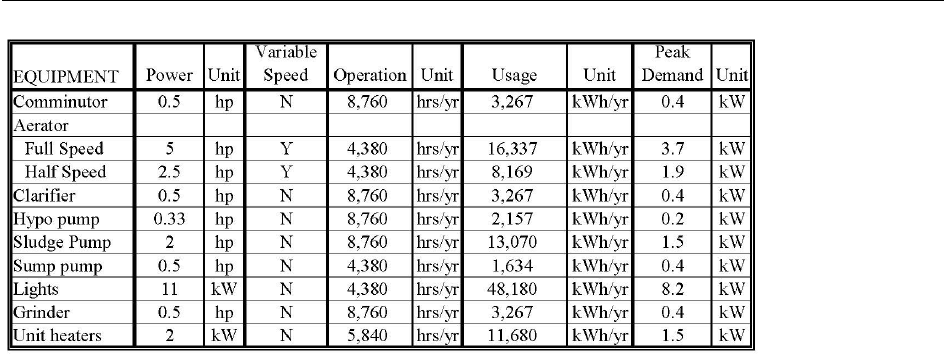
B-1
Appendix B. Example Spreadsheet Showing Baseline of
Energy Use

C-1
Appendix C. Economic Evaluation Methods
To determine whether an energy efficiency improvement project will be cost effective, most
municipalities consider the “Simple Payback” (SPB) or the “Life Cycle Cost” (LCC). Typically, for smaller
projects involving equipment replacement and/or low up-front capital costs, with low maintenance
costs, using the SPB method is appropriate. However, for larger projects involving significant up-front
capital costs, multiple cost factors and variations in annual cash flow, LCC analysis is preferred.
C.1 Simple Payback
The SPB method calculates the length of time over which cumulative energy savings and other project
benefits will be equal to (or “payback”) the initial project investment. To calculate the SPB, divide the
total project cost by the total expected benefit.
)/($_
($)__
)(
yrsavingsAnnual
projectofCost
yrSPB =
For example, assume that a facility is evaluating Project A: whether to replace their motors with more
efficient models. If the new motors cost $200,000 and are expected to reduce energy costs by $100,000
per year and last for five years before another $200,000 motor replacement is needed, then the SPB for
Project A is two years.
C.2 Life Cycle Cost
LCC analysis considers the initial cost of the project as well as all of the costs and benefits over the
lifetime of the project. The LCC approach incorporates the time value of money, the volatility of utility
costs and other factors such as operation and maintenance or other costs.
∑ ∑
∑ ∑
−+=
−=
−=
ngsAnnualSavisAnnualCosttCapitalCosprocessNewLCC
ngsAnnualSavisAnnualCostprocessCurrentLCC
where
processNewLCCprocessCurrentLCCLCCSavings
)_(
)_(
:
)_()_(
Fo
r example, assume the same facility is evaluating Project B: whether to use a new treatment process
which will cost $700,000 in the first year, with replacement costs of $200,000 every five years. Project B
is expected to save the facility $184,000 per year for 20 years. The SPB of this project is 3.8 years. On
first look, Project A is more appealing with a SPB of two years versus nearly four years for Project B.
However, Project B will generate more savings over time. Assuming an interest rate of 7% and an
escalation rate of 3%, the LCC of Project A saves $660,000 in today’s dollars whereas Project B saves
$1,300,000—a difference of $650,000.

C-2
Backup calculations for both examples are provided in the following pages.
Note: The examples provided are an oversimplification provided for the purpose of showing the payback
and life-cycle costs calculations. The examples do not take into consideration labor and parts costs over
the life of the project.
The U.S. Environmental Protection Agency (EPA) Energy Star Tools and Resources Library
(http://www.energystar.gov/index.cfm?c=tools_resources.bus_energy_management_tools_resources
)
provides links to various Financial Evaluation Tools including a Cash Flow Opportunity Calculator (a
Microsoft Excel-based tool) to help decision-makers to evaluate the benefits of installing energy
efficient equipment.
The US Department of Energy’s Federal Energy Management Program (FEMP) offers many resources to
assist with Life-Cycle Cost Analysis (https://www.energy.gov/eere/femp/federal-energy-management-
program) including FEMP’s Building Life-Cycle Cost Software, training opportunities and a Life-Cycle
Costing Manual.

C-3
LIFE CYCLE COST EXAMPLE - PROJECT A
Interest Rate =
i =
7.0%
Escalation Rate =
e =
3.0%
PROJECT A
Year
Capital
Replacement
Energy Savings
Total Annual
PW
(n)
Cost
Cost
(Annual)
Cost
Cost
0 $200,000 $200,000 $200,000
1
-$100,000 -$100,000 -$93,458
2
-$106,090 -$106,090 -$92,663
3
-$109,273 -$109,273 -$89,199
4
-$112,551 -$112,551 -$85,865
5
$231,855 -$115,927 $115,927 $82,655
6
-$119,405 -$119,405 -$79,565
7
-$122,987 -$122,987 -$76,590
8
-$126,677 -$126,677 -$73,727
9
-$130,477 -$130,477 -$70,971
10
$268,783 -$134,392 $134,392 $68,318
11
-$138,423 -$138,423 -$65,764
12
-$142,576 -$142,576 -$63,305
13
-$146,853 -$146,853 -$60,939
14
-$151,259 -$151,259 -$58,661
15
$311,593 -$155,797 $155,797 $56,468
16
-$160,471 -$160,471 -$54,357
17
-$165,285 -$165,285 -$52,325
18
-$170,243 -$170,243 -$50,369
19
-$175,351 -$175,351 -$48,486
20 $361,222 -$180,611 $180,611 $46,673
-$662,140
Future Annual Cost = Present Annual Cost x (1 + Escalation Rate)
Year
= A
o
(1+e)
n
(present annual costs).
Present Worth Cost = PW = Future Annual Cost / (1 + Interest Rate)
Year
= F / (1 + i)
n

C-4
LIFE CYCLE COST EXAMPLE - PROJECT B
Interest Rate =
i =
7.0%
Escalation Rate =
e =
3.0%
PROJECT B
Year
Capital
Replacement
Energy Savings
Total Annual
PW
(n)
Cost
Cost
(Annual)
Cost
Cost
0 $700,000 $700,000 $700,000
1
-$184,000 -$184,000 -$171,963
2
-$195,206 -$195,206 -$170,500
3
-$201,062 -$201,062 -$164,126
4
-$207,094 -$207,094 -$157,991
5
$231,855 -$213,306 $18,548 $13,225
6
-$219,706 -$219,706 -$146,399
7
-$226,297 -$226,297 -$140,926
8
-$233,086 -$233,086 -$135,658
9
-$240,078 -$240,078 -$130,587
10
$268,783 -$247,281 $21,503 $10,931
11
-$254,699 -$254,699 -$121,006
12
-$262,340 -$262,340 -$116,482
13
-$270,210 -$270,210 -$112,128
14
-$278,317 -$278,317 -$107,936
15
$311,593 -$286,666 $24,927 $9,035
16
-$295,266 -$295,266 -$100,017
17
-$304,124 -$304,124 -$96,278
18
-$313,248 -$313,248 -$92,679
19
-$322,645 -$322,645 -$89,214
20 $361,222 -$332,324 $28,898 $7,468
-$1,313,240
Future Annual Cost = Present Annual Cost x (1 + Escalation Rate)
Year
= A
o
(1+e)
n
(present annual costs).
Present Worth Cost = PW = Future Annual Cost / (1 + Interest Rate)
Year
= F / (1 + i)
n

State of New York
Andrew M. Cuomo, Governor
New York State Energy Research and Development Authority
Richard L. Kauman, Chair | Alicia Barton, President and CEO
COM-MFG-wwem-bk-1-v1
