
P1101331-003
Windows Driver
User Guide
ZC100/300 Series
Card Printer
i
Contents
Printing Preferences ......................................................................................................................................... 1
Setup Tab ............................................................................................................................................. 2
Status Bar ................................................................................................................................ 2
Printing ..................................................................................................................................... 3
Card ......................................................................................................................................... 4
Ribbon ..................................................................................................................................... 4
Encoding Tab ....................................................................................................................................... 7
Help & Support Tab .............................................................................................................................. 8
How-To Videos ........................................................................................................................ 8
Help & Support ........................................................................................................................ 8
Cleaning ................................................................................................................................... 8
Print Optimization and Adjustment ..................................................................................................... 10
Information ............................................................................................................................. 10
Color Panels .......................................................................................................................... 11
Black Extraction ......................................................................................................... 11
Adjustments ............................................................................................................... 14
Half Panel .................................................................................................................. 14
Proles ................................................................................................................................... 16
Black / Mono Panels .............................................................................................................. 16
Optimization............................................................................................................... 17
Adjustments ............................................................................................................... 18
Overlay/Specialty Panels ....................................................................................................... 18
YMCKLL ................................................................................................................................ 19
SDYMCKO ............................................................................................................................. 20
YMCKPO ............................................................................................................................... 21
Alignment ............................................................................................................................... 22
Help & Support ...................................................................................................................... 23
Advanced Settings ............................................................................................................................. 24
Information ............................................................................................................................. 24
Connectivity ........................................................................................................................... 25
Wired Connection ...................................................................................................... 25
Wireless Connection.................................................................................................. 26
ii
Conguring Wireless ................................................................................................. 27
Magnetic Encoding ................................................................................................................ 28
Settings...................................................................................................................... 28
Encode/Read Data .................................................................................................... 29
Conguration ......................................................................................................................... 29
Printer Settings .......................................................................................................... 30
Firmware and Settings............................................................................................... 31
Job Log ...................................................................................................................... 32
Security .................................................................................................................................. 32
Sensors and Calibration ........................................................................................................ 33
Sensors ..................................................................................................................... 33
Calibration ................................................................................................................. 34
Advanced Features ................................................................................................................ 34
Diagnostics ................................................................................................................ 35
Cong Request .......................................................................................................... 36
Help and Support ...................................................................................................... 37
Printer Properties ............................................................................................................................... 38
Sharing .................................................................................................................................. 38
Color Management ................................................................................................................ 38

1
Printing Preferences
Check the Zebra website for the latest version of this document.
The Printing Preferences control panel can be used to determine preferences such as which ribbon panels will
be used to print images on the card, where the card comes from (i.e., the input hopper or the manual feed slot),
and its destination. It is also used to make adjustments to colors and black panel quality; as well as printing test
cards, showing conguration information, and connecting to wired or wireless networks.
To open the Printing Preferences Control Panel:
y Windows 7 – Select Start, then click Devices and Printers. Right click the Zebra ZCXXX Card Printer,
and select Printing preferences from the pop-up menu.
y Windows 8 – Press Windows + I and select Control Panel from the pop-up menu. Select Hardware
and Sound, then select Devices and Printers. Right click the Zebra ZCXXX Card Printer, and select
Printing preferences from the pop-up menu.
y Windows 10 – Press Windows + I and select Devices, then select Printers and Scanners. Select the
Zebra ZCXXX Card Printer and click Manage, and then select Printing preferences.
The tabs listed below make up the menu structure of the Printing Preferences Control Panel:
y Setup
y Encoding
y Help & Support
The utilities listed below complete the menu structure:
y Print Optimization and Adjustment
y Advanced
At the bottom of the control panel window are the following buttons:
The Restore Defaults button sets the printing preferences back to factory settings.
The Cancel button closes the Printing Preferences Control Panel without applying the changes made.
The Apply button makes (or applies) the changes; the Printing Preferences Control panel remains open.

2
Setup Tab
The Setup tab enables the user to adjust selected card and print job parameters, and to print test cards.
Status Bar
The status bar shows the current state of the printer. When the status bar is green or yellow, you can still print.
A red status bar will inhibit printing until the error is corrected.
Status: Ready
Status: Ribbon Low
Status: Out of Cards 4001
The Setup window is divided into three sections:
y Printing
y Card
y Ribbon

3
Printing
The Orientation drop-down list tells the printer to print in either Landscape (horizontal) or in Portrait (vertical)
depending on the design or the desired use of the card. Note that the printing orientation cannot be mixed; in
other words, you cannot print portrait on the front and landscape on the back.
The Rotate 180° drop-down list tells the printer to rotate the image on the card 180° (degrees). Use this option if
you want the images to be oriented the same way depending on how the card is ipped over.
The following selections are available from the Rotate 180° drop-down list:
y None – does not rotate the image(s).
y Front – only rotates the image on the front of the card.
y Back – only rotates the image on the back of the card.
y Both – rotates the image on both the front and the back of the card.
The Print on both sides switch enables double-sided printing (applicable to dual-sided printers; ZC100 not
compatible).
The Copies selection species the number of cards to be printed. Click on the up or down arrow to increase or
decrease the number.
Print and Encode Same Side enables the user to encode a card and print an image on the mag stripe side.
This option is disabled when Print on Both Sides is enabled. To Print and Encode Same Side the printer must
be dual sided, Print on Both Sides must be set to No, and the printer must have a mag encoder.
Print Test Card enables the user to print one of two test card types:
The Graphics Test Card prints an image appropriate to the current ribbon
combination; and if Print on Both Sides is selected (for double-sided printers
only), a monochrome test image on the back.
The Conguration Test Card prints printer conguration information. If the
Wireless option is installed, and the printer is set to print single-sided, two cards
will be printed.

4
Card
The Source selection lets the user tell the printer where to take the card from. For example, if a single card
needs to be printed that is dierent from the cards in the input hopper, the user can select to manually feed a
single card to print on.
The following selections are available in the Card source drop-down list:
y Manual Feed Slot – only takes cards from the manual feed slot.
y Input Hopper – only takes cards from the input hopper.
y Auto Feed (default) – unless a card is fed in from the manual feed slot before the print job is sent, the
printer will take the card from the input hopper.
y Already in printer – for third-party applications that use this feature.
The Destination selection lets the user tell the printer where to send the nished cards. In some cases, it may
be necessary to send the nished card to the reject tray under secure conditions (if the printer lock is installed).
The following selections are available in the Destination drop-down list:
y Output hopper (default) – this sends the nished cards to the output hopper (located under the input
hopper).
y Reject bin – this option sends the nished cards to the reject bin which is accessible by opening the
print cover (applicable to dual-sided printers; ZC100 not compatible)
y Leave in printer – for third-party applications that use this feature.
Ribbon
Zebra card printers use ribbons (media) that come in two types: monochrome and color panels. Monochrome
ribbons are one continuous ribbon of a single color—typically black, but may be white, gold, or other single
color ribbons. With color panels, such as YMCKO (used for full color printing), each individual primary color
(yellow, magenta, cyan or YMC) along with black (K) and overlay or varnish (O) are laid out in sequence for one
complete card print process.
TAKE-UP
SPOOL
SUPPLY
SPOOL
Direction of Travel
1 Panel Set
Y M C K O
The printer will recognize the type of print ribbon installed and display it in the Type eld. The available ribbon
combinations will be shown in the Combinations drop-down menu. Additionally, the Print on both sides
and the Print and Encode on Same Side settings will aect the available ribbon combinations. The Images
Remaining status bar indicates how many images can still be printed on the installed ribbon. This feature
applies to ribbons with panels and refers to the panel set (YMCK); monochrome ribbons do not apply. When a
ribbon cartridge has 10 panel sets remaining, a Ribbon Low warning will be displayed.

5
The following table shows the supported ribbons and their respective combinations:
Ribbon Print on Both Sides
Print and Encode Same
Side
Ribbon Combination
YMCKO
O
O YMCKO front
On YMCKO back
On O
YMCO front / K back (default)
YMCKO front / YMCKO back
YMCKOK
O
O YMCKO front
On YMCKO back
On O
YMCKO front / K back (default)
YMCKO front / YMCKO back
1/2YMCKO
O
O YMCKO front
On YMCKO back
On O YMCKO front / YMCKO back
1/2YMCKOKO
O
O YMCKO front
On YMCKO back
On O
YMCKO front / KO back (default)
YMCKO front / YMCKO back
KrO
O
O KrO front
On KrO back
On O KrO front / KrO back
KdO
O
O KdO front
On KdO back
On O KdO front / KdO back
K (Monochrome)
Includes all single
color ribbons
O
O K front
On K back
On O K front / K back
YMCPKO
O
O YMCPKO front
On YMCPKO back
On O
YMCPO front / K back (default)
YMCPKO front / YMCPKO back
YMCKLL
O
O YMCKLL front
On YMCKLL back
On O
YMCLL front / K back (default)
YMCKLL front / YMCKLL back
SDYMCKO
O
O SDYMCKO front
On SDYMCKO back
On O
SDYMCO front / K back (default)
SDYMCKO front / SDYMCKO back
The YMC panels in a color ribbon are used to create the color image. The ZC100/300 Series printers use 24-bit
color data, color algorithms, and printhead management formulas to achieve 256 shades of color when printing
a full color image.
6
The printer uses the K panel to print black elements on a color image (see “Proles” on page 16), or barcodes
and text. This is a resin panel, which means it cannot be used to print continuous tones of color. The K panel
can only print binary (pure on or o) images.
K is also used to denote monochrome ribbons, which are available in black, white, gold, silver, red, and blue.
Monochrome ribbons are also made of resin materials, which means they cannot be used to print continuous
tones of color, and can only print binary (pure on or o) images.
Kd denotes a black dye panel, which allows continuous shades of gray to be printed, and is ideally suited for
photos and graphics.
The O panel is an overlay which protects the dye panels against fading due to the eects of UV light and
abrasion. Overlay can also be applied to K resin to further protect text and barcodes against abrasion. This
makes the KrO ribbon useful in applications where card is swiped against a magnetic stripe reader and text or
barcodes are printed on the opposite side of the magnetic stripe.
The L panels in the YMCKLL ribbon enable long lasting color personalization of cards without the use of
lamination. The combination of two extra thick overlay panels adds four times more abrasion resistance to a
color card, compared to a standard YMCKO ribbon. The panels can also be used to print security features,
which will appear as a watermark on the card, and uoresce under UV light. Refer to “YMCKLL” on page 19
for more information.
The S (silver) panel in the SDYMCKO ribbon enables 3D-like visual eects to be created on the card. The Sr is
a silver resin panel and it can be printed on the entire card for a metallic eect, or underneath a specic graphic
element, like a logo or text and then printer over with YMC to create a unique visual eect. Refer to “SDYMCKO”
on page 20 for printing options.
The P (pearlescent) panel is a color shifting panel in the YMCPKO ribbon, enabling covert security elements to
the printed on the card, on demand. Images printed using the K and the P panels should ideally not overlap in
the design of the card. Refer to “YMCPKO” on page 21 for more printing options.

7
Encoding Tab
The Encoding tab displays the primary magnetic encoding settings, and is only accessible if the magnetic
encoding option is installed. To change these settings, or to further customize the magnetic encoding settings,
click on Advanced Settings.
Encoding – When set to On, a card with a magnetic stripe will be encoded when a print job with magnetic
encoding data is sent to the printer. When set to O, the printer will not encode any cards.
Encode Only – When set to On, only the encoding portion of a print job will be completed. When set to O, both
encoding and printing will be completed.
Verication – When set to On, the printer will verify the data that has been encoded to the card. When set to
O, the printer will not verify the data that has been encoded to the card.
Type – ISO is the standard type of magnetic encoding for most cards. Other formats may be set in Advanced
Settings.
Coercivity – The amount of energy required to encode the card. Cards with a magnetic stripe require either high
coercivity or low coercivity.
Hex – The format for the data being encoded to the card. When set to On, the data being encoded to the card
will be in hexadecimal format. When set to O, the data will be in standard ANSI format.
Erase Before Encode – Erases all data on the magnetic stripe before encoding new data.

8
Help & Support Tab
The Help & Support tab oers users several options to help with the printer, as well as the ability to initiate
cleaning.
How-To Videos
The How-To-Videos section oers users videos explaining common tasks and troubleshooting solutions.
Help & Support
The Help & Support section oers users links to the dierent sections of the Product Support page.
Click on Product Manuals link to download user documentation for your printer.
Click on Driver Support to download driver and rmware updates, and other software for your printer.
Click on Knowledge Base to look up specic issues with your printer.
Click on the Technical Support link to contact a representative to assist you with your printer.
Click on Request a Repair if you need expert assistance with a printer issue.
Cleaning
Caution • PROTECT YOUR FACTORY WARRANTY!
The recommended cleaning procedures must be performed to maintain your factory warranty.
NEVER loosen, tighten, adjust, bend, etc., any part or cable inside the printer.
NEVER use a high pressure air compressor to remove particles in the printer.

9
The regular use of cleaning cards will clean and maintain important parts of your printer that cannot be reached,
including the printhead, the transport rollers, and the magnetic encoder station (optional).
The Cleaning section shows the user how many cards can be printed before the next cleaning is required. Click
to initiate the cleaning process; follow the on-screen instructions.
Step 1. At the prompt, remove the ribbon and cards from the printer.
Step 2. At the prompt, insert the cleaning card into the manual feed slot on the printer.
Step 3. The cleaning process will begin.
Step 4. When the cleaning process has nished, remove the used cleaning card after it has been
ejected.
Step 5. Replace the ribbon and cards.

10
Print Optimization and Adjustment
The Print Optimization and Adjustment utility allows the user to optimize and adjust the printer settings when
the default settings do not achieve the desired image quality. Additionally, most settings are shown in a preview
window to demonstrate how the settings will aect the card image.
The window options are arranged in tabs as follows:
y Information
y Color Panels
y Proles
y Black/Mono Panels
y Overlay/Specialty Panels
y Alignment
y Help & Support
Note • The Color Panels, Black/Mono Panels, and Overlay/Specialty Panels tabs are only available
when ribbon is installed that has those panels. For example, Black Mono ribbon does not have Color
Panels or Overlay/Specialty Panels, so those tabs would not be available.
Information
The Information tab displays the current state of the printer (i.e., Ready, Input hopper open, etc.), the Type of
ribbon installed (i.e., YMCKO), the ribbon combination currently selected (i.e., YMCKO front), and the current
settings for the Black Panel (i.e., Enabled/Disabled/Not Applicable), Black Panel Extraction (Enabled/Disabled/
Not Applicable), and Overlay/Specialty Panel (Enabled/Disabled/Not Applicable).
In the card Preview window, you can switch between dierent sample cards, or you can load your own image.
Click on the drop-down list to select the card image to preview, or click
(File Browser), locate the le you
wish to upload, and click Open. Currently, only BMP images are supported.

11
Color Panels
The Color Panels tab contains settings for:
y Black Extraction
y Adjustments
y Half Panel (shown when half-panel ribbon is loaded)
Black Extraction
Note • The black extraction option is only available with color ribbons, when YMC and K panels are on
the same side (i.e., YMCKO front).

12
Black extraction is the process by which the driver examines the color image being used for the print job and
divides it up into black elements and color elements. Black elements by default are any pixels that have an RGB
code value of (0,0,0). This threshold can be expanded up to (25,25,25) using the Black Extraction Threshold
slider.
When black extraction is turned on, the printer uses the K panel to print black elements, rather than using the
YMC panels. A preview of the image content that has been identied as black is shown in the Preview pane on
the Black Extraction page.
By default, when black extraction is enabled it is applied to the entire card. However, when black extraction is
applied to image content (such as portraits or scenic pictures), the user may nd that the printed image looks
unnatural. In this case, the user can select to apply black extraction to only a portion of the card by using the
Locations to Extract option. For example, the user may select to “undene” an area that corresponds to the
location of the content that they don’t want black extraction applied to.
In the preview, the area to be extracted is highlighted in blue, while the area that should not be extracted is
clear.
The discussion above considers the use case of color images; however, some applications, such as Card
Studio, allow the user to specically identify which elements of the image should be printed with the K panel.
These elements fall into three categories: text, graphics, and bitmaps. In order for the driver to properly handle
this request, these elements need to be checked in the Elements to Extract section.
By default, all of these elements are checked. If any of these elements are unchecked, then the driver will not
apply black extraction to these elements, regardless of whether the elements are identied by the application to
be printed with the K panel.
Lastly, it is sometimes the case that text in an image is anti-aliased, meaning that the central pixels are black
while the outer pixels are near-black. While anti-aliasing can make text look smoother, it may look unnatural
when the inside of the text is printed with K panel and the outside of the text is printed with YMC panels. To
improve this situation, the user may choose to enable the Print Black data with Composite (YMC and K) option.
13
When this feature is enabled, the black elements of the image are printed with both YMC panels and K panels.
This makes for a smoother transition between black and near-black content. While this option may work well for
text or other anti-aliased content, it is not recommended for use with barcodes, as they are not anti-aliased and
any misregistration between the YMC and K panels will degrade the scannability of the barcode.
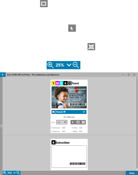
Using the Area Manager
The Extraction Area tools enable the user to selectively dene an are to which black extraction is applied. These
tools are only available when Locations to Extract is set to Dened Areas or Undened Areas.
Dened areas applies black extraction to areas of the image inside of the zones specied in the Area manager,
Undened areas applies black extraction to areas of the image outside of the zones specied in the Area
manager.
To create a zone, select the rectangle icon , click an area of the image to establish the rst corner of the
zone, drag the cursor until the zone is the desired size and shape, then release the mouse button. Note that
multiple zones can be dened.
To select, move, or resize a zone, select the arrow icon
, click a zone to select it, then drag it to move it, or
drag on the edges to resize it.
To delete a zone, select the rectangle icon with an “X” through it
, then click the zone that you want to delete.
If larger preview image is needed to work with, click on the preview utility (<). This enables the use of the full
window to create the extraction area. Click on
(zoom tools) to enlarge the image.

14
Adjustments
The Intensity adjustments gives the user control over how much of each color is applied to the card. For
example: If the user feels that more yellow should be applied, the Y slider can be adjusted higher, this applies
to the M and C sliders also. Additionally, the sliders can be adjusted simultaneously by clicking the
(Link)
button.
Brightness adjustment boosts or reduces the mid-tones in an image, which makes an image appear brighter or
darker.
Contrast refers to the range of tonal values in an image. High contrast increases the range of light to dark, while
low contrast reduces the range.
The Preheat controls the preheating of the printhead. During printing, the individual pixels go from a “rest”
temperature to “printing” temperature very quickly, however for thin lines the pixels may not be able to reach
the activation temperature of the ribbon before returning back to the rest temperature. Increasing the preheat
may make it easier for the pixels to reach the activation temperature, resulting in a darker or more complete line
being printed.
The Sharpness adjustment changes the visual perception of the clarity and resolution of an image.
y None – does not apply any sharpening to the image.
y Low – applies some sharpening to the image.
y Normal – (default) apples a degree of sharpening that, while noticeable, is not unsightly.
y High – applies a degree of sharpening that is noticeable and may seem unsightly. This can also be a
purposeful eect.
Half Panel
The Half Panel ribbons are used for printing full color images on a smaller area of a card (i.e., an ID photo).
The color panels are half the size of a normal color panel so waste is reduced and cards printed per ribbon is
greater; the K (black) and Overlay panels remain full size.
Note • The half panel option is only available when a half panel ribbon is installed in the printer.

15
Note • The printable area for the color portion of the half-panel ribbon is 34 millimeters wide.
Y M C K O
Y M C K O
Typical YMCKO Ribbon
Half Panel YMCKO Ribbon
The Print Settings and Adjustments remain the same, with the exception of the Half Panel Options.
The Half Panel Oset has four settings:
y Auto (default) – detects the location of the color portion of the image and starts color printing at that
location. In some cases, Auto detect may not be suitable for your image. In such cases, the other three
options may work better.
The Color Threshold slider is used to adjust the sensitivity of the algorithm that determines the starting
location of the color panels. It is only available with the Auto oset.
y Custom – enables a manual oset setting.
The Oset Value slider is only available with the Custom oset.
Note • Measurements are in pixels and start at the left, 1 pixel = 0.085 mm.
y Left Side – sets the print area to the left side of the card.
y Right Side – sets the print area to the right side of the card.

16
Proles
The Proles page is used to load a dierent prole to the printer. The prole is used to control many functions
of the printer, such as print tensions, amount of energy used for dierent panels, etc.
The only lename currently allowed for the prole is StdPrnProle.json. However, each prole has a version
number that can be read after it has been loaded to the printer. Note that after loading the prole to the printer,
the user must navigate away from the page and then back to the Proles page to see the new version number.
To load a new prole, click
(File Browser), select the desired StdPrnProle.json le, and click Open. Click
the Update button, then click OK to acknowledge that the printer will be restarted to complete the prole update.
Black / Mono Panels
The Black/Mono Panels tab displays available options to optimize black panel printing for the type of image
being printed.
The available options for the Front and Back are the same and can be set independently.

17
Tip • The selection that most closely matches the type of image you are trying to optimize for may not
be the best selection. If the selection does not produce the desired results, experiment with the other
selections.
Optimization
Optimization enables presets for optimal printing:
y Mixed will optimize black panel printing for both text and barcodes, or text and pictures, or other
combinations.
y Barcode optimizes black panel printing for sharp barcodes that are easily read by scanners.
y Text optimizes black panel printing to produce crisp, clear text.
Monochrome Conversion is used to convert continuous tone 8-bit-per-pixel RGB or gray image content into
binary1-bit-per-pixel content, as monochrome panels can only print binary (pure on or o) images.
Threshold – This is the simplest method for converting from 8 bits per pixel to 1 bit per
pixel. For example, the input pixel can be a value from 0 to 255. If the threshold is 128,
any pixel from 0 to 128 becomes full on (1); and any pixel that is higher than 128 becomes
full o (0). This mode works best for text, barcodes, line art, logos -- everything except
continuous-tone pictures. Use the Threshold slider to set the desired value.
Diusion – Dither diusion is used primarily where you have a full color (RGB image with
8 bits per pixel) or full gray (single color but still 8 bits per pixel) that you need to print with
binary printing (can only print full-on or full-o; i.e., 1 bit per pixel). Typically preferred over
halftoning for most images. Use the brightness and contrast sliders to adjust the levels to
the desired output.
Halftone – prints the bitmap image as a 6 x 6 halftone image, which simulates continuous
tone imagery through the use of dots, varying either in size or in spacing.

18
Adjustments
The Intensity adjustments gives the user control over how dark or light the black/mono panel is printed.
Brightness adjustment boosts or reduces the mid-tones in an image, which makes an image appear brighter or
darker.
Contrast refers to the range of tonal values in an image. High contrast increases the range of light to dark, while
low contrast reduces the range.
The Preheat controls the preheating of the printhead. During printing, the individual pixels go from a “rest”
temperature to “printing” temperature very quickly, however for thin lines the pixels may not be able to reach
the activation temperature of the ribbon before returning back to the rest temperature. Increasing the preheat
may make it easier for the pixels to reach the activation temperature, resulting in a darker or more complete line
being printed.
Overlay/Specialty Panels
The Overlay/Specialty Panels tab oers the user adjustments to the overlay panel; and, if equipped, adjustments
to the specialty panel (such as the L or Silver panel).

19
Print Overlay Panel On/O determines if the panel is used. If the selections is set to On, the overlay panel
is used and the remaining options are available; if the selection is set to O, printing of the overlay panel is
skipped.
Bitmap On/O tells the printer to print a solid image using the Overlay panel, such as a logo, a shape, or text
that has been converted to a 1-bit per pixel bitmap. Set Bitmap to O if no image is to be used. If Bitmap is set
to On, click
(File Browser), locate the le you wish to upload, and click Open. Only 1-bit BMP and JPG les
are supported.
Rotate 180° is enabled when Bitmap is set to On, or when Bitmap is set to O and the Location is set to any
selection other than Full Card
Invert is enabled when Bitmap is set to On, and reverses the dark and light colors--creating a negative image.
The Location option enables the user to dene areas of the card for which to apply the overlay. The choices are:
y Full card applies the overlay to the entire printed area.
y Dened Areas – applies the overlay to areas of the image inside of the zones specied in the Area
manager (see “Using the Area Manager” on page 13).
y UnDened Areas – applies black extraction to areas of the image outside of the zones specied in the
Area manager (see “Using the Area Manager” on page 13).
y Smartcard – This option leaves a small area open over a smart card chip.
y Magnetic Stripe – This option leaves an area open over the magnetic stripe.
The Intensity adjustments gives the user control over how dark or light the overlay panel is printed.
YMCKLL
The options for the L panel are the same as for the Overlay panel. When both L panels are printed on the same
side of the card, and the bitmap option is enabled, the bitmap is only printed using one of the L panels. This
allows security features to be printed while maintaining a protective overlay.

20
SDYMCKO
There are three option combinations for printing with the Silver (S) panel:
1. Print Silver Panel: On
Full Card: O
Bitmap: O
This combination enables the user to print a unique silver panel image for each card.
This combination requires the user to send two images to the printer in order to print with the silver
panel. The rst image is for the silver panel, while the second image is for the color panels. If K is also
on the same side (i.e., SDYMCKO front), then K will be extracted from the second image if this feature is
enabled. If K is on the back side of the card (i.e., SDYMCO front / K back), then a third image is needed
for the K panel—the rst image is still for the silver panel and the second image is still for the color
panels. When printing SDYMCKO front / SDYMCKO back, four images need to be sent to the printer.
The rst image is for the silver panel on the front, the second image is for the color and K panels on
the front, the third image is for the silver panel on the back, and the fourth image is for the color and K
panels on the back.
2. Print Silver Panel: On
Full Card: On
Bitmap: O
This combination enables the user to give the entire card a shiny look. Note that non-printed areas will
appear silver, so this combination is best suited for color images that completely cover the entire card.
This combination lls the entire card with the silver panel. The user only needs to send one color
image to the printer for single sided cards (i.e., SDYMCKO front), or two images to the printer for dual-
sided jobs (i.e., SDYMCO front / K back (rst image color, second image mono) or SDYMCKO front /
SDYMCKO back (both images color)).
3. Print Silver Panel: On
Full Card: O
Bitmap: On
This combination enables the user to print the same image with the silver panel for every card, such as
for a logo or graphic.

21
This combination uses the same user-supplied bitmap for the silver panel for every card. Once the
bitmap has been selected, the user only needs to send one color image to the printer for single sided
cards (i.e., SDYMCKO front), or two images to the printer for dual sided jobs (i.e., SDYMCO front / K
back (rst image color, second image mono) or SDYMCKO front / SDYMCKO back (both images color)).
Note that the front and back silver panel options can be set independently; however, this only applies to
the SDYMCKO front / SDYMCKO back ribbon combination. The number and type of images required for
each side are as specied above for single-sided cards.
4. Print Silver Panel: O
Silver panel is not printed.
Lastly, the Intensity slider can be used to increase or decrease the intensity of the silver panel. In most cases
this should not be necessary; however, some card types may require more or less energy to print successfully
with the silver panel.
YMCPKO
There are two option combinations for printing the Pearlescent (P) panel.
1. Print Pearlescent Panel: On
Bitmap: O
This combination enables the user to print a unique pearlescent panel image for each card.
This combination requires the user to send two images to the printer in order to print with the pearlescent
panel. The rst image is for the color panels, and the second image is for the pearlescent panel. If K is
also on the same side (i.e., YMCPKO front), then K will be extracted from the rst image if this feature
is enabled. If K is on the back side of the card (i.e., YMCPO front / K back), then a third image needs to
be sent to the printer for the K panel. The rst image is still for the color panels and the second image
is still for the pearlescent panel. When printing YMCPKO front / YMCPKO back, four images need to be
sent to the printer. The rst image is for the color and K panels on the front, the second image is for the
pearlescent on the front, the third image is for the color and K panels on the back, and the fourth image
is for the pearlescent panel on the back.
2. Print Pearlescent Panel: On
Bitmap: On

22
This combination enables the user to print the same image with the pearlescent panel for every card,
such as a logo or graphic.
This combination uses the same user-supplied bitmap for the pearlescent panel for every card. Once the
bitmap has been selected, the user only needs to send one color image to the printer for single sided
cards (i.e., YMCPKO front), or two images to the printer for dual sided jobs (i.e., YMCPO front / K back
(rst image color, second image mono) or YMCPKO front / YMCPKO back (both images color)).
When the Bitmap option is used, the user has the added exibility to rotate the bitmap and/or to invert
the bitmap. The rotate option rotates the image 180 degrees. The invert option turns all active (black)
content inactive (white), and vice versa. These options can be used independently or together.
Note that the front and back pearlescent panel options can be set independently; however, this only
applies to the YMCPKO front / YMCPKO back ribbon combination. The number and type of images
required for each side are as specied above for single sided cards.
3. Print Pearlescent Panel: O
Pearlescent panel is not printed.
Lastly, the Intensity slider can be used to increase or decrease the intensity of the pearlescent panel. In most
cases this should not be necessary, however some card types may require more or less energy to print on
successfully with the pearlescent panel.
Alignment
The Alignment tab enables the user to make corrections to printing if the image is o center, or the panels are
misaligned with each other.
X Oset adjusts the placement of the image along the long axis.
Y Oset adjusts the placement of the image along the short axis.
Image Fill changes the length of the printed image.
Image Trim - Mono changes the length of the printed image when monochrome ribbon is used.
Image Trim - K Panel changes the length of the part of the image printed with the K panel.
X Oset Specialty Panel adjusts the placement of the specialty panel image along the long axis.
Image Trim - Specialty Panel changes the length of the part of the image printed with the specialty panel.


24
Advanced Settings
The Advanced Settings window is a separate utility that enables adjustments and conguration of the printer.
The window options are contained in the following tabs:
y Information
y Connectivity
y Magnetic Encoding
y Conguration
y Security
y Sensors and Calibration
y Advanced Features
y Help & Support
Information
The Information tab shows the current state of the printer, the current version of the driver, the serial number of
the printer, the current installed rmware version, the interface type, and the total number of cards printed.
The Ribbon section of the Information tab show the current ribbon type installed in the printer, the selected
panel combination, and the number of images remaining on the current ribbon cartridge.
The Options section of the Information tab shows the available options and their respective installed status.

25
Connectivity
The Connectivity tab enables the user to congure the respective network options, either wired (Ethernet) or
wireless (Wi-Fi).
Wired Connection
Note • Wired connection settings are congured while the printer is connected via USB; this is to
prevent loss of communication.
Status
The status section of the Wired Network window shows either Not Connected or Connected, the IP address of
the printer, and the MAC address.
Settings
Turn DHCP o to set a static IP address.
Turn SNMP o if you do not want the printer to be discoverable on the network.
DNS Server Address: Displays the address of the Domain Name Server that the printer connects to.
Printer DNS Name: Displays the name of the printer as it appears in the Domain Name Server.
IPv4 Address: Displays the IP address of the printer (if connected).
Subnet Address: Displays the subnet the printer resides on.
Gateway: Displays the gateway.
Note • DNS Server, IPv4, subnet, and gateway settings are congurable only when DHCP is turned o.

26
Wireless Connection
Note • Wireless connection settings are congured while the printer is connected via USB or Ethernet;
this is to prevent loss of communication.
Important • The wireless option must be installed in the printer to use this feature. Contact you Zebra
representative to verify the wireless option is installed.
Status
The status section of the Wireless Network window shows Not Connected, Scanning, or Connected. It also
displays the SSID the printer is connected to, channel, the IP address of the printer, the MAC address, security
type, and signal strength.
Settings
Wireless Radio On/O: Turns the wireless connection on or o.
Wireless Band Preference: This selection applies only if the same SSID is broadcasting in 2.4 and 5GHz. If
None is selected, the printer will choose the best signal strength.
Turn DHCP o to set a static IP address.
Turn SNMP o if you do not want the printer to be discoverable on the network.
DNS Server Address: Displays the address of the Domain Name Server that the printer connects to.
Printer DNS Name: Displays the name of the printer as it appears in the Domain Name Server.
SSID: Displays the name of the wireless network the printer is connecting to.
IPv4 Address: Displays the IP address of the printer (if connected).
Subnet Address: Displays the subnet the printer resides on.
Gateway: Displays the gateway.
Note • DNS Server, IPv4, subnet, and gateway settings are congurable only when DHCP is turned o.

27
Conguring Wireless
Step 1. From the Settings section of the Wireless sub-tab, turn Wireless radio On.
Step 2. Set the wireless band preference as well as the DHCP and SNMP settings.
Step 3. From the SSID drop-down menu, select the wireless network to connect to. If this is the rst time
connecting, or if the wireless network does not appear in the drop-down list, click on the Add
button to create a new wireless network connection.
Step 4. In the SSID eld, enter the name of the wireless network.
Step 5. From the Security drop-down list, select the type of security that is in eect for the wireless
network.
Step 6. In the Password eld, enter the password if applicable and for WPA-PSK; or if the security type
is WPA-EAP, enter the EAP elds.
Step 7. Click Apply.
Step 8. From the Wireless conguration window, click Apply.
The printer will attempt to connect to the network. If successful, the status section of the wireless conguration
window will show Connected and the printer IP address will be shown. Use this IP address for the following
steps.
Step 9. Run the Windows Driver Installer and choose Modify.
Step 10. Select Install Ethernet printer drivers. If your printer is on the same subnet as your PC, the
printer will show in the list of printers. If the printer is not on the same subnet as your PC, enter
the IP address returned by the printer after Step 7.
Step 11. Continue the installation process.
When the installation process has nished, your printer will be set up for printing. If the printer resides on the
same subnet as your PC, Windows will show the printer by its full model name (e.g., ZC300 Network Printer), if
the printer does not reside on the same subnet as your PC, windows will return a generic model name (e.g., ZC
Network Printer).

28
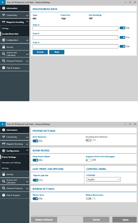
Magnetic Encoding
The Magnetic Encoding tab enables the user to congure settings for magnetic encoding, and to encode and
read cards equipped with a magnetic stripe.
Settings
Switch Magnetic Encoding to On to enable magnetic encoding.
Switch Encode Only to On to bypass any printing to the card.
Switch Verication to On (default) to enable the printer to verify the encoding process was successful.
Switch Erase Before Encode to On to erase the magnetic stripe before encoding.
Select the Type of encoding to perform:
y ISO – standard format for magnetic encoding.
y AAMVA – American Association of Motor Vehicle Administrators (AAMVA). AAMVA modifes the ISO
standard by allowing 79 alphanumeric data characters on track 1 (plus SS, ES, and LRC), 37 numeric
data characters on track 2 (plus SS, ES, and LRC), and 79 alphanumeric data characters on track
3 (plus SS, ES, and LRC). Bit density is the same as ISO, however track 3 has 7 bits per character
(because it is alphanumeric).
y BINARY – When BINARY is selected, the user can modify the Bit Density on each track. The ISO format
species a bit density of 210 bpi for tracks 1 and 3 and 75 bpi for track 2. With BINARY selected, the
user can choose between 75 bpi or 210 bpi for each track.
y CUSTOM – When CUSTOM is selected, the user can not only modify the bit density on each track, but
they can also modify the character size (between 3 and 7 bits per character) and the LRC Parity (ISO
standard is Odd, CUSTOM also allows Even).
BINARY and CUSTOM are custom modications to the ISO format. Cards encoded with BINARY or CUSTOM
formats typically will not work in standard magnetic stripe readers, and should therefore be reserved for specic
applications.
Switch Hex Encoding to On to use hexadecimal format for encoded data.
Track 1 allows up to 76 alphanumeric data characters (plus start sentinel, end sentinel, and longitudinal
redundancy check (LRC) character). Bit density is 210 bpi (bits per inch) and there are 7 bits per character
(derived from ASCII). Bit density is how tightly the data bits (1’s and 0’s) are spaced together on the magnetic
stripe.
29
Track 2 allows up to 34 numeric data characters (plus SS, ES, and LRC). Bit density is 75 bpi and there are 5
bits per character.
Track 3 allows up to 104 numeric data characters (plus SS, ES, and LRC). Bit density is 210 bpi and there are 5
bits per character.
Encode/Read Data
The Encode/Read Data section is used to verify the performance of the magnetic encoder.
Conguration
The Conguration tab is divided into three sub-tabs:
y Printer Settings
y Firmware and Settings
y Job Log

30
Printer Settings
The Printer Settings sub-tab is divided into ve sections:
In the Printer Settings section, the user can turn Error Recovery on or o and Encoding over Ethernet on or o.
In the Kiosk Modes section, the user can enable Kiosk Power Mode, and enable Suppress Driver Error
Messages. With Kiosk Power mode set to On, the printer will power up as soon as power is applied; with Kiosk
Power Mode set to O (default), the user must press the power button at the front of the printer to power up the
printer.
The Last Print Job Options section is where the user can choose to reprint the last job from the Operator
Control Panel (OCP).
In the Control Panel section, the user can change the language of the control panel. The available choices are
English, French, Italian, Spanish, Portuguese, German, Polish, Russian, Chinese, and Arabic.
In the Ribbon Settings section, the user can turn Ribbon Sync on or o. With Ribbon Sync turned o, when
the top cover is opened and then closed, or the printer is turned o and on, the ribbon will not advance as
long as the ribbon has not been removed. The user can also turn Ribbon Decrement on or o. With Ribbon
Decrement turned o, the ribbon is prevented from decrementing during printer initialization. It is recommended
that Ribbon Decrement not be used during normal operation.

31
Firmware and Settings
The Firmware and Settings sub-tab is divided into two sections:
In the Firmware section, the user is shown the current rmware version, and can update to the latest rmware.
Click
(File Browser), locate the le you wish to upload, and click Open. Then click .
A dialog box with several cautionary statements will be displayed, conrm you understand the risk by clicking
OK.
The rmware is sent to the printer. The printer status will be displayed in the status banner at the top of the
Setup tab; or, if equipped, the printer LCD screen. Click OK.
A progress bar is shows the status of the rmware update.
WARNING • Do not turn o printer power during rmware upgrade or serious damage to the printer
may occur. The printer will automatically reboot at the end of the upgrade process.
In the Save/Restore Settings section, the user can save or restore previously saved settings for the Printer and
The Driver.

32
Job Log
The Job Log sub-tab is divided into two sections:
The Job Log section is where the user can turn the job log on or o. With Job Log turned on, select a location
to store the Job Log by clicking
(File Browser), locate the folder you wish to store the log in and click OK.
Enable Create New Log File Each Day to create a new log le each day; when enabled, the user can create a
unique le name and a separator to dierentiate each day’s log. Click
to clear all logs from the local
computer or network.
With Job Log turned on, the user can select what information gets stored in the log under the Log Contents
subsection.
Security
The Security tab is divided into two sections:
In the Security Settings section, the user can set Erase Job Data After Sending On or O. This will prevent the
last print job from being recovered.
In the Printer Passkey sections, the user can enable the following options:

33
Setting Printer Passkey to On will enable the user to set a master passkey to be able to access the control
panel features.
Important • The Printer Passkey is not recoverable. Make sure when setting a printer passkey that is
remembered or written down in a secure location.
Setting Host Authentication to On enables the printer to verify that the computer sending the print job is
authorized to do so.
Setting Data Encryption to On will encrypt the data being sent to the printer so that if it’s intercepted it will not
be readable.
Sensors and Calibration
The Sensors and Calibration tab is divided into two sub-tabs:
y Sensors
y Calibration
Sensors
The Sensors sub-tab is divided into three sections:
The Feeder section tracks the sensors in the feeder section of the printer and noties the user of the current
status.
The Engine section tracks the sensors in the main section of the printer and noties the user of the current
status.
The Options section tracks the sensors in the installed options of the printer and noties the user of the current
status.

34
Calibration
The Calibration sub-tab is divided into three sections:
The Printhead section tracks the serial number and resistance value of the currently installed printhead. Use
this section when installing a new printhead to enter new values.
The Smartcard Osets sections identies values for dierent smartcard types, and enables the user to change
the values.
The Calibration section enables the user to calibrate certain sensors in the printer. This option can be used if a
particular sensor is suspected to not be working properly. Currently, the only sensor available to calibrate is the
Ribbon Detect Sensor.
Advanced Features
Important • The Advanced Features tab is password protected and should only be accessed by
trained personnel.
When prompted, enter the password to access the Advanced Features.
35
The Advanced Features tab is divided into two sub-tabs:
y Diagnostics
y Cong Request
Diagnostics
The Diagnostics sub-tab window is divided into seven sections:
y Motor
y Cam
y Transport
y Sensor
y Rotate
y Panel
y Fan
The Motor section enables the user to activate the motors individually. Select the motor, the motor speed
(if applicable), and direction from the drop-down lists and click
. The motor will engage at the selected
settings, click
to disengage the motor.
WARNING • Do not engage the card feed motor with cards present in the input hopper or serious
damage may result.
Note • Each motor can be engaged in either Forward or Reverse.
The Card Feed motor can be engaged at speeds ranging from 0–2000 in increments of 100.
y The Card X motor can be engaged at speeds of 1–20 in increments of 1.
y The Ribbon motor can be engaged at a single speed only.
y The Head Lift motor can be engaged at speeds of 0–2000 in increments of 100.
y The Options motor can be engaged at speeds of 0–2000 in increments of 100.
y The Flipper motor can be engaged at speeds of 0–2000 in increments of 100.
The Cam section is used to drive the lift cam for either the options module (if installed), or the printhead to be
put into preset positions.
y The Options module can be set to Contact, Mag, or Home.
y The Printhead can be set to position A–E.
The Transport section sends cards to dierent locations in the printer.
y Feeder to Card Sync
y Card Sync to Options
y Engine to Flipper Hold
y Engine to Flipper Flip
y Engine to Flipper Eject
y Engine to Flipper Reject

36
y Flipper to Reject
y Flipper to Engine
y Options to Card Sync
y Engine to Exit
The Sensor section enables the user to turn dierent sensors on or o.
y Card Out
y Lid
y Printer Lock
y Card Feed
The Rotate section is used to move the ipper (if installed) to dierent positions.
y Accept
y Eject
y Reject
y Flipper Init
y Flipper Rotate to Home
The Panel section is used to move the specied ribbon panel into the ready position. The drop-down menu
contents will vary depending on the ribbon installed.
The Fan section turns the cooling fan(s) on or o. Currently, only the printhead fan is supported.
Cong Request
The Cong Request section is divided into two sections:
The Command Request section is used to generate a secure request to change certain parameters of the
printer. The user then sends this request to Zebra Technical Support.
Important • The request generated is specic to the printer and cannot be used on other printers.
The Response section is used to load the Zebra generated response for that specic printer.

37
Help and Support
See “Help & Support Tab” on page 8.
The Cleaning section in the Help and Support tab of the Advanced Settings utility has several additional setting
to congure printer cleaning:
The Clean Printer Error Mode setting tells the printer to either Stop Printing when the cleaning notication
occurs, or to Allow Printing (default). If the user sets the error mode to Stop Printing, cleaning must be done
before any printing can continue. If the user sets the error mode to Allow Printing, printing can continue and
cleaning can be done at a later time.
The Cleaning Interval determines how many cards can be printed before cleaning is required; the
recommended (and default) value is 1,000 cards, and the maximum cleaning interval is 5,000 cards.
Important • Zebra does not recommend continued printing past the default cleaning interval as dust
and debris will collect on the print surfaces and result in poor print quality.
The Pre-Cleaning Count displays a warning in the driver control panel and the printer display (ZC100 not
applicable) showing the number of cards remaining before cleaning is due. The default value is twenty (20).

www.zebra.com
Printer Properties
To open the Printing Preferences Control Panel:
y Windows 7 – Select Start, then click Devices and Printers. Right click the Zebra ZCXXX Card Printer, and select
Printer properties from the pop-up menu.
y Windows 8 – Press Windows + I and select Control Panel from the pop-up menu. Select Hardware and Sound,
then select Devices and Printers. Right click the Zebra ZCXXX Card Printer, and select Printer properties from
the pop-up menu.
y Windows 10 – Press Windows + I and select Devices, then select Printers and Scanners. Select the Zebra
ZCXXX Card Printer and click Manage, and then select Printer Properties.
Sharing
On the Sharing tab (Sharing Property Page), you can choose to share the printer over the network and install additional
drivers to accommodate dierent operating systems.
To share a printer, select Share this printer; and specify a name in the Share name eld for the shared resource.
To change the shared name, simply enter a new name in the Share name eld.
To quit sharing a printer, deselect Share this printer.
Render print job on client side check-box – This setting should be disabled if the host operating system is Windows Vista,
Windows 7, Windows Server 2008, Windows Server 2008 R2, Windows 8, or Windows Server 2012.
Click on the Additional Drivers button if this printer is shared with users running dierent versions of Windows. Additional
drivers can then be installed so that the users do not have to nd the print driver when they connect to the shared printer.
Color Management
The optimal color prole is automatically selected when the card type is selected.
Color Management settings allow you to associate color proles on the printer based on the type of media being used and
printer conguration.
When you click on the Color Management button, you will see the following three tabs:
y Devices
y All Proles
y Advanced
For details on color management, click on the Understanding color management settings link on the Color Management
Devices tab.
