
Logix Designer Compare Tool
User Manual
Version 10.00.00
User Manual
Original Instructions

Important User Information
Read this document and the documents listed in the additional resources section about installation, configuration, and operation of this equipment before you install,
configure, operate, or maintain this product. Users are required to familiarize themselves with installation and wiring instructions in addition to requirements of all
applicable codes, laws, and standards.
Activities including installation, adjustments, putting into service, use, assembly, disassembly, and maintenance are required to be carried out by suitably trained
personnel in accordance with applicable code of practice.
If this equipment is used in a manner not specified by the manufacturer, the protection provided by the equipment may be impaired.
In no event will Rockwell Automation, Inc. be responsible or liable for indirect or consequential damages resulting from the use or application of this equipment.
The examples and diagrams in this manual are included solely for illustrative purposes. Because of the many variables and requirements associated with any particular
installation, Rockwell Automation, Inc. cannot assume responsibility or liability for actual use based on the examples and diagrams.
No patent liability is assumed by Rockwell Automation, Inc. with respect to use of information, circuits, equipment, or software described in this manual.
Reproduction of the contents of this manual, in whole or in part, without written permission of Rockwell Automation, Inc., is prohibited.
Throughout this manual, when necessary, we use notes to make you aware of safety considerations.
WARNING:
Identifies information about practices or circumstances that can cause an explosion in a hazardous environment, which may lead to personal
injury or death, property damage, or economic loss.
ATTENTION:
Identifies information about practices or circumstances that can lead to personal injury or death, property damage, or economic loss.
Attentions help you identify a hazard, avoid a hazard, and recognize the consequence.
IMPORTANT:
Identifies information that is critical for successful application and understanding of the product.
Labels may also be on or inside the equipment to provide specific precautions.
SHOCK HAZARD:
Labels may be on or inside the equipment, for example, a drive or motor, to alert people that dangerous voltage may be present.
BURN HAZARD:
Labels may be on or inside the equipment, for example, a drive or motor, to alert people that surfaces may reach dangerous
temperatures.
ARC FLASH HAZARD:
Labels may be on or inside the equipment, for example, a motor control center, to alert people to potential Arc Flash. Arc Flash
will cause severe injury or death. Wear proper Personal Protective Equipment (PPE). Follow ALL Regulatory requirements for safe work practices and for
Personal Protective Equipment (PPE).
Rockwell Automation recognizes that some of the terms that are currently used in our industry and in this publication are not in alignment with the movement toward
inclusive language in technology. We are proactively collaborating with industry peers to find alternatives to such terms and making changes to our products and content.
Please excuse the use of such terms in our content while we implement these changes.
2 LDCT-UM001G-EN-E - December 2023 Rockwell Automation, Inc.
Contents
Security.................................................................................................................................................................................................................................................... 7
Secure Logix Designer Compare Tool..................................................................................................................................................................................................................................7
Sign in to the FactoryTalk system.......................................................................................................................................................................................................................................8
Sign out of the FactoryTalk system....................................................................................................................................................................................................................................8
About Logix Designer Compare Tool.......................................................................................................................................................................................................9
Project Compare dialog box................................................................................................................................................................................................................................................ 10
Compare project files.................................................................................................................................................................................................................................................10
Configure filter conditions..............................................................................................................................................................................................................................10
Filter tags with expression..............................................................................................................................................................................................................................11
Valid filter condition......................................................................................................................................................................................................................................... 11
Settings in the Project Compare dialog box..........................................................................................................................................................................................................13
Project Compare With Mask dialog box.............................................................................................................................................................................................................................14
Compare project files with mask.............................................................................................................................................................................................................................14
Settings in the Project Compare With Mask dialog box.......................................................................................................................................................................................15
Masked string value and resulting operations...................................................................................................................................................................................................... 15
Logix Definition Compare dialog box.................................................................................................................................................................................................................................16
Start a compare of Logix definitions......................................................................................................................................................................................................................16
Settings in the Logix Definition Compare dialog box...........................................................................................................................................................................................17
Logix definition only differences..............................................................................................................................................................................................................................17
Tracked Component Compare dialog box.........................................................................................................................................................................................................................18
Start a compare of tracked components only......................................................................................................................................................................................................18
Settings in the Tracked Component Compare dialog box...................................................................................................................................................................................19
Tracked components only differences....................................................................................................................................................................................................................19
Generate Report dialog box................................................................................................................................................................................................................................................ 20
Generate a report with customized printing preferences..................................................................................................................................................................................20
Settings in the Generate Report dialog box...........................................................................................................................................................................................................21
Compare master with instance components................................................................................................................................................................................................................... 21
Verify an online project....................................................................................................................................................................................................................................................... 23
Save the customized settings............................................................................................................................................................................................................................................ 23
Supported settings for the Save Selected function.............................................................................................................................................................................................24
Supported command-line compare operations.............................................................................................................................................................................................................. 24
Compare project files................................................................................................................................................................................................................................................25
Save the compare file............................................................................................................................................................................................................................................... 25
Rockwell Automation, Inc. LDCT-UM001G-EN-E - December 2023 3
Save the compare report..........................................................................................................................................................................................................................................26
Open a compare file...................................................................................................................................................................................................................................................27
Start the Compare Tool application........................................................................................................................................................................................................................ 27
Set preferences with the Parser.config file.....................................................................................................................................................................................................................27
Elements in the Parser.config file.......................................................................................................................................................................................................................... 28
Example of the Parser.config file........................................................................................................................................................................................................................... 29
Compare Tool menu bar......................................................................................................................................................................................................................................................30
Compare Tool toolbar...........................................................................................................................................................................................................................................................34
Logix Designer Compare Tool results window......................................................................................................................................................................................36
About compare results.........................................................................................................................................................................................................................................................36
Supported compare types................................................................................................................................................................................................................................................... 37
Add-On Instructions differences..............................................................................................................................................................................................................................38
Alarm Manager differences.......................................................................................................................................................................................................................................39
Configuration differences..........................................................................................................................................................................................................................................41
Datatypes differences................................................................................................................................................................................................................................................ 41
Equipment Sequence differences........................................................................................................................................................................................................................... 42
Function Block Diagram differences...................................................................................................................................................................................................................... 42
Ladder Logic differences..........................................................................................................................................................................................................................................43
Designations in Ladder Logic compares.....................................................................................................................................................................................................44
Logical Organizer differences..................................................................................................................................................................................................................................45
Modules differences...................................................................................................................................................................................................................................................45
Parameter Connections differences.......................................................................................................................................................................................................................45
Program differences..................................................................................................................................................................................................................................................46
Quick Watch differences...........................................................................................................................................................................................................................................47
Rung differences.........................................................................................................................................................................................................................................................47
Sequential Function Chart differences.................................................................................................................................................................................................................. 48
Structured Text differences..................................................................................................................................................................................................................................... 48
Tag differences...........................................................................................................................................................................................................................................................49
Task differences.........................................................................................................................................................................................................................................................50
License protected Add-On Instructions and routines comparison....................................................................................................................................................................51
Supported Library compares..............................................................................................................................................................................................................................................52
Dependencies differences........................................................................................................................................................................................................................................ 53
External References differences.............................................................................................................................................................................................................................53
Functions differences................................................................................................................................................................................................................................................54
Instance Data differences........................................................................................................................................................................................................................................ 54
4 LDCT-UM001G-EN-E - December 2023 Rockwell Automation, Inc.
Interfaces differences...............................................................................................................................................................................................................................................56
Libraries differences..................................................................................................................................................................................................................................................56
Library Object attribute differences of Logix Designer components...............................................................................................................................................................58
Library Object attribute differences: Add-On Instructions...................................................................................................................................................................... 58
Library Object attribute differences: Data Types......................................................................................................................................................................................59
Library Object attribute differences: Function Block Diagram............................................................................................................................................................... 59
Library Object attribute differences: I/O Configuration...........................................................................................................................................................................60
Library Object attribute differences: Ladder Logic................................................................................................................................................................................... 61
Library Object attribute differences: Program...........................................................................................................................................................................................62
Library Object attribute differences: Sequential Function Chart............................................................................................................................................................62
Library Object attribute differences: Structured Text.............................................................................................................................................................................. 63
Library Object attribute differences: Tag................................................................................................................................................................................................... 64
Library Object attribute differences: Task..................................................................................................................................................................................................64
Library Object attribute differences: Trend................................................................................................................................................................................................65
Linked Libraries differences.................................................................................................................................................................................................................................... 66
Parameters differences.............................................................................................................................................................................................................................................67
Substitutions differences..........................................................................................................................................................................................................................................68
Master-instance compare results window........................................................................................................................................................................................... 69
About Logix Designer Merge Tool..........................................................................................................................................................................................................70
Project Merge dialog box.....................................................................................................................................................................................................................................................70
Merge two project files...............................................................................................................................................................................................................................................71
Merge three project files...........................................................................................................................................................................................................................................72
Settings in the Project Merge dialog box...............................................................................................................................................................................................................72
Logix Definition Merge dialog box......................................................................................................................................................................................................................................73
Merge two Logix definitions..................................................................................................................................................................................................................................... 73
Merge three Logix definitions.................................................................................................................................................................................................................................. 73
Settings in the Logix Definition Merge dialog box...............................................................................................................................................................................................74
Supported command-line merge operations...................................................................................................................................................................................................................74
Use command-line parameters to merge two project files...............................................................................................................................................................................74
Use command-line parameters to merge three project files............................................................................................................................................................................ 75
Logix Designer Merge Tool windows..................................................................................................................................................................................................................................77
Operations after the merge................................................................................................................................................................................................................................................ 78
Merge Tool menu bar............................................................................................................................................................................................................................................................78
Merge Tool toolbar.................................................................................................................................................................................................................................................................81
Logix Designer Merge Tool results window.......................................................................................................................................................................................... 83
Rockwell Automation, Inc. LDCT-UM001G-EN-E - December 2023 5
About left, center, and right panes................................................................................................................................................................................................................................... 83
Icons in the left, center, or right pane..................................................................................................................................................................................................................84
Default selection rules.............................................................................................................................................................................................................................................. 84
About the result pane.......................................................................................................................................................................................................................................................... 85
Icons in the result pane............................................................................................................................................................................................................................................85
About the navigation map...................................................................................................................................................................................................................................................86
About unresolved items....................................................................................................................................................................................................................................................... 87
Supported merge types........................................................................................................................................................................................................................................................87
Add-On Instructions merge.......................................................................................................................................................................................................................................88
Alarm Manager merge................................................................................................................................................................................................................................................89
Equipment Sequence merge.................................................................................................................................................................................................................................... 90
Function Block Diagram merge................................................................................................................................................................................................................................ 91
Ladder merge.............................................................................................................................................................................................................................................................. 92
Designations in ladder merge....................................................................................................................................................................................................................... 93
Library merge..............................................................................................................................................................................................................................................................94
Logix definition merge.............................................................................................................................................................................................................................................. 95
Sequential Function Chart merge............................................................................................................................................................................................................................96
Structure Text merge.................................................................................................................................................................................................................................................97
Navigation bar....................................................................................................................................................................................................................................................................... 98
Legal Notices......................................................................................................................................................................................................................................... 99
6 LDCT-UM001G-EN-E - December 2023 Rockwell Automation, Inc.

Chapter 1
Security
Security in Logix Designer Compare Tool is managed by the Compare: Execute policy, securing user access to
functions such as comparing, merging, and repeating Logix Designer project files. To access these functions, users
must sign in and have the Compare: Execute permission. You can configure this feature policy in FactoryTalk
Administration Console.
NOTE: This security policy is only supported in FactoryTalk Services Platform version 6.40.00 or later.
Logix Designer Compare Tool supports single sign-on, which is enabled by default in FactoryTalk Administration
Console. With Single sign-on, users only need to sign in once per directory on one computer. All participating
FactoryTalk products within that directory on the same computer will automatically inherit the same security
credentials. It enables users to work with multiple Rockwell Automation products simultaneously without repeated
sign-ins. However, if separate sign-ins are required for each software product, users have the option to disable single
sign-on in FactoryTalk Administration Console. For more information, see FactoryTalk Services Platform Help.
In Logix Designer Compare Tool, users automatically sign in to the FactoryTalk system if single sign-on is enabled.
However, if single sign-on is disabled, users are required to provide the username and password to sign in.
With single sign-on enabled, closing Logix Designer Compare Tool will not automatically sign users out. To sign out,
users can either sign out through the Logix Designer Compare Tool menu or sign out of the Windows system.
Secure Logix Designer Compare Tool
Use FactoryTalk Administration Console to permit or restrict user access to Logix Designer Compare Tool functions,
such as compare, merge, and repeat.
To secure Logix Designer Compare Tool
1.
Open FactoryTalk Administration Console.
2.
In Select FactoryTalk Directory, select Network.
3.
In Explorer, expand System > Policies > Product Policies > Logix Designer Compare Tool.
4.
Right-click Feature Security, and then select Properties.
5.
In Feature Security Properties, next to Configure Security, select the browse button.
6.
In Configure Securable Action, do the following:
a.
(optional) Use Add and Remove to customize the list of users or groups that you want to configure for
this policy.
b. Select Allow or Deny to manage access to the policy.
Tip:
If no permissions are specified, Deny is applied.
7.
Select OK.
Rockwell Automation, Inc. LDCT-UM001G-EN-E - December 2023 7

Chapter 1Security
Sign in to the FactoryTalk system
If single sign-on is enabled, users can automatically sign in to the FactoryTalk system to access the compare, merge,
and repeat functions of Logix Designer Compare Tool. However, if single sign-on is disabled, users are prompted to
provide the username and password to sign in when opening Logix Designer Compare Tool.
To sign in to the FactoryTalk system
1.
In Logix Designer Compare Tool, on the menu bar, select Security > Log On.
2.
In Log On to FactoryTalk – Network, enter the username and password, and then select OK.
3.
(optional) Select Change Password if a new password is required.
See FactoryTalk Services Platform Help for details.
Sign out of the FactoryTalk system
Users can sign out of the FactoryTalk system to restrict user access to the functions, such as compare, merge, and
repeat, in Logix Designer Compare Tool.
To sign out of the FactoryTalk system
•
In Logix Designer Compare Tool, on the menu bar, select Security > Log Off.
NOTE:
If single sign-on is enabled, Logix Designer Compare Tool will automatically attempt to sign in
to the FactoryTalk system once signed out.
8 LDCT-UM001G-EN-E - December 2023 Rockwell Automation, Inc.

Chapter 2
About Logix Designer Compare Tool
Logix Designer Compare Tool is a tool associated with Studio 5000 Logix Designer® . This tool allows you to compare
Logix Designer project files and components and merge project elements from two or three project files. Logix
Designer Compare Tool is used by FactoryTalk® AssetCentre to perform comparisons during its Backup and Compare
operations. Logix Designer Compare Tool can produce a report that FactoryTalk AssetCentre is able to archive for
long-term storage and reporting purposes.
With Logix Designer Compare Tool, you can:
•
Select Logix Designer project files (ACD, L5K, or L5X) of version 17 or later and perform project-to-project
comparisons on these files.
•
Select Logix Designer L5X files exported with single or multiple components of the same type and perform
partial comparisons on these components.
•
Select entire project files (ACD, L5K, or L5X) and compare them with L5X files of single or multiple
components.
•
Use command-line parameters to perform operations, such as comparing project files, saving compare result
projects, and printing compare reports.
During the comparison, Logix Designer Compare Tool compares tag properties and tag values, including user-
specified tag values. If you do not want certain values to be shown as a difference in the comparison (for example,
production values such as counter accumulators and integrator outputs), the Compare Tool allows you to compare
specific tag values. By inputting tag expressions, you can include the only tags you want to compare. For this
case, the Compare Tool gives you the ability to turn off tag value comparison, while still allowing for tag property
comparison. Tag comparisons also include aliases, but only the alias properties are compared (that is, not the value
of the underlying tags). In addition, the Compare Tool provides you with a graphical representation of your ladder
logic and allows you to apply a mask for a selective comparison.
For partial comparisons, the exported component may be referenced by other components. For example, the data
type of a UDT member is an Add-On Instruction, or a tag’s data type is a UDT. If such a component is exported, the
referenced components are also exported in the same L5X file, and all the exported components in the L5X file are
compared. Because Studio 5000 Logix Designer supports the exportation of multiple components with the same
component type, the Compare Tool supports single-to-single, single-to-multiple, and multiple-to-multiple component
comparisons. If the component types in the two L5X files are different, you cannot proceed due to unmatched
component types.
Logix Designer project files may include Libraries that are created using the Application Code Manager Library
Designer plug-in. In addition to the Logix Designer contents, the Compare Tool supports the comparison of Libraries
and Instance Data between project files. During the comparison, the Compare Tool first processes the Logix
Designer contents, and then the Libraries and Instance Data. The Library Object data includes Library configuration
information, Logix Designer components belonging to the Library, and Library Object attributes of the Logix Designer
components. The Instance Data includes Instance Libraries and Instance Objects. All the Library Object data and
Instance Data are extracted from the Logix Designer contents and processed separately. After the comparison, the
compare result of Libraries and Instance Data is shown separately from the Logix Designer contents.
Once the comparison is complete, the Compare Tool generates a report detailing the differences. You can save this
report as an XML file for future reference.
Rockwell Automation, Inc. LDCT-UM001G-EN-E - December 2023 9

Chapter 2About Logix Designer Compare Tool
Project Compare dialog box
How do I open the Project Compare dialog box?
•
On the menu bar, select File > New > Project Compare.
or
• On the toolbar, select (New Project Compare).
Use the Project Compare dialog box to compare entire Logix project files, partial L5X files, and entire project files
with partial L5X files. Use this dialog box to define whether to include tags or tag properties during compare.
Compare project files
Compare two entire Logix project files, two partial L5X files exported with single or multiple components and Library
Object data, and an entire project file with a partial L5X file to view their differences.
Compare project files
1.
Open Project Compare by using one of these methods:
◦
On the menu bar, select File > New > Project Compare.
◦ On the toolbar, select (New Project Compare).
2.
Specify the project files to be compared in these boxes:
◦
Left Content
◦ Right Content
Tip:
Enter the full path of the project file or select (Browse) to locate the ACD, L5K, or L5X
file on the hard drive or network.
For entire-project with partial-project compares, select the entire project as the left
content.
3.
Select or clear these checkboxes as needed:
◦
Include tags
◦ Include tag data values in compare
◦ Include constant tag data values in compare
◦
Filter tags
Tip:
If Filter tags is selected, the Tag Filter dialog box opens after you select Next. Use
the dialog box to Configure filter conditions on page 10.
◦
Include descriptions in compare
4.
Select OK to start the compare.
Configure filter conditions
Use the Tag Filter dialog box to configure filter conditions. Filtered tags are stored as part of the compare project.
10 LDCT-UM001G-EN-E - December 2023 Rockwell Automation, Inc.

Chapter 2About Logix Designer Compare Tool
To configure filter conditions
1.
In Tag Filter, select tags from the tag tree or Filter tags with expression on page 11.
2. (optional) Select Include tags that only exist in the right content to highlight the corresponding tags or
compare content in red in the compare result.
3.
Select Next.
4.
In Tag Filter Summary, select Finish to start the compare process.
Filter tags with expression
Use the Advanced Setting dialog box to filter tags with expression.
To filter tags with expression
1. In Tag Filter, select Advanced.
2.
In Advanced Setting, enter filter conditions in Include by Express, and then select Add.
Tip:
To remove the filter condition from the list, select the condition, and then select Remove.
3.
Select OK.
All the tags in accordance with the filter conditions configured in Advanced Settings are selected in the tag
trees.
Valid filter condition
In the Advanced Setting dialog box, if the filter condition entered in Include by Express is valid, the application
adds it to the condition list. The filter condition with * is supported to perform fuzzy filtering of tags.
Rockwell Automation, Inc. LDCT-UM001G-EN-E - December 2023 11

Chapter 2About Logix Designer Compare Tool
For example, a tag named RunMode is in the fourth layer of the tag tree. You can enter *.*.*.*mode in Include by
Expression to include all the tag names with mode in the fourth layer.
Tip:
•
“*” can replace an entire tag name or part of the tag name.
• It will take a long time to load a large amount of data for filtering more layers.
12 LDCT-UM001G-EN-E - December 2023 Rockwell Automation, Inc.

Chapter 2About Logix Designer Compare Tool
If the filter condition is invalid, a dialog box displays indicating the invalid expression.
Settings in the Project Compare dialog box
The Project Compare dialog box includes these settings:
Setting Description
Left Content Specify the full path of the ACD, L5K, or L5X file that shows on
the left side of the compare.
Right Content Specify the full path of the ACD, L5K, or L5X file that shows on
the right side of the compare.
Include all tags Select this checkbox to include tags and tag properties in the
compare.
Include tag data values in compare Select this checkbox to include tag data values in the compare.
Select Include all tags to turn on this checkbox.
Include constant tag data values in compare Select this checkbox to include constant tag data values in the
compare.
Select Include all tags and clear Include tag data values in
compare to turn on this checkbox.
Filter tags Select this checkbox to use filter conditions during the
compare.
Select Include all tags to turn on this checkbox.
Rockwell Automation, Inc. LDCT-UM001G-EN-E - December 2023 13

Chapter 2About Logix Designer Compare Tool
Setting Description
Include descriptions in compare Select this checkbox to include descriptions in the compare.
Project Compare With Mask dialog box
How do I open the Project Compare With Mask dialog box?
•
On the menu bar, select File > New > Project Compare With Mask.
Use the Project Compare dialog box to start a compare with mask settings. The masked compare feature allows
you to apply an inclusive filter to the compare operation. The formatting and conventions supported by the masked
compare operation include:
•
Only items that match the Mask string are compared.
•
The Mask string is not case-sensitive.
•
White space before or after the Mask string is ignored.
•
Each Mask string must appear on its own line.
•
The asterisk (*) is the only wildcard character.
•
Predefined names that can be used within a Mask string are as follows:
◦
DataTypes
◦ Modules
◦ Controller
◦
Tasks
◦
Tags
◦
FaultHandler
◦ PowerUpHandler
◦
Configurations
Compare project files with mask
Use the Project Compare With Mask dialog box to apply an inclusive filter to the compare operation. The supported
compares include two entire Logix project files, L5X files exported with single or multiple components and Library
Object data, and an entire project file with an L5X file.
To compare project files with mask
1.
On the menu bar, select File > New > Project Compare With Mask.
2.
Specify the project files to be compared in these boxes:
◦
Left Content
◦ Right Content
Tip:
Enter the full path of the project file or select (Browse) to locate the ACD, L5K, or L5X
file on the hard drive or network.
3. Select or clear these checkboxes as needed:
◦
Include tags
◦ Include tag data values in compare
14 LDCT-UM001G-EN-E - December 2023 Rockwell Automation, Inc.

Chapter 2About Logix Designer Compare Tool
◦ Include constant tag data values in compare
◦
Include descriptions in compare
4. In Include mask, enter the masked string values for the compare.
5. Select OK.
Settings in the Project Compare With Mask dialog box
The Project Compare With Mask dialog box includes these settings:
Setting Description
Left Content Specify the full path of the ACD, L5K, or L5X file that shows on
the left side of the compare.
Right Content Specify the full path of the ACD, L5K, or L5X file that shows on
the right side of the compare.
Include all tags Select this checkbox to include tags and tag properties in the
compare.
Include tag data values in compare Select this checkbox to include tag data values in the compare.
Select Include all tags to turn on this checkbox.
Include constant tag data values in compare Select this checkbox to include constant tag data values in the
compare.
Select Include all tags and clear Include tag data values in
compare to turn on this checkbox.
Include descriptions in compare Select this checkbox to include descriptions in the compare.
Include mask Specify the masks to use in the compare.
Masked string value and resulting operations
The masked string values and the resulting operations are as follows:
Masked String Value Resulting Operation
DataTypes.* All data types are compared.
DataTypes.TypeName Only data type TypeName is compared.
Modules.* All I/O modules are compared.
Modules.ModuleName Only the module ModuleName is compared.
Controller.* All controller elements are included.
Controller.Tags.* All controller scope tags are compared.
Controller.Tasks.* All controller tasks are compared.
Controller.Tasks.FaultHandler.* All Faulthandler programs are compared.
Controller.Tasks.FaultHandler.ProgramName.* All components in ProgramName are compared.
Controller.Tasks.FaultHandler.ProgramName.Tags.* All tags scoped to ProgramName are compared.
Controller.Tasks.FaultHandler.ProgramName.Tags.TagName Only the tag TagName is compared.
Controller.Tasks.FaultHandler.ProgramName.RoutineName Only the routine RoutineName is compared.
Rockwell Automation, Inc. LDCT-UM001G-EN-E - December 2023 15

Chapter 2About Logix Designer Compare Tool
Masked String Value Resulting Operation
Tasks.* All Tasks are compared.
Tasks.TaskName.* All items within TaskName are compared.
Tasks.TaskName.ProgramName.* All items within TaskName.ProgramName are compared.
Tasks.TaskName.ProgramName.Tags.* All tags within TaskName.ProgramName are compared.
Tasks.TaskName.ProgramName.Tags.Tagname Only Tagname within TaskName.ProgramName.Tags is
compared.
Tasks.TaskName.ProgramName.Routinename Only RoutineName within Taskname.Programname is compared.
Programs.* All Programs are compared.
Programs.ProgramName.* All items within ProgramName are compared.
Programs.ProgramName.RoutineName Only RoutineName within ProgramName is compared.
Programs.ProgramName.Tags.* All tags within ProgramName are compared.
Programs.ProgramName.Tags.Tagname Only Tagname within ProgramName.Tags is compared.
Routines.* All Routines are compared.
Routines.RoutineName All items within RoutineName are compared.
Configurations.* All configuration information is compared.
Logix Definition Compare dialog box
How do I open the Logix Definition Compare dialog box?
•
On the menu bar, select File > New > Logix Definition Compare.
Use the Logix Definition Compare dialog box to compare Logix definitions (Add-On Instructions and User-defined
Data Types) included in the project files.
Start a compare of Logix definitions
Use the Logix Definition Compare dialog box to compare definitions (Add-On Instructions and User-defined Data
Types) included in the Logix Designer project files. The supported compares include two entire Logix Designer project
files, L5X files exported with single or multiple components and Library Object data, and an entire project file with a
L5K file.
To start a compare of Logix definitions
1.
On the menu bar, select File > New > Logix Definition Compare.
2.
Specify the project files to be compared in these boxes:
◦
Left Content
◦ Right Content
Tip:
Enter the full path of the project file or select (Browse) to locate the ACD, L5K, or L5X
file on the hard drive or network.
16 LDCT-UM001G-EN-E - December 2023 Rockwell Automation, Inc.

Chapter 2About Logix Designer Compare Tool
3. Select or clear these checkboxes as needed:
◦
Include AOI/UDT backing tags
◦ Only show definitions that exist in both files
◦ Include descriptions in compare
4.
Select OK.
Settings in the Logix Definition Compare dialog box
The Logix Definition Compare dialog box includes these settings:
Setting Description
Left Content Specify the full path of the ACD, L5K, or L5X file that shows on
the left side of the compare.
Right Content Specify the full path of the ACD, L5K, or L5X file that shows on
the right side of the compare.
Include AOI/UDT backing tags Select this checkbox to include tags associated with Add-On
Instructions and User-defined Data Types in the compare.
Only show definitions that exist in both files Select this checkbox to show the Add-On Instructions and
User-defined Data Type components that are common in both
projects.
Include descriptions in compare Select this checkbox to include descriptions in the compare.
Logix definition only differences
During Logix definition compares, only Logix definition components (Add-On Instructions and User-defined Data
Types) are compared.
This function provides the Include AOI/UDT backing tags and Only show definitions that exist in both files
options:
•
With Include AOI/UDT backing tags selected, tags referenced by Add-On Instructions and User-defined Data
Types are compared at the same time.
•
With Only show definitions that exist in both files selected, only components common in left and right
projects are compared. Components that exist in either project are not included in the compare.
Tip:
These two options are not supported when merging the compared projects. Tags associated
with Add-On Instructions and User-defined Data Types will not be included in the merge and Logix
definitions that only exist in one of the projects will be included in the merge.
Example
Rockwell Automation, Inc. LDCT-UM001G-EN-E - December 2023 17

Chapter 2About Logix Designer Compare Tool
Compare Logix definitions with Include AOI/UDT backing tags selected:
Compare Logix definitions with Only show definitions that exist in both files cleared:
Compare Logix definitions with Only show definitions that exist in both files selected. Components only exit in one
project are not compared.
Tracked Component Compare dialog box
How do I open the Tracked Component Compare dialog box?
•
On the menu bar, select File > New > Tracked Component Compare.
Use the Tracked Component Compare dialog box to compare tracked components.
Start a compare of tracked components only
Use the Tracked Component Compare dialog box to compare differences only within these exported tracked
components.
To start a compare of tracked components only
1.
On the menu bar, select File > New > Tracked Component Compare.
2.
Specify the project files to be compared in these boxes:
◦
Left Content
◦ Right Content
18 LDCT-UM001G-EN-E - December 2023 Rockwell Automation, Inc.

Chapter 2About Logix Designer Compare Tool
Tip:
Enter the full path of the project file or select (Browse) to locate the ACD, L5K, or L5X
file on the hard drive or network.
3. Select Include descriptions in compare to include descriptions in compare.
4.
Select OK.
Settings in the Tracked Component Compare dialog box
The Tracked Component Compare dialog box includes these settings:
Setting Description
Left Content Specify the full path of the ACD, L5K, or L5X file that shows on
the left side of the compare.
Right Content Specify the full path of the ACD, L5K, or L5X file that shows on
the right side of the compare.
Include descriptions in compare Select this checkbox to include descriptions in the compare.
Tracked components only differences
Logix Designer Compare Tool supports the comparison of tracked components by providing an option to compare
differences only within these exported components. During the comparison of tracked components only, Logix
Designer Compare Tool exports all the tracked components and compare differences between them.
Example
Rockwell Automation, Inc. LDCT-UM001G-EN-E - December 2023 19

Chapter 2About Logix Designer Compare Tool
Module comparison
Tag comparison
Generate Report dialog box
How do I open the Generate Report dialog box?
•
On the menu bar, select File > Generate Report.
After completing a comparison, use the Generate Report dialog box to generate a report with customized printing
preferences.
Generate a report with customized printing preferences
After completing a comparison, use the Generate Report dialog box to generate a report with customized printing
preferences.
20 LDCT-UM001G-EN-E - December 2023 Rockwell Automation, Inc.

Chapter 2About Logix Designer Compare Tool
Tip:
To generate PDF reports, make sure that the Microsoft Print to PDF printer is installed and enabled
on your computer.
To generate a report with customized printing preferences
1.
On the menu bar, select File > Generate Report.
2.
In Generate Report, customize the settings on page 21 as needed.
3.
Select Page Setup to configure printing preferences:
◦
Margins (inches) - Specifies the white space on the four sides (left, right, top, and bottom) of a page.
The input of margins can be integer or decimal.
◦ Orientation - Specifies the report layout as vertical (Portrait) or horizontal (Landscape).
Tip:
Printing the report in the Landscape orientation helps to avoid display issues,
especially when the compared projects include multiple instructions in one rung.
◦
Paper - Specifies the paper size and source.
4.
Select OK to save the changes.
5.
Select Print to generate the report.
Settings in the Generate Report dialog box
The Generate Report dialog box includes these settings:
Setting Description
Report Filter Selection Displays all the project components with differences. Select
components to include them in the compare report.
Settings Controls whether the report is printed with all content or the
summary of the changed tag names.
•
Array - Collapse Tag Structure
Select to exclude the sub-elements of tags from the
report.
• Print All Rungs
Select to include all rungs in the report. Otherwise, only the
rungs with differences will be included.
•
Print SafetyTagMap Difference Only
Select to include only the SafetyTagMap properties with
differences in the report.
Page Setup Opens the Page Setup dialog box to set printing preferences for
the report page.
Print Prints the compare report.
Compare master with instance components
In Logix Designer projects, the same routine configuration might be applied to multiple routine instances. The
Compare Master-Instance Components dialog box allows you to verify whether such routines have the same
Rockwell Automation, Inc. LDCT-UM001G-EN-E - December 2023 21

Chapter 2About Logix Designer Compare Tool
configuration. With this dialog box, you can choose Logix Designer routines as master components and compare each
master component with one or more instance components of the same routine type.
To compare master with instance components
1.
On the menu bar, select File > New > Master-Instance Component Compare.
2.
In Compare Master-Instance Components, select (Browse) to locate the ACD, L5K, or L5X file on the
hard drive or network.
Tip:
Only entire project files can be selected. The last 10 projects that have been compared in the
Compare Master-Instance Components dialog box will appear in the list.
3.
Select Next.
A progress bar shows and will disappear once the file is loaded.
4.
In Project file, select one or more routines.
Tip:
To filter the routines, enter the routine name in the search box, and then select Find.
5.
Select Add or drag the routines to Selected master components.
Tip:
To remove a master component from Selected master components, select the routine, and
then select Remove or drag it to Project file.
6.
Select Next.
Tip:
To return to the previous view, select Previous. All the selections on the current view will be
lost.
7.
In Master components, select a routine as the master component from the list.
8.
In the left pane, select one or multiple routines as instance components.
9.
Select Add or drag the routines to the right pane.
Tip:
To remove an instance component, select it, and then select Remove or drag it to the left
pane.
10.
(optional) Repeat Step 7 through Step 9 to select the rest master components and corresponding instance
components.
11.
Select Compare.
Tip:
To return to the previous view, select Previous. All the selections on the current page will be
retained.
A process bar appears and will disappear once the comparison completes.
22 LDCT-UM001G-EN-E - December 2023 Rockwell Automation, Inc.

Chapter 2About Logix Designer Compare Tool
Verify an online project
The Project Verification function allows Logix Designer Compare Tool to detect if a ControlLogix 5580, GuardLogix
5580, CompactLogix 5380, CompactLogix 5480, or Compact GuardLogix 5380 controller running version 34 and later
firmware has been exploited using a vulnerability. For more details, see Knowledgebase Document ID: PN1586 - Logix
Designer Application May Allow Unauthorized Controller Code Injection.
This function requires Studio 5000 Logix Designer version 34.00.00 or later and FactoryTalk Linx version 6.30.00 or
later.
To verify an online project
1.
On the menu bar, select File > New > Project Verification.
2.
In Who Active, select a controller node.
Tip:
The controller node must be applicable to Studio 5000 Logix Designer version 34.00.00 and
later.
3.
Select OK.
Tip:
You cannot cancel this operation before getting the verification result from Logix service.
4.
In Compare Results, view the device information and the compare results:
◦
Device Info
Displays the online name, path, and other basic information for the device. For emulated controllers,
compare report only displays the online name and path.
◦
Compare Results
Displays the verification results as Same or Difference indicating whether the online project content
matches that in the controller.
5.
(optional) Do one of these actions as needed:
◦
To print the report, select Print.
◦ To set the printing preferences for the report, select Page Setup.
◦ To close the dialog box, select .
Save the customized settings
Use the Save Selected option to save your customized settings after closing the application.
To save the customized settings
1. In Logix Designer Compare Tool, customize the supported settings as needed.
2.
On the menu bar, select Options > Save Selected.
Tip:
To restore the default settings after closing the application, clear the Save Selected option.
Rockwell Automation, Inc. LDCT-UM001G-EN-E - December 2023 23

Chapter 2About Logix Designer Compare Tool
Supported settings for the Save Selected function
The Save Selected function supports customizing the window size and the settings in this table.
Location Setting
Array - Collapse Tag Structure
Print All Rungs
Generate Report dialog box
Print SafetyTagMap Difference Only
Margins
Orientation
Page Setup dialog box
Paper Size/Source
Include tag data values in compare
Include constant tag data values in compare
Filter tags
Include descriptions in compare
Include AOI/UDT backing bags
Only show definitions that exist in both files
Compare dialog boxes
Project files drop-down list
Save Selected
Find Results Toolbar
Compare Tags
Compare Tag Data
Compare Constant Tag Data
Compare Descriptions
Performance
Show Main Operand Descriptions
Show Additional Ladder Context
Show Additional Context
Print Detailed Library Information
Options menu
RsLogix Language
Supported command-line compare operations
Logix Designer Compare Tool allows you to use command-line parameters to perform these operations without
interacting with the user interface:
• Start the Compare Tool application
• Start a compare
•
Save the compare file
•
Save the compare report
•
Open a compare file
24 LDCT-UM001G-EN-E - December 2023 Rockwell Automation, Inc.

Chapter 2About Logix Designer Compare Tool
NOTE:
To use command-line parameters, users must have permission to the Compare: Execute
security policy in FactoryTalk Administration Console. See Secure Logix Designer Compare Tool for
details.
Compare project files
Use command-line parameters to compare project files without interacting with the user interface.
Tip:
Command-line parameters are case-insensitive. If a specified value includes a space, you must enclose
the value in quotation marks (for example, "value with spaces").
To start a compare with command lines
1.
Open the Windows Command Prompt window.
2.
Use commands to specify the compare parameters, each of which are separated by space.
a.
Specify the use of the Compare Tool.
RSLCompare
b. Specify the path and file name of the left content.
For example, "C:\Users\Public\Documents\Project_base.ACD"
c.
Specify the path and file name of the right content.
For example, "C:\Users\Public\Documents\Project_compare.ACD"
d. (optional) Define the performance mode as Fastest Compare that shortens comparing time with a
potential of running out of memory or Memory Saver that saves memory occupation with a potential of
increasing comparing time.
▪ For the Fastest Compare mode: -PM FastestCompare
▪
For the Memory Saver mode: -PM MemorySaver
Tip:
If you don't use this parameter, the performance mode will be the one set on the
menu bar through Options > Performance.
This is an example of the complete command lines with the Memory Saver mode.
3. Press Enter. Wait until the comparing progress is done.
Save the compare file
Use command-line parameters to save the compare file without interacting with the user interface.
Tip:
Rockwell Automation, Inc. LDCT-UM001G-EN-E - December 2023 25

Chapter 2About Logix Designer Compare Tool
Command-line parameters are case-insensitive. If a specified value includes a space, you must enclose
the value in quotation marks (for example, "value with spaces").
To save the compare file with command lines
1.
Open the Windows Command Prompt window.
2.
Use commands to specify the saving parameters, each of which is separated by space.
a.
Specify the use of the Compare Tool.
RSLCompare
b. Specify the path and file name of the left content.
For example, "C:\Users\Public\Documents\Project_base.ACD"
c.
Specify the path and file name of the right content.
For example, "C:\Users\Public\Documents\Project_compare.ACD"
d. Specify the path and name of the compare file.
For example, "C:\Users\Public\Documents\CompareProject.compare"
e.
(optional) Enter the parameter to include the descriptions in the compare file.
-CD
This is an example of the complete command lines.
3.
Press Enter.
It might take a short time to save the compare file in the specified folder.
Save the compare report
Use command-line parameters to save the PDF report of a compare file without interacting with the user interface.
Tip:
Command-line parameters are case-insensitive. If a specified value includes a space, you must enclose
the value in quotation marks (for example, "value with spaces").
Prerequisites
•
Make sure that the Microsoft Print to PDF printer is installed and enabled on your computer.
To save the compare report with command lines
1.
Open the Windows Command Prompt window.
2.
Use commands to specify the saving parameters, each of which is separated by space.
a.
Specify the use of the Compare Tool.
RSLCompare
b. Specify the path and name of the compare file for which you want to save the report.
For example, "C:\Users\Public\Documents\CompareProject.compare"
c.
Specify the path and name of the report file.
For example, "C:\Users\Public\Documents\Report.pdf"
26 LDCT-UM001G-EN-E - December 2023 Rockwell Automation, Inc.

Chapter 2About Logix Designer Compare Tool
d. (optional) Enter the parameter to print main operand descriptions.
-PMOD
This is an example of the complete command lines.
3.
Press Enter.
It might take a short time to save the report file in the specified folder.
Open a compare file
Use command-line parameters to open a compare file without interacting with the user interface.
Tip:
Command-line parameters are case-insensitive. If a specified value includes a space, you must enclose
the value in quotation marks (for example, "value with spaces").
To open a compare file with command lines
1.
Open the Windows Command Prompt window.
2.
Use commands to specify the parameters, each of which is separated by space.
a.
Specify the use of the Compare Tool.
b. Specify the path and name of the compare file that you want to open.
For example, "C:\Users\Public\Documents\CompareProject.compare"
This is an example of the complete command lines.
3.
Press Enter.
Start the Compare Tool application
Use command-line parameters to start Logix Designer Compare Tool.
Tip:
Command-line parameters are case-insensitive. If a specified value includes a space, you must enclose
the value in quotation marks (for example, "value with spaces").
To start the Compare Tool application with command lines
1.
Open the Windows Command Prompt window.
2.
Enter RSLCompare, and then press Enter.
Set preferences with the Parser.config file
Use the Parser.config file to change compare settings such as global excludes.
Rockwell Automation, Inc. LDCT-UM001G-EN-E - December 2023 27

Chapter 2About Logix Designer Compare Tool
To set preferences with the Parser.config file
1.
Locate the Parser.config file in one of these locations:
◦
For the 32-bit operating system, go to C:\Program Files\Rockwell Software\Logix Designer Tools\Logix
Designer Compare Tool.
◦ For the 64-bit operating system, go to C:\Program Files (x86)\Rockwell Software\Logix Designer Tools
\Logix Designer Compare Tool.
2.
Open the Parser.config file with Notepad, edit the content as needed, and then save your changes.
Elements in the Parser.config file
The Parser.config file includes the following elements. To set the global excludes, refer to the ExcludedMembers
and ExcludedTypes elements.
Element Description
Config The root element of the XML document. It contains all other
elements and attributes in the document.
Options Available attributes are:
• TagProperties - Specifies whether to compare the tag
properties.
Default: On
•
ModuleInputOutputData - Specifies whether to compare
the module input and output data.
Default: On
•
ModuleForceData - Specifies whether to compare the
module force data.
Default: On
• TagForceData- Specifies whether to compare the tag
force data.
Default: On
•
ForceDataEndResult - Specifies whether to compare the
force result.
Default: Off
Tip: Force result is one group of force data. It contains
three groups: force mask, force data, and force result.
Logix Designer Compare Tool compares and shows the
differences for force data based on the three groups.
Force data is exported in different data formats depending
on the Logix Designer versions. For partial compares, only
force data of the same format can be compared. When
comparing force data with different formats, a dialog box
opens, which allows you to cancel the compare or continue
to compare with force data excluded.
ExcludedMembers Defines members of structures such as Logix predefined
structures or user-defined data types that will not be compared
by Logix Designer Compare Tool. You do not need to list hidden
28 LDCT-UM001G-EN-E - December 2023 Rockwell Automation, Inc.

Chapter 2About Logix Designer Compare Tool
Element Description
members in this section because they are not compared by
default. Available elements include:
•
DataType element - Contains the data type information.
Available attributes and elements are:
◦
DataType attribute: Specifies the data type name.
◦ Members element: Contains the nested Member
element.
◦ Member element: Contains the member of
structures. The member name is specified in the
Name attribute.
ExcludedTypes Defines data types that will not be compared by Logix Designer
Compare Tool. Available elements include:
•
DataType element - Contains the data type information.
The type name is specified in the Name attribute.
MaxSupportedTagMembers Defines the maximum number of tag members that Logix
Designer Compare Tool supports. The unit is 10 tag members.
For example, if the value is 5000, the maximum supported
number of tag members is 50000.
Default: 5000
Tip: A smaller number allows larger projects to be compared,
but more items are skipped. If an item is skipped, it can be
manually compared afterwards. While this approach may be
acceptable for manual compares, this might cause issues when
working with FactoryTalk AssetCentre.
PrintOptions Defines the print options for the report generated with
command lines. Available attributes include:
•
Landscape attribute - Defines the layout for the report as
Landscape (True) or Portrait (False).
Default: False
Example of the Parser.config file
This is an example of the Parser.config file:
<?xml version="1.0" encoding="UTF-8"?>
<Config> <L5kMajorRev>2</L5kMajorRev>
<L5kMinorRev>3</L5kMinorRev>
<Options TagProperties="On" ModuleInputOutputData="On" ModuleForceData="On" TagForceData="On"
ForceDataEndResult="Off"/>
<ExcludedMembers>
<DataType DataType="ALARM">
<Members>
<Member Name="Enableln"/>
<Member Name="In"/>
<Member Name="EnableOut"/>
Rockwell Automation, Inc. LDCT-UM001G-EN-E - December 2023 29

Chapter 2About Logix Designer Compare Tool
<Member Name="Status"/>
</Members>
</DataType>
<DataType DataType="COUNTER">
<Members>
<Member Name="ACC"/>
</Members>
</DataType>
<DataType DataType="TIMER">
<Members>
<Member Name="ACC"/>
</Members>
</DataType>
</ExcludedMembers>
<ExcludedTypes>
<DataType Name="ALARM_DIGITAL"/>
<DataType Name="DINT"/>
</ExcludedTypes>
<MaxSupportedTagMembers>5000</MaxSupportedTagMembers>
<PrintOptions Landscape="False"/>
</Config>
Compare Tool menu bar
The Logix Designer Compare Tool menu bar contains these menu items:
Menu Option Shortcut Description
New > Project Compare Ctrl + N Opens the Project Compare
dialog box to compare two
projects.
New > Project Compare With
Mask
None Opens the Project Compare
With Mask dialog box to
compare two projects with
mask strings applied.
New > Logix Definition
Compare
None Opens the Logix Definition
Compare dialog box to
compare Logix Definitions.
New > Tracked Component
Compare
None Opens the Tracked
Component Compare dialog
box to compare tracked
components only.
File
New > Master-Instance
Component Compare
None Opens the Compare
Master-Instance
Components dialog box
to choose Logix Designer
30 LDCT-UM001G-EN-E - December 2023 Rockwell Automation, Inc.

Chapter 2About Logix Designer Compare Tool
Menu Option Shortcut Description
routine components as a
master and compare each
master component with one or
multiple instance components
of the same routine type.
New > Project Merge Ctrl + E Opens the Project Merge
dialog box to merge two or
three projects.
New > Logix Definition Merge None Opens the Logix Definition
Merge dialog box to merge
Logix definitions from two or
three project files.
New > Project Verification None Opens the Who Active dialog
box to select a controller node
for online project content
verification.
Open Ctrl + O Opens the Open dialog box
to open a previously saved
compare report.
Close None Closes the active compare
report and clears the Results
window.
Save As Ctrl + S Opens the Save As dialog box
to save the current compare
project.
Merge Ctrl + M Opens the Logix Designer
Merge Tool window to merge
the two projects.
Tip: The Merge item is
available only when the
entire-project compare is
completed.
Generate Report Ctrl + G Opens the Generate Report
dialog box to customize the
report content and set the
printing preferences.
Repeat Ctrl + R Repeats the comparison
currently shown in the Results
window.
Tip: This option requires the
original project files that
Rockwell Automation, Inc. LDCT-UM001G-EN-E - December 2023 31

Chapter 2About Logix Designer Compare Tool
Menu Option Shortcut Description
created the compare to be
present.
Exit None Exits the Logix Designer
Compare Tool application.
Next Difference None Switches focus to the next
difference.
Previous Difference None Switches focus to the previous
difference.
Edit
Find Ctrl + F Opens the Find dialog box to
specify the text you would like
to search for in this report.
Compare Results Toolbar None Shows the Compare Results
window.
Save Selected None Saves the customized settings.
Find Results Toolbar None Shows the Find Results
window.
Compare Tags None Includes tags and tag
properties in the compare.
Compare Tag Data None Includes tag data values in the
compare.
Compare Constant Tag Data None Includes constant tag data
values in the compare.
Compare Descriptions None Includes descriptions in the
compare.
Tip: For project files of version
32.00 or later, encrypted
Add-On Instructions and
routines are compared based
on the generated LogicHash
or DescriptionHash value
differences or both. For
encrypted Add-On Instructions
or routines, use this option to
include the DescriptionHash
value in the compare.
Performance > Fastest
Compare
None Defines the mode to perform
compare operations as
shortening comparing time
with a potential of running out
of memory.
Options
Performance > Memory Saver None Defines the mode to perform
compare operations as saving
32 LDCT-UM001G-EN-E - December 2023 Rockwell Automation, Inc.

Chapter 2About Logix Designer Compare Tool
Menu Option Shortcut Description
memory occupation with
a potential of increasing
comparing time.
Show Main Operand
Descriptions
None Shows main operand
descriptions in ladder routines.
Show Additional Ladder
Context
None Shows all rungs in ladder
routines for context purposes.
Show Additional Context None Shows tree nodes with no
differences for context
purposes.
Print Detailed Library
Information
None Includes detailed Library
Object data differences in the
report to be printed.
RSLogix Language None Shows the languages of the
installed Logix Designer
applications.
Documentation Languages None Shows the project
documentation languages.
Log On None Sign in to the FactoryTalk
system.
Log Off None Sign out of the FactoryTalk
system.
Security
Refresh privileges None Refresh the security setting
changes.
Close None Closes the active window
Close All None Closes all open windows.
Next None Switches focus to the next
window.
Previous None Switches focus to the previous
window.
Cascade None Arranges the open windows so
that they overlap.
Tile Horizontally None Arranges the open windows
as horizontal, non-overlapping
tiles.
Window
Tile Vertically None Arranges the open windows as
vertical, non-overlapping tiles.
Index None Opens the online help.Help
Release Notes None Opens the release notes.
Rockwell Automation, Inc. LDCT-UM001G-EN-E - December 2023 33

Chapter 2About Logix Designer Compare Tool
Menu Option Shortcut Description
About Logix Designer Compare
Tool
None Opens the About Logix
Designer Compare Tool
dialog box to view the
program, version, and
copyright information.
Compare Tool toolbar
The toolbar contains shortcuts to several commonly used functions in Logix Designer Compare Tool. In most cases,
the toolbar button is a graphical representation of a command that is also available from the Logix Designer Compare
Tool menu bar.
The Logix Designer Compare Tool toolbar includes these buttons:
Toolbar Button Menu Command Shortcut Description
File > New > Project Compare Ctrl + N Opens the Project Compare
dialog box to compare two
projects.
File > New > Project Merge Ctrl + E Opens the Project Merge
dialog box to merge two
projects.
File > Merge Ctrl + M Opens the Logix Designer
Merge Tool window to merge
the two projects.
Tip: The Merge item is
available only when the
entire-project compare is
completed.
File > Open Ctrl + O Opens the Open dialog box
to open a previously saved
compare report.
File > Save As Ctrl + S Opens the Save As dialog box
to save the current compare
project.
File > Generate Report Ctrl + G Opens the Generate Report
dialog box to print the active
report.
File > Repeat Ctrl + R Repeats the comparison
currently shown in the Results
window.
34 LDCT-UM001G-EN-E - December 2023 Rockwell Automation, Inc.

Chapter 2About Logix Designer Compare Tool
Toolbar Button Menu Command Shortcut Description
Edit > Previous Difference None Switches focus to the previous
difference.
Edit > Next Difference None Switches focus to the next
difference.
None Switches focus to the previous
ladder difference.
None Switches focus to the next
ladder difference.
Rockwell Automation, Inc. LDCT-UM001G-EN-E - December 2023 35

Chapter 3
Logix Designer Compare Tool results window
After completing a comparison, Logix Designer Compare Tool generates and populates the Compare Summary, Left
Content, and Right Content windows.
The Compare Report is a formatted file, which shows the differences between the two project files you selected
for comparison. The beginning of the report consists of a report summary section, with links to the more detailed
sections in the body of the report. Throughout these sections, the differences between the two files you compared
are shown side by side, so that you can quickly see the variations between them.
You can search for specific pieces of information in this file and navigate between the various items within it, but you
cannot edit its content.
About compare results
Information in Compare Summary, Left Content, and Right Content is color-coded:
•
Red - Indicates items that exist in one project file but not the other.
• Blue - Indicates items that are common between the two project files, but have a difference. For example,
you might have a ladder routine that exists in both project files, but with a rung that does not match, or a
tag that exists, but contains different data. Double-clicking these items brings up more detailed compare
information.
•
Black - Indicates common items that contain child elements.
• Gray - Indicates common items in which no differences were found. These are for context only; no further
details can be shown.
Compare Summary Pane
The Compare Summary is an overview of detected differences, which consists of a tree that identifies the top level of
the difference detected.
For example, if the Left and Right contents have no I/O differences, the Compare Summary would not show an I/O
branch on the tree. Only items that have differences are listed in the Compare Summary tree.
Tip:
If you open a .compare file, the differences of CustomProperties can be shown but you cannot
view the details. This is because CustomProperties detail information is removed and does not exist in
the .compare file. You can compare the original projects to get more detailed information.
In such cases, if you want to print a PDF report, the detail information of CustomProperties cannot be
shown.
Left Content Pane
Shows information specific to the project file selected as the left content.
Right Content Pane
Shows information specific to the project file selected as the right content.
36 LDCT-UM001G-EN-E - December 2023 Rockwell Automation, Inc.

Chapter 3Logix Designer Compare Tool results window
Supported compare types
Logix Designer Compare Tool supports these compare types:
Entire project with entire project compares
Compare entire Logix Designer project files (ACD, L5K, or L5X).
•
Add-On Instructions on page 38
•
Alarm Manager on page 39
•
Configuration on page 41
•
Datatypes on page 41
•
Logical Organizer on page 45
•
Module on page 45
•
Parameter Connections on page 45
•
Program on page 46
•
Quick Watch on page 47
•
Routine (Equipment Sequence, Function Block Diagram, Ladder Logic, Sequential Function Chart, and
Structured Text)
•
Tag on page 49
•
Task on page 50
Partial-project with partial-project and entire-project with partial-project
compares
Compare L5X project files exported with single or multiple components of the same type, or compare single or
multiple components of the partial project (L5X) files with those of the entire project files (ACD or L5X).
•
Add-On Instructions on page 38
•
Datatypes on page 41
•
Module on page 45
•
Program on page 46
•
Routine (Equipment Sequence, Function Block Diagram, Ladder Logic, Sequential Function Chart, and
Structured Text)
•
Rung on page 47
•
Tag on page 49
Logix Designer project files can be protected by FactoryTalk Security, license, or source key protection. For project
files of version 32.00 or later, encrypted Add-On Instructions and routines are compared based on the generated
LogicHash or DescriptionHash value differences or both. The encrypted Add-On Instructions and routines are shown
as Content Protection and marked as Protected in the compare details pane, and are shown in blue to indicate that
hash value differences are found. If descriptions are included in the compare, the DescriptionHash value differences
are also compared.
Logix Designer Compare Tool supports comparing safety signatures in Add-On Instructions, Modules, Programs,
Routines, Tags, and Tasks.
Rockwell Automation, Inc. LDCT-UM001G-EN-E - December 2023 37

Chapter 3Logix Designer Compare Tool results window
Tip:
Examples in this section introduce the compare function by using specific project files. The graphics
may vary from your own compare results. Unless otherwise noted, entire-project compares are shown as
examples.
Add-On Instructions differences
For signed Add-On Instructions, the Compare Tool application supports the comparisons of entire Add-On
Instructions, including parameters, Local Tags, routines, and Add-On Instructions Signatures. Although signed Add-On
Instructions can be compared, they are marked as Content Protected in the compare result.
Tip:
Unlike signed Add-On Instructions in unlocked projects, signed Add-On Instructions in locked
projects will not be compared with details.
This is a comparison example of encrypted Add-On Instructions from Logix Designer project files version 32.00 with
source key protection. The upper panes show the LogicHash or DescriptionHash value differences of AOI_1. The
LogicHash or DescriptionHash value differences are shown as Content Protection with the Protected value in blue.
For encrypted Add-On Instructions with EncryptionConfig and EncodedSourceKey attributes, the Compare Tool
application will ignore the differences of hash values generated by those attributes.
Select the Add-On Instruction folder. Add-On Instructions are shown the same as they are within the Logix Designer
application. In the Compare Results field, double-click AOI_1 in Left Content to open its details.
38 LDCT-UM001G-EN-E - December 2023 Rockwell Automation, Inc.

Chapter 3Logix Designer Compare Tool results window
Double-click AOI_1's sub-elements, such as Local Tags, to open their details.
Alarm Manager differences
Alarm Manager contains Alarm Definitions and Alarms.
This is an example of Alarm Definitions compare. Double-click AOT_1 to view the differences of Alarm Definitions that
associate with AOI.
Rockwell Automation, Inc. LDCT-UM001G-EN-E - December 2023 39

Chapter 3Logix Designer Compare Tool results window
Click the alarm definition to view the detailed differences.
This is an example of Alarms compare. Double-click Alarms to view the Alarms differences.
Click an alarm to view the detailed differences.
40 LDCT-UM001G-EN-E - December 2023 Rockwell Automation, Inc.
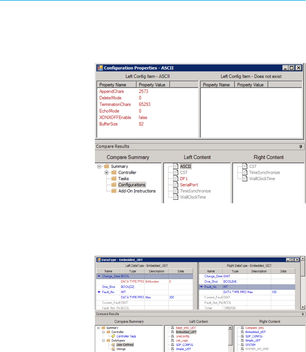
Chapter 3Logix Designer Compare Tool results window
Configuration differences
Any differences found in configuration items are identified in the summary tree. Selecting the summary tree shows
the specific configuration items in which differences were found.
In this example, ASCII, DF1, and SerialPort were found in the left content only. Double-clicking ASCII brings up a
detailed report:
Datatypes differences
Select the Datatypes folder to show the User-Defined and Strings folders. This example shows the differences of
user-defined data types between the two projects.
Rockwell Automation, Inc. LDCT-UM001G-EN-E - December 2023 41

Chapter 3Logix Designer Compare Tool results window
Equipment Sequence differences
Equipment Sequence is a program introduced by Logix Designer to support its sequencing in Logix controllers (also
known as SILC) functionality. Equipment Sequence differences are shown in tabular form like Sequential Function
Chart. Top-level items are as follows:
• Steps
•
Transitions
•
TagConfigurations
The Equipment Sequence program contains a routine called Diagram with Sequence as its type. The SEQ (sequencing)
routine uses steps and transitions. The SEQ routine also has a new section defined in L5X called TagConfigurations.
SEQ routine differences are shown in two tables:
•
One shows the differences on steps and transitions.
•
The other shows the differences on TagConfigurations.
Click <..click to view..> to see the expression content details in a new window.
Function Block Diagram differences
Function Block Diagram compare operations are performed at the sheet level. When a difference is detected between
sheets, the results are shown in a column format. In the following example, the project in Right Sheets has a "compare
only sheet", which does not exist in the Left Sheets project.
42 LDCT-UM001G-EN-E - December 2023 Rockwell Automation, Inc.

Chapter 3Logix Designer Compare Tool results window
The Compare Tool does not align sheets by sheet number; sheets are aligned by content. Within the sheet, the
compare will identify differences between the Left and Right projects.
Ladder Logic differences
Ladder Logic routines are shown in graphical form.
Rockwell Automation, Inc. LDCT-UM001G-EN-E - December 2023 43
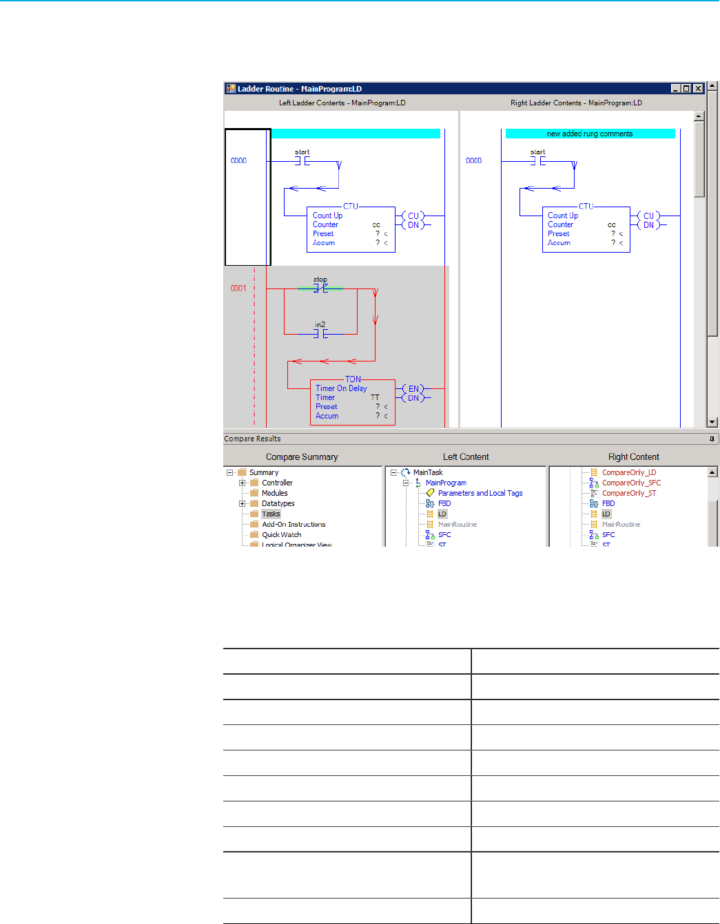
Chapter 3Logix Designer Compare Tool results window
Gray rungs indicate differences between the compared routines; red rungs identify items that are unique to that
project. If the comparison detects a modified rung, the elements of the differing rungs may be further highlighted in
blue. This typically occurs when the rung's structure is the same, but some elements are different.
Designations in Ladder Logic compares
This table shows the designations in the Ladder Logic routine compare.
Designation Meaning
d Delete
D Delete or pending delete rung
e Pending replace rung
i Insert or insert with a replace
I Insert
md Modify or comment changed
mv Move
r Pending replace N (Normal) or pending replace IR (Insert with a
replace)
R Replace
44 LDCT-UM001G-EN-E - December 2023 Rockwell Automation, Inc.

Chapter 3Logix Designer Compare Tool results window
Logical Organizer differences
This folder is only shown if logical organization differences exist between the two projects.
Select Logical Organizer View to show the detailed organization tree. The organization trees are shown the same as
they are within the Logix Designer application.
Modules differences
The Compare Tool application compares the I/O configuration hierarchy and the properties of modules. Duplex-
enabled modules are supported.
Example
For the entire-project compare, the Modules folder appears only when differences exist. Select Modules to view the
I/O Module tree, which is shown as the same way in the Logix Designer application.
Double-click a module in Left Content or Right Content to view details.
Parameter Connections differences
This folder is shown if program parameter differences exist between the two projects.
Rockwell Automation, Inc. LDCT-UM001G-EN-E - December 2023 45
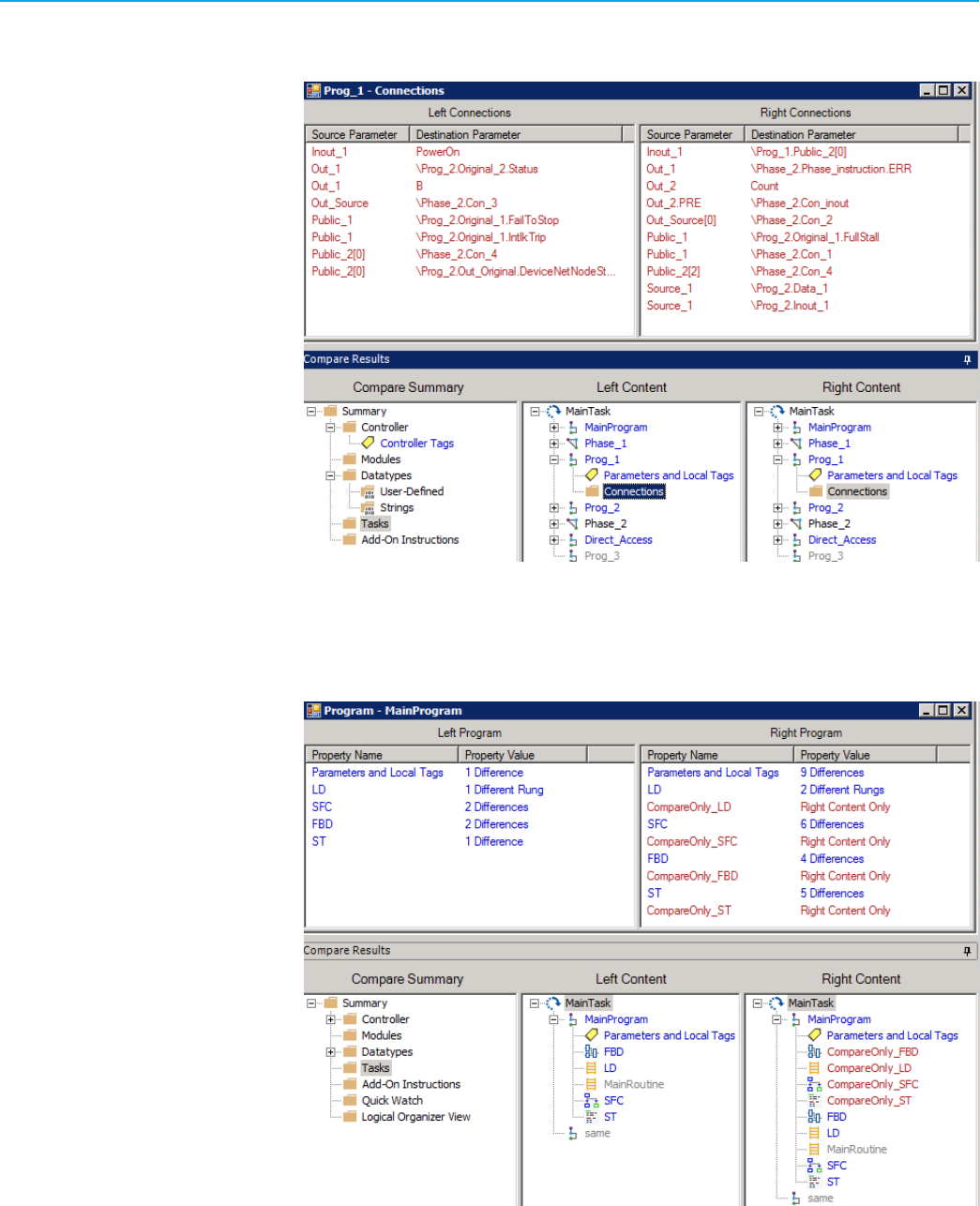
Chapter 3Logix Designer Compare Tool results window
Select the Tasks folder to show the MainTask tree. In this example, differences exist for Connections of Prog_1
between the two projects. Double-click the Connections folder to open the details.
Program differences
This is the example of Program differences. Double-click MainProgram to view the summary of the differences.
46 LDCT-UM001G-EN-E - December 2023 Rockwell Automation, Inc.

Chapter 3Logix Designer Compare Tool results window
Quick Watch differences
This is an example of quick watch differences. Double-click QuickWatch_1 to view the details.
Rung differences
This is an example of rung differences during a partial compare. The rungs are exported from Ladder Logic routines.
Rockwell Automation, Inc. LDCT-UM001G-EN-E - December 2023 47

Chapter 3Logix Designer Compare Tool results window
Sequential Function Chart differences
SFC differences are shown in tabular form like Function Block Diagrams. The results table identifies all SFC items that
did not match. As with other views, differences in common items are shown in blue; items found in a single project
are red. Top-level items are as follows:
•
Steps
•
Transitions
•
Stops
You can see additional details for specific items by expanding an item's tree. Similar items between the Left and Right
views may not line up with each other (that is, there is no synchronization between the views).
Some SFC items can contain embedded structured text. When structured text is used in SFC, the logic is compared.
When differences are found, you will see the name of the structured text property (for example, Preset STX Content)
and next to it, the text <click to view>. Clicking the text brings up a structured text compare view like that described
in the ST section.
Structured Text differences
Structured Text routines are compared by line. Differences are shown in red.
48 LDCT-UM001G-EN-E - December 2023 Rockwell Automation, Inc.
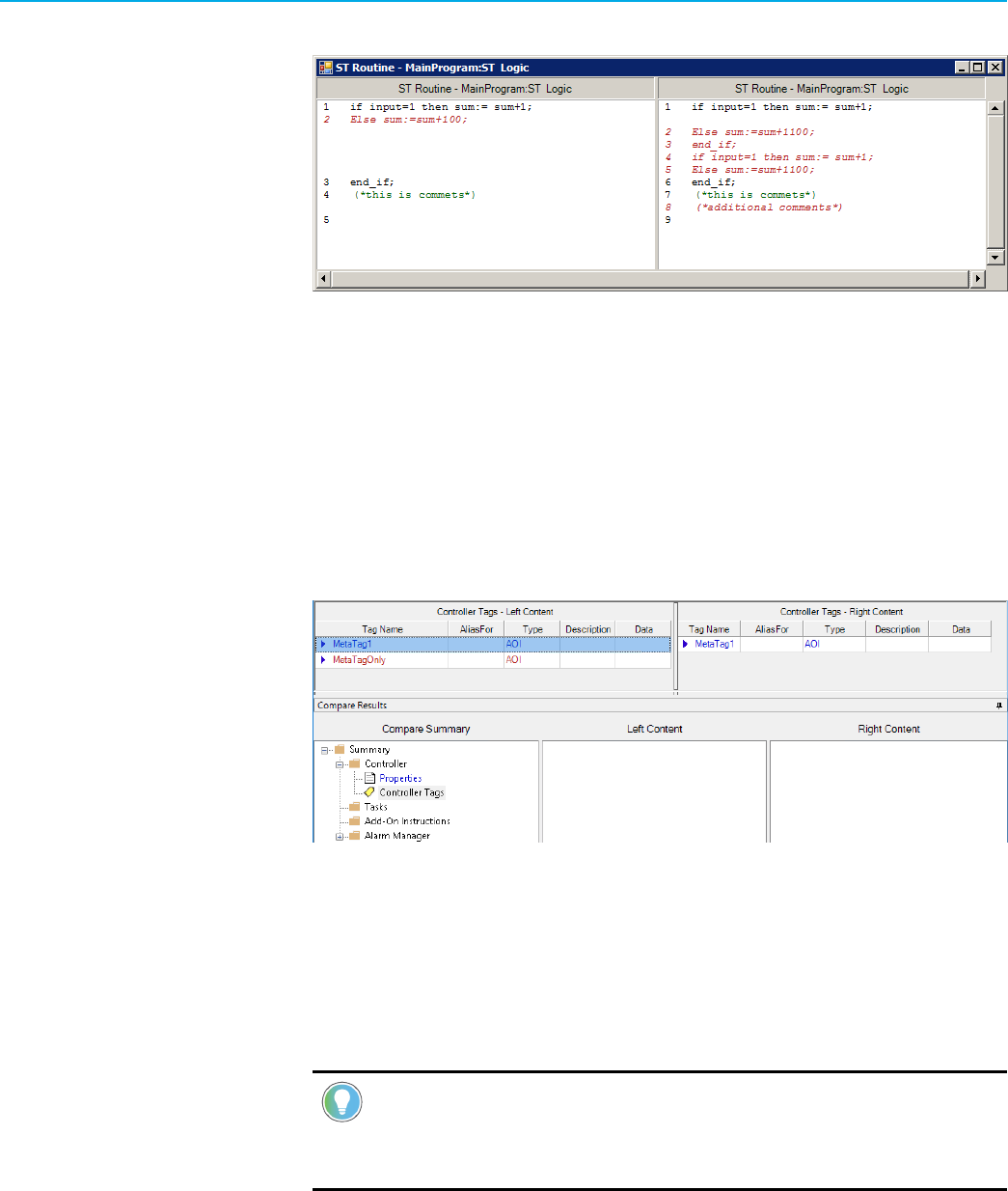
Chapter 3Logix Designer Compare Tool results window
You can include or exclude Structured Text comments and descriptions.
Tag differences
When differences exist, an icon appears under the controller folder in Compare Summary. Double-click Controller
Tags to view tag differences in details.
The Compare Tool application compares the meta data of new tags supported by process controller, like Area and
Instruction. Those meta data can be merged with the tags together. In this example, there are some items that are
common between the two projects (note the blue text). The left content has a MetaTagOnly tag that does not exist in
the Compare project (note the red text).
Large tag compare
When the number of tag members is larger than the default maximum amount, Logix Designer Compare Tool will skip
the compare of the tag data and mark it with a red flag.
The default value is 1000 with unit 10 tag members. That means the maximum supported number of tag members is
10000.
Tip:
If you meet an insucient memory message during comparing large tag, change the
MaxSupportedTagMembers value of Parse.config to another amount lower than 1000 and try again. For
details about Parse.config, refer to Set Global Exclude.
Rockwell Automation, Inc. LDCT-UM001G-EN-E - December 2023 49

Chapter 3Logix Designer Compare Tool results window
In this example, there are multiple large tags in the two projects. The Compare Tool application skips the compare of
these tags and marks them with red flags.
In the tabular view list, after you click the Tag Name cell of a tag, Compare Tool will compare the differences and
show the results in the Logix Designer Compare Tool Large Tag Viewer window.
Task differences
Task differences include task properties or differences in a program's structure.
50 LDCT-UM001G-EN-E - December 2023 Rockwell Automation, Inc.

Chapter 3Logix Designer Compare Tool results window
The Compare Tool application supports comparing and displaying the PlantPAx process instructions. In this example,
The left content has a PAI instruction that does not exist in the MainRoutine of Compare project (see the red box).
License protected Add-On Instructions and routines comparison
The following table describes the different comparison results of license protected Add-On Instructions and Routines
with or without a license.
Projects License protected components
Compare with a
license
Compare without a
license
Compact GuardLogix®
5370 Safety Controller,
CompactLogix™
5370 Controller,
ControlLogix® 5570
Controller, and
GuardLogix® 5570
Safety Controller
projects
Routine or Add-On Instructions The license protected
routines or Add-On
Instructions can be
compared.
The comparison of
license protected
routines or Add-On
Instructions will fail.
Compact GuardLogix
5380 Safety Controller,
CompactLogix
5380 Controller,
CompactLogix 5480
Controller, ControlLogix
5580 Controller, and
GuardLogix 5580 Safety
Controller projects
Routines Locked If the license protected
routine only exists in
one project, it will be
marked as Content
Protected in the
compare result.
If the license protected
routines of the same
type exist in two
projects, they will be
treated as the same
and will not show in the
compare result.
The license protected
routines will not be
compared.
Rockwell Automation, Inc. LDCT-UM001G-EN-E - December 2023 51

Chapter 3Logix Designer Compare Tool results window
Projects License protected components
Compare with a
license
Compare without a
license
Add-On Instructions Locked If the license protected Add-On Instructions only
exist in one project, it will be marked as Content
Protected in the compare result.
If the license protected Add-On Instructions exist
in two projects, the encrypted attributes will not be
compared.
Routines or Add-On
Instructions
Unlocked The license protected
routines or Add-On
Instructions can be
compared.
The comparison of
license protected
routines or Add-On
Instructions will fail.
Supported Library compares
During the comparison of project files with Libraries, the following Library Object data and Instance Data are
extracted from the Logix Designer contents and compared separately:
• Library configuration information
◦
Dependencies on page 53
◦ External references on page 53
◦ Functions on page 54
◦
Interfaces on page 56
◦
Linked Libraries on page 56
◦
Parameters on page 67
◦ Substitutions on page 68
•
Logix Designer components belonged to the Library
•
Library Object attributes of Logix Designer components
•
Instance Data
◦
Instance Libraries
◦ Instance Objects
52 LDCT-UM001G-EN-E - December 2023 Rockwell Automation, Inc.

Chapter 3Logix Designer Compare Tool results window
Dependencies differences
The following example shows the Dependencies differences. The compared items of Dependencies include Tags, Add-
On Instructions, and Data Types. You can click each item to view its content differences and library links differences.
External References differences
This example shows the External References differences.
To bring out the detailed report, select ExtRef 100 or Object.
Rockwell Automation, Inc. LDCT-UM001G-EN-E - December 2023 53
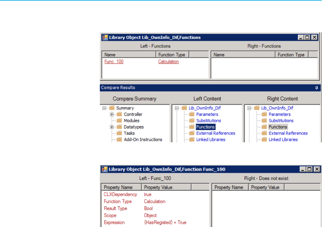
Chapter 3Logix Designer Compare Tool results window
Functions differences
This example shows the Functions differences.
To bring out the detailed report, select Func 100 or Calculation.
Instance Data differences
During the comparison of project files with Instance Data, the Instance Data is processed, compared, and shown in a
separate section. The Instance Data includes Instance Libraries and Instance Objects.
54 LDCT-UM001G-EN-E - December 2023 Rockwell Automation, Inc.

Chapter 3Logix Designer Compare Tool results window
This is an example of the Libraries differences. To see the detailed report, double-click Lib_OwnInfo_Same.
This is an example of the Instance differences. To see the detailed report, double-click
Lib_OwnInfo_Dif.OwnInfo_Dif (1.0).
Rockwell Automation, Inc. LDCT-UM001G-EN-E - December 2023 55

Chapter 3Logix Designer Compare Tool results window
Interfaces differences
This example shows the Interfaces differences.
To view the detailed report, select Link3.
Libraries differences
During comparison, the Library Objects data is extracted, compared, and shown separately. The comparison result of
the Library Objects data is included in the Library Objects folder.
Click Library Objects to view the differences of libraries between the two projects.
56 LDCT-UM001G-EN-E - December 2023 Rockwell Automation, Inc.

Chapter 3Logix Designer Compare Tool results window
In this example, Library Content includes the Logix Designer components belonged to the Library. You can compare
the Logix Designer component differences and view the Library Object attributes of each component.
This example shows the differences of the Lib_OwnInfo_Dif Library. Double-click Lib_OwnInfo_Dif folder to view the
detailed report.
Rockwell Automation, Inc. LDCT-UM001G-EN-E - December 2023 57

Chapter 3Logix Designer Compare Tool results window
Library Object attribute differences of Logix Designer components
During the Library Object data comparison, these Library Object attributes of the Logix Designer components are
compared:
• Add-On Instructions on page 58
• Data Types on page 59
•
Function Block Diagram on page 59
•
I/O Configuration on page 60
•
Ladder Logic on page 61
• Program on page 62
•
Sequential Function Chart on page 62
•
Structured Text on page 63
•
Tag on page 64
•
Task on page 64
•
Trend on page 65
Library Object attribute differences: Add-On Instructions
This is an example of Library Object attribute differences of Add-On Instructions.
To see the detailed attribute report, select Attributes.
58 LDCT-UM001G-EN-E - December 2023 Rockwell Automation, Inc.

Chapter 3Logix Designer Compare Tool results window
Library Object attribute differences: Data Types
Expand the Data Types folder to view the Data Types attribute differences.
Double-click UDT_1, and then click Attributes to view the detailed report.
Library Object attribute differences: Function Block Diagram
This is an example of Library Object attribute differences of Function Block Diagram.
Rockwell Automation, Inc. LDCT-UM001G-EN-E - December 2023 59

Chapter 3Logix Designer Compare Tool results window
Double-click FBD, and then click Logic to view the detailed report. You might drill in multiple levels before the
attribute you want to view is shown.
Library Object attribute differences: I/O Configuration
This example shows the Library Object attribute differences of I/O Configuration. Expand the I/O Configuration
folder, and then double-click 1756-IB16IB16 to view the different items. You can click each item to view the detailed
report.
60 LDCT-UM001G-EN-E - December 2023 Rockwell Automation, Inc.

Chapter 3Logix Designer Compare Tool results window
Library Object attribute differences: Ladder Logic
This example shows the Library Object attribute differences of Ladder Logic.
Double-click LD, and then click Owners or Logic to view the detailed report. This example shows the rung attribute
differences by clicking Logic.
Click either rung to view the Library Object attribute differences. Click Owners to show the detailed report.
Rockwell Automation, Inc. LDCT-UM001G-EN-E - December 2023 61

Chapter 3Logix Designer Compare Tool results window
Library Object attribute differences: Program
This example shows the Library Object attribute differences of Program. Double-click MainProgram to view the
summary of Library Object attribute differences.
Click Attributes to bring out the detailed report.
Library Object attribute differences: Sequential Function Chart
This example shows the Library Object attribute differences of Sequential Function Chart. Click Attributes or Logic
to view the Library Object attribute differences.
62 LDCT-UM001G-EN-E - December 2023 Rockwell Automation, Inc.

Chapter 3Logix Designer Compare Tool results window
Click Logic to view the attribute differences of SFC's Steps, Transitions, and Stops items. Click each item to drill in
until the attribute is shown.
Library Object attribute differences: Structured Text
This example shows the Library Object attribute differences of Structured Text.
To view the detailed attribute differences for each line in the Structured Text, click Logic, and then drill in each line
until the attribute is shown.
Rockwell Automation, Inc. LDCT-UM001G-EN-E - December 2023 63

Chapter 3Logix Designer Compare Tool results window
Library Object attribute differences: Tag
This example shows the Library Object attribute differences of Tag.
In this example, the MT102_MyUDT tag includes Attributes and Tag Value Expressions. Click either item to view the
detailed report.
Library Object attribute differences: Task
This example shows the Library Object attribute differences of Task.
64 LDCT-UM001G-EN-E - December 2023 Rockwell Automation, Inc.

Chapter 3Logix Designer Compare Tool results window
Double-click MainTask, and then click Attributes to view the detailed report.
Library Object attribute differences: Trend
This example shows the Library Object attribute differences of Trend.
Double-click Trend01, and then click Attributes to view the detailed report.
Rockwell Automation, Inc. LDCT-UM001G-EN-E - December 2023 65
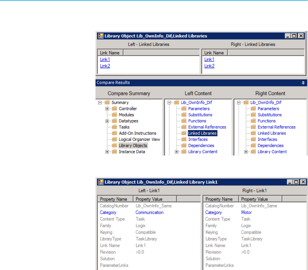
Chapter 3Logix Designer Compare Tool results window
Linked Libraries differences
This example shows the Linked Libraries differences.
Select Link1 to bring out the detailed report.
66 LDCT-UM001G-EN-E - December 2023 Rockwell Automation, Inc.

Chapter 3Logix Designer Compare Tool results window
Parameters differences
Double-click Parameters to view its differences. Click each item to view the detailed report.
This example shows the detailed report of the "ProductName" item.
Rockwell Automation, Inc. LDCT-UM001G-EN-E - December 2023 67

Chapter 3Logix Designer Compare Tool results window
Substitutions differences
Double-click Substitutions to view the detailed differences.
68 LDCT-UM001G-EN-E - December 2023 Rockwell Automation, Inc.

Chapter 4
Master-instance compare results window
Once the master and instance components comparison completes, the compare results show in a dedicated window,
which is different from that of project-to-project comparisons. The master-instance compare results window
includes:
• Master-Instance Pairs pane
•
Master Component pane
•
Instance Component pane
•
Detailed difference report
Information shown in the window is color-coded:
•
Red - Indicates items that exist in one component but not the other.
•
Blue - Indicates items that are common between the two components, but have a difference.
•
Black - Indicates common items that contain child elements.
•
Gray - Indicates common items in which no differences are found.
Master-Instance Pairs pane
The Master-Instance Pairs pane lists the master components and corresponding instance components. All the
instance components are listed as child items of the master component, and are compared with the master
components respectively. On this pane, you can do the following:
•
To view the compare summary, click .
•
To view the compare result, click an instance component.
•
To view the full path and the structural information of a component, point to it.
•
To print a compare report of one master component with its corresponding instance components, right-click
the master component, and then select PDF Report. To print a compare report of all the master and instance
components, select File > Generate Report.
Master Component pane
The Master Component pane shows information specific to the master component once any of its corresponding
instance components is selected.
Instance Component pane
The Instance Component pane shows information specific to the selected instance component.
Detailed difference report
The report shows the detailed differences between the master and instance components.
Rockwell Automation, Inc. LDCT-UM001G-EN-E - December 2023 69

Chapter 5
About Logix Designer Merge Tool
Logix Designer Merge Tool compares two or three Logix Designer projects (ACD, L5K, or L5X) and combines changes
from different projects into the output project. You can perform a two-way merge (a merge of two project files) or
a three-way merge (a merge of three project files). With the Merge Tool, you can merge project elements like tasks,
programs, routines, modules, user-defined data types, parameter connections, tags, Add-On Instructions, trends, and
controller properties.
Because Studio 5000 Logix Designer supports the exportation of multiple components with the same component
type, the Merge Tool supports single-to-single, single-to-multiple, and multiple-to-multiple component merge. If the
component types in the L5X files are different, you cannot proceed due to unmatched component types.
The Merge Tool also allows you to perform two-way or three-way merge with command-line parameters. In the
command-line mode, if the projects to be merged have no unresolved items as a result of the default selections, the
Save as dialog box opens directly for you to save the merge result project.
For project files including Library Objects created with the Application Code Manager Library Designer, the Merge Tool
also supports the merge of Library Objects data on the Library level. The merge of Instanced Library Objects is not
supported.
Before merging project files, the tool compares the different items of the two or three project files.
•
For two-way merge on page 71, the contents are merged from the right project into the left project, which
is assumed as the base project.
•
For three-way merge on page 72, the contents are merged from the right or center project into the left
project. The left project is assumed as the base project, and the center project the original project.
After the comparison completes, a merge result project is constructed automatically. All items only existing in the left
or right project are resolved items, which are merged into the result project. All conflict items are unresolved items,
which need definite selection.
Project Merge dialog box
How do I open the Project Merge dialog box?
•
On the menu bar, select File > New > Project Merge.
or
• On the toolbar, select if you are in the Compare Tool window or select if you are in the Merge Tool
window.
Use the Project Merge dialog box to merge two or three full Logix Designer project files or partial L5X files.
For partial merge, the Merge Tool only supports single module merges. Force data can be exported with different
data formats depending on the Logix Designer versions. In partial merge, only force data of the same format can be
merged. When merging force data with different formats, a dialog box opens, which allows you to cancel the merge or
continue to merge without force data.
Tip:
For both two-way and three-way merges, the project file versions must be version 17 or higher.
70 LDCT-UM001G-EN-E - December 2023 Rockwell Automation, Inc.

Chapter 5About Logix Designer Merge Tool
The version of the left project file must be equal to or higher than the version of the right project file and
the center project file (if in three-way merge mode).
With the merge tool, you can:
•
Use the breadcrumb navigation bar to locate conflict items during the merge operation.
•
Navigate to items marked in different colors to view detailed differences.
•
Select the contents on the left, center, or right project to resolve unresolved items.
•
Save the result project in the ACD, L5K, or L5X format, which can be opened with the Logix Designer
application.
Related information
About unresolved items on page 87
Logix Designer Merge Tool results window on page 83
Merge two project files
Use Logix Designer Merge Tool to merge two entire Logix Designer project files or two partial L5X files exported with
single or multiple components.
Tip:
To merge the two project files you compared, in the Logix Designer Compare Tool window, select
File > Merge or select . If you compared the projects with the Include tags checkbox cleared, an error
message displays before the merge starts, indicating that the excluded tags will be needed for the merge.
Select OK to start the merge with all the tags included.
To perform a two-way merge
1.
Open Project Merge by using one of these methods:
◦
On the menu bar, select File > New > Project Merge.
◦ On the toolbar, select if you are in the Compare Tool window or select if you are in the Merge
Tool window.
2.
Specify the project files to be merged in these boxes:
◦
Left Content
◦ Right Content
Tip:
Enter the full path of the project file or select (Browse) to locate the ACD, L5K, or L5X
file on the hard drive or network.
3.
Select OK to start the two-way merge.
4.
(optional) Select to save the merge result project as an ACD, L5K, or L5X file.
Tip:
Before saving a merge project, make sure that all unresolved items are resolved.
Rockwell Automation, Inc. LDCT-UM001G-EN-E - December 2023 71

Chapter 5About Logix Designer Merge Tool
Merge three project files
Use Logix Designer Merge Tool to merge three entire Logix Designer project files or three partial L5X files exported
with single or multiple components.
To perform a three-way merge
1.
Open Project Merge by using one of these methods:
◦
On the menu bar, select File > New > Project Merge.
◦ On the toolbar, select if you are in the Compare Tool window or select if you are in the Merge
Tool window.
2.
In Project Merge, select the Include original content checkbox.
Tip:
By default, Include original content is not selected and the Original Content box is not
available, which means you can only start a two-way merge.
3.
Specify the project files to be merged in these boxes:
◦
Left Content
◦ Right Content
◦ Original Content
Tip:
Enter the full path of the project file or select (Browse) to locate the ACD, L5K, or L5X
file on the hard drive or network.
4.
Select OK to start the three-way merge.
5.
(optional) Select to save the merge result project as an ACD, L5K, or L5X file.
Tip:
Before saving a merge project, make sure that all unresolved items are resolved.
Settings in the Project Merge dialog box
The Project Merge dialog box includes these settings:
Setting Description
Left Content Specify the full path of the ACD, L5K, or L5X file that shows on
the left side of the merge.
Right Content Specify the full path of the ACD, L5K, or L5X file that shows on
the right side of the merge.
Include original content Select to turn on the Original Content box that is used to
specify the original content of the merge.
Original Content Specify the full path of the ACD, L5K, or L5X file as the original
content of the merge.
Select Include original content to turn on this box.
72 LDCT-UM001G-EN-E - December 2023 Rockwell Automation, Inc.

Chapter 5About Logix Designer Merge Tool
Logix Definition Merge dialog box
How do I open the Logix Definition Merge dialog box?
•
On the menu bar, select File > New > Logix Definition Merge.
Use the Logix Definition Merge dialog box to merge Logix definitions only, which are Add-On Instructions and User-
defined Data Types. Alarm definitions associated with Add-On Instructions and User-defined Data Types are also
included in the merge operation. Other components are not compared or merged.
Merge two Logix definitions
Use Logix Designer Merge Tool to merge two Logix definitions in the project files.
Tip:
To merge the two Logix definitions that you compared, in the Logix Designer Compare Tool window,
select File > Merge or select .
To merge two Logix definitions
1.
On the menu bar, select File > New > Logix Definition Merge.
2.
Specify the project files to be merged in these boxes:
◦
Left Content
◦ Right Content
Tip:
Enter the full path of the project file or select (Browse) to locate the ACD, L5K, or L5X
file on the hard drive or network.
3. Select OK to start the merge of two Logix definitions.
4.
(optional) Select to save the merge result project as an ACD, L5K, or L5X file.
Tip:
Before saving a merge project, make sure that all unresolved items are resolved.
Merge three Logix definitions
Use Loigx Designer Merge Tool to merge three Logix definitions in the project files.
To merge three Logix definitions
1. On the menu bar, select File > New > Logix Definition Merge.
2.
In Project Merge, select the Include original content checkbox.
Tip:
By default, Include original content is not selected and the Original Content checkbox is
not available, which means you can only start a two-way merge.
Rockwell Automation, Inc. LDCT-UM001G-EN-E - December 2023 73
Chapter 5About Logix Designer Merge Tool
3. Specify the project files to be merged in these boxes:
◦
Left Content
◦ Right Content
◦ Original Content
Tip:
Enter the full path of the project file or select (Browse) to locate the ACD, L5K, or L5X
file on the hard drive or network.
4.
Select OK to start the merge of three Logix definitions.
5.
(optional) Select to save the merge result project as an ACD, L5K, or L5X file.
Tip:
Before saving a merge project, make sure that all unresolved items are resolved.
Settings in the Logix Definition Merge dialog box
The Logix Definition Merge dialog box includes these settings:
Setting Description
Left Content Specify the full path of the ACD, L5K, or L5X file that shows on
the left side of the merge.
Right Content Specify the full path of the ACD, L5K, or L5X file that shows on
the right side of the merge.
Include original content Select to turn on the Original Content box that is used to
specify the original content of the merge.
Original Content Specify the full path of the ACD, L5K, or L5X file as the original
content of the merge.
Select Include original content to turn on this box.
Supported command-line merge operations
Logix Designer Merge Tool supports using command-line parameters to merge two or three project files without
interacting with the user interface.
NOTE:
To use command-line parameters, users must have permission to the Compare: Execute
security policy in FactoryTalk Administration Console. See Secure Logix Designer Compare Tool for
details.
Use command-line parameters to merge two project files
Logix Designer Merge Tool supports using command-line parameters to merge two project files.
Tip:
74 LDCT-UM001G-EN-E - December 2023 Rockwell Automation, Inc.

Chapter 5About Logix Designer Merge Tool
Command-line parameters are case-insensitive. If a specified value includes a space, you must enclose
the value in quotation marks (for example, "value with spaces").
To merge two project files with command lines
1.
Open the Windows Command Prompt window.
2.
Enter commands to specify the merge parameters, each of which are separated by a space.
a.
Specify the use of the Compare Tool.
RSLCompare
b. Specify the merge command.
-m
c.
Specify the path and file name of the left project.
For example, "C:\Users\Public\Documents\Project_base.ACD"
d. Specify the path and file name of the right project.
For example, "C:\Users\Public\Documents\Project_compare.ACD"
e.
(optional) Specify the path and file name of the output project.
For example, -o "C:\Users\Public\Documents\mergeResult.ACD"
f.
(optional) Specify the use of title name for each project in the Merge Tool window.
Tip:
This function is only supported in the command-line mode.
For example, -t "Base File" "Compare File"
g.
(optional) Define the performance mode for the comparing process as Fastest Compare that shortens
comparing time with a potential of running out of memory or Memory Saver that saves memory
occupation with a potential of increasing comparing time.
Tip:
This must be the last command-line parameter in the entire command line. If you don't
use this parameter, the performance mode will be the one set on the menu bar through
Options > Performance.
▪
For the Fastest Compare mode: -PM FastestCompare
▪
For the Memory Saver mode: -PM MemorySaver
This is an example of the complete command lines with the Memory Saver performance mode
specified.
3.
Press Enter.
Use command-line parameters to merge three project files
Logix Designer Merge Tool supports using command-line parameters to merge three project files. When specifying
the path and file name of the projects to merge or the title names for each project, make sure to do it in the
sequential order of left, right, and center projects.
Tip:
Rockwell Automation, Inc. LDCT-UM001G-EN-E - December 2023 75

Chapter 5About Logix Designer Merge Tool
Command-line parameters are case-insensitive. If a specified value includes a space, you must enclose
the value in quotation marks (for example, "value with spaces").
To merge three project files with command lines
1.
Open the Windows Command Prompt window.
2.
Enter commands to specify the merge parameters, each of which are separated by space.
a.
Specify the use of the Compare Tool.
RSLCompare
b. Specify the merge command.
-m
c.
Specify the path and file name of the left project.
For example, "C:\Users\Public\Documents\Project_base.ACD"
d. Specify the path and file name of the right project.
For example, "C:\Users\Public\Documents\Project_compare.ACD"
e.
Specify the path and file name of the center project.
For example, "C:\Users\Public\Documents\Project_center.ACD"
f.
(optional) Specify the path and file name of the output project.
For example, -o "C:\Users\Public\Documents\mergeResult.ACD"
g.
(optional) Specify the use of title name for each project in the Merge Tool window.
Tip:
This function is only supported in the command-line mode.
For example, -t "Base File" "Compare File" "Center File"
h.
(optional) Define the performance mode to use for the comparing process as Fastest Compare that
shortens comparing time with a potential of running out of memory or Memory Saver that saves
memory occupation with a potential of increasing comparing time.
Tip:
This needs to be the last command-line parameter in the entire command line. If
you don't use this parameter, the performance mode will be the one set on the menu bar
through Options > Performance.
▪
For the Fastest Compare mode: -PM FastestCompare
▪
For the Memory Saver mode: -PM MemorySaver
This is an example of the complete command lines with the Memory Saver performance mode
specified.
3.
Press Enter.
76 LDCT-UM001G-EN-E - December 2023 Rockwell Automation, Inc.

Chapter 5About Logix Designer Merge Tool
Logix Designer Merge Tool windows
This example shows the Logix Designer Merge Tool window in a two-way merge mode:
This example shows the Logix Designer Merge Tool window in a three-way merge mode:
Rockwell Automation, Inc. LDCT-UM001G-EN-E - December 2023 77

Chapter 5About Logix Designer Merge Tool
Operations after the merge
This table shows the operations that you can apply after the merge is done.
To... Do this...
View detailed differences among the left, right, or center (if in
three-way merge mode) projects
Point to an item line, and then select (Expand) or
double-click the item line.
Choose an item with differences In the item line, select the checkbox besides the item to choose.
In Structure Text or Function Block Diagram logic line, you can
select multiple items. Press Shift or Ctrl to select the items and
press the space key to select or clear multiple selections.
Tip: The checkboxes in the same line are mutually exclusive.
For example, if you select a checkbox of the left project, the
checkbox in the same line of the right or center project (if in
three-way merge mode) is cleared.
Choose all items with differences of the left project
On the toolbar, select (Take All Left).
Choose all items with differences of the center project (if in
three-way merge mode)
On the toolbar, select (Take All Center).
Choose all items with differences of the right project
On the toolbar, select (Take All Right).
View the next section that contains different items
On the toolbar, select (Next Difference Section).
View the previous section that contains different items
On the toolbar, select (Previous Difference Section).
View the next section that contains unresolved items
On the toolbar, select (Next Unresolved Section).
View the previous section that contains unresolved items
On the toolbar, select (Previous Unresolved Section).
Revert changes that you have made
On the toolbar, select (Undo) or (Redo).
Tip: You can undo or redo up to 100 actions. The changes
cannot be reverted if you leave the current merge window.
Go back to other items On the breadcrumb navigation bar, select (Home) or other
items.
Merge Tool menu bar
The Logix Designer Merge Tool menu bar contains these menu items:
Menu Option Shortcut Description
New > Project Merge Ctrl + N Opens the Project Merge
dialog box to merge two or
three projects.
File
New >Logix Definition Merge None Opens the Logix Definition
Merge dialog box to merge
Logix definitions from two or
three project files.
78 LDCT-UM001G-EN-E - December 2023 Rockwell Automation, Inc.

Chapter 5About Logix Designer Merge Tool
Menu Option Shortcut Description
Open Ctrl + O Opens the merge result project
file in the Logix Designer
application.
Tip: This item is enabled after
you save the merge result
project.
Close None Closes the current merge
project and returns to the
Logix Designer Merge Tool
window.
Close Merge None Closes the Logix Designer
Merge Tool window and
returns to the Logix Designer
Compare Tool window.
Save Ctrl + S Opens the Save As dialog box
to save the current merge
result project.
Save As None Opens the Save As dialog box
to save the current merge
result project with another
name or type.
Exit None Closes the Logix Designer
Merge Tool window and exits
the Logix Designer Compare
Tool application.
Take Left Ctrl + L Uses all current items and
child items of the left project
to the merge result project.
Take Center Ctrl + T Uses all current items and
child items of the center
project to the merge result
project.
Tip: This option is available
only in the three-way merge
mode.
Take Right Ctrl + R Uses all current items and
child items of the right project
to the merge result project.
Undo Ctrl + Z Undoes the previous merge
operation.
Edit
Redo Ctrl + Y Redoes the merge operation
that you undo.
Rockwell Automation, Inc. LDCT-UM001G-EN-E - December 2023 79
Chapter 5About Logix Designer Merge Tool
Menu Option Shortcut Description
Previous Difference Section Shift + F7 Opens the previous section
that contains different items.
Next Difference Section F7 Opens the next section that
contains different items.
Previous Unresolved Section Shift + F8 Opens the previous section
that contains unresolved
items.
Next Unresolved Section F8 Opens the next section that
contains unresolved items.
Show Hidden Tags None Shows hidden tags when you
view or merge tag differences.
Tip: The option only works for
Controller tags and Program
tags. It does not work for
Parameters and Local Tags
under AOI.
Show Main Operand
Descriptions
None Shows main operand
descriptions in ladder routines.
Show Additional Ladder
Context
None Shows all rungs in ladder for
context purposes.
Performance > Fastest
Compare
None Defines the comparison mode
as shortening comparing time
with a potential of running out
of memory.
Performance > Memory Saver None Defines the comparison mode
as saving memory occupation
with a potential of increasing
comparing time.
Option
Documentation Languages None Shows the project
documentation languages.
Errors None Shows the Errors pane that
lists errors when you save the
merge result project.
View
MergeResult None Shows the merge result pane
that lists the resulting project.
Index None Opens the online help.
Release Notes None Opens the release notes.
Help
About Logix Designer Compare
Tool
None Opens the About Logix
Designer Compare Tool
dialog box to view the
80 LDCT-UM001G-EN-E - December 2023 Rockwell Automation, Inc.

Chapter 5About Logix Designer Merge Tool
Menu Option Shortcut Description
program, version, and
copyright information.
Merge Tool toolbar
In two-way merge:
In three-way merge:
The toolbar contains shortcuts to several commonly used functions in Logix Designer Merge Tool. The toolbar button
is a graphical representation of a command that is also available from the Logix Designer Merge Tool menu bar.
The toolbar includes these buttons:
Toolbar Button Menu Command Shortcut Description
File > New > Project Merge Ctrl + N Opens the Project Merge
dialog box, from which you can
merge two or three projects.
File > Open Ctrl + O Opens the merge result project
file in the Logix Designer
application.
Tip: This item is enabled after
you save the merge result
project.
File > Save Ctrl + S Opens the Save As dialog box,
from which you can save the
current merge project.
Edit > Take Left Ctrl + L Uses all current items and
child items of the left project
to the merge result project.
Edit > Take Center Ctrl + T Uses all current items and
child items of the center
project to the merge result
project.
Edit > Take Right Ctrl + R Uses all current items and
child items of the right project
to the merge result project.
Edit > Undo Ctrl + Z Undoes the previous merge
operation.
Rockwell Automation, Inc. LDCT-UM001G-EN-E - December 2023 81

Chapter 5About Logix Designer Merge Tool
Toolbar Button Menu Command Shortcut Description
Edit > Redo Ctrl + Y Redoes the merge operation
that you undo.
Edit > Previous Difference
Section
Shift + F7 Opens the previous section
that contains different items.
Edit > Next Difference Section F7 Opens the next section that
contains different items.
Edit > Previous Unresolved
Section
Shift + F8 Opens the previous section
that contains unresolved
items.
Edit > Next Unresolved Section F8 Opens the next section that
contains unresolved items.
82 LDCT-UM001G-EN-E - December 2023 Rockwell Automation, Inc.

Chapter 6
Logix Designer Merge Tool results window
Once Logix Designer Merge Tool completes the comparison, it shows a constructed merge result project
automatically. By default, the project contains:
• Same contents in the left, right, or center projects.
• New contents that only exist in the left or right project. Logix Designer Merge Tool assumes that these
contents are added, not deleted. Hence, contents will be selected by default.
•
Collision contents that exist in two or three of the left, right and center projects (if in three-way merge
mode) but the contents are different. You must manually resolve differences in these unresolved items.
Tip:
For three-way merges, two of the three items could be the same based on the compare
result. In such cases, the same two items are marked as gray, while the other different item is
marked as black.
The differences are shown in different colors:
•
Black - Default color.
•
Blue - Indicates items that are unresolved or contain unresolved items.
•
Gray - Indicates items that are the same or cannot be merged in both projects.
•
Red - Indicates items that are listed under other parent items.
The window includes left, center (if in three-way merge mode), right, and result panes.
About left, center, and right panes
The left, center, and right panes show details of the two (in two-way merge) or three (in three-way merge) Logix
Designer projects. You can navigate into items to view the detailed differences or select the desired conflict items.
Example
In two-way merge
Rockwell Automation, Inc. LDCT-UM001G-EN-E - December 2023 83

Chapter 6Logix Designer Merge Tool results window
In three-way merge
Icons in the left, center, or right pane
This table shows the icons in the left, center, or right pane.
Icon
*
Description
Indicates the item and all its child items will be merged into the
result project.
Indicates the item and all its child items will not be merged into
the result project.
Indicates some of its child items will be merged into the result
project.
Indicates that the item will be merged into the result project
and cannot be excluded by clearing this checkbox.
However, if the item has a parent item, you can clear the parent
item to exclude it.
Indicates that the item will not be merged into the result project
and cannot be included by selecting this checkbox.
However, if the item has a parent item, you can select the
parent item to include it.
* These icons might look different depending on the Windows theme used on your computer.
Default selection rules
For two-way merges, the default selection rules are as follows:
Rule Left Project Right Project
Assume left (changed) A
Assume right (changed) A
Unresolved (conflict) A A, changed
Tip:
In a two-way merge, the application cannot determine if the content is added or removed between
the two files. The merge tool makes the assumption that the content has been added by default.
84 LDCT-UM001G-EN-E - December 2023 Rockwell Automation, Inc.

Chapter 6Logix Designer Merge Tool results window
For three-way merges, the default selection rules are as follows:
Rule Left Project Center Project Right Project
Assume left (no change) A A A
Assume left (changed) A, changed A A
Assume right (changed) A A A, changed
Assume left (changed) B A B
Assume left (deleted) -, deleted A A
Assume right (deleted) A A -, deleted
Assume left (deleted) -, deleted A -, deleted
Assume left (added) A
Assume right (added) A
Assume left (added) A A
Unresolved (conflict) A, changed A, changed
Unresolved (conflict) A, changed A A, changed
Unresolved (conflict) -, deleted A A, changed
Unresolved (conflict) A, changed A -, deleted
About the result pane
The result pane shows the merge result project information in a hierarchy tree. By default, the result pane contains:
•
Items that only exist in the left project.
• Items that only exist in the right project.
• Items with common differences among the three projects (if in three-way merge mode).
•
Items with no differences between projects.
You can double-click the item to view details. You can also undock the merge result pane by clicking and dragging or
double-clicking its title bar. To dock the result pane back to the results window, double-click its title bar.
Icons in the result pane
When you resolve the conflict items by selecting items on the left, center, or right project, these icons display:
Icon Description
Indicates the items from the left project.
Indicates the items from the right project.
Indicates the items from the center project.
Indicates the items from more than one project.
Indicates the items removed from the Library.
blank Indicates no differences found for the current item.
Rockwell Automation, Inc. LDCT-UM001G-EN-E - December 2023 85

Chapter 6Logix Designer Merge Tool results window
Example
About the navigation map
Logix Designer Merge Tool uses colors to highlight differences on the vertical thumbnail scroll bar. You can quickly
navigate by clicking in the navigation map to go to that area in the routine. When you change an item, the color is
also updated to reflect the state.
Tip:
Navigation map only exists in ladder and Structure Text routines.
Example
In two-way merge
86 LDCT-UM001G-EN-E - December 2023 Rockwell Automation, Inc.

Chapter 6Logix Designer Merge Tool results window
In three-way merge
About unresolved items
In Logix Designer Merge Tool, unresolved items are shown in blue. These items exist in two or three of the left, right,
and center projects (if in three-way merge mode) but the contents are different. If an item is unresolved, its parent
element is also marked as unresolved.
You must resolve these differences manually. Before saving a merge project, make sure that all unresolved items are
resolved.
Tip:
While resolving items during a single-to-single component merge:
•
If the selections are all from the left pane or from both sides of the pane, the merge result will
use the left item's name.
• If the selections are all from the right pane, the merge result will use the right item's name.
Supported merge types
The supported merge types are as follows:
Merge Type Level
Add-On Instructions AOI
Alarm Manager Property
Equipment Sequence Steps, transitions, and TagConfigurations
Tip: This only applies when the structures of the whole SEQ
(sequencing) routines are the same among the left, right, and
center (if in three-way merge mode) projects.
Function Block Diagram Sheet
Ladder Diagram Rung
Library Whole library
Logix definition Add-On Instructions and DataTypes
Rockwell Automation, Inc. LDCT-UM001G-EN-E - December 2023 87

Chapter 6Logix Designer Merge Tool results window
Merge Type Level
Modules Properties
Sequential Function Chart Steps, transitions, and actions
Tip: This only applies when the structures of the whole SFCs
are the same among the left, right, and center (if in three-way
merge mode) projects.
Structure Text Line
Logix Designer Merge Tool supports displaying safety signatures in Add-On Instructions, Modules, Programs, Routines,
Tags, and Tasks.
Tip:
These detailed merges are not supported:
•
Pending or test edits
All pending or test edits are removed from the merge result. You cannot perform a detailed merge
of any rung if a ladder routine has pending or test edits.
•
Quick Watch
Items of the left project are used in the result project.
Add-On Instructions merge
Logix Designer Merge Tool supports the AOI level merge of Add-On Instructions. For signed Add-On Instructions, all
Local Tags and routines with differences can be shown in merge result tree, but signed Add-On Instructions are
marked as Content Protected in the compare result. You can only view the detailed differences of Local Tags and
routines, but you cannot merge them.
Logix Designer project files can be protected by FactoryTalk Security, license, or source key protection. For project
files of version 32.00 or later, encrypted Add-On Instructions are merged based on the hash value differences. The
encrypted Add-On Instructions are shown as Content Protected and marked as Protected in the merge details pane.
The LogicHash or DescriptionHash properties are not shown. You can only select the entire Add-On Instructions to
merge.
These rules apply to two-way and three-way merges.
88 LDCT-UM001G-EN-E - December 2023 Rockwell Automation, Inc.

Chapter 6Logix Designer Merge Tool results window
This is a merge example of encrypted Add-On Instructions from Logix Designer project files version 32.00 with source
protection. You can drill in to view the detailed properties, but you can only merge on the AOI level.
Alarm Manager merge
Logix Designer supports the creation of Alarm Manager, which contains Alarm Definitions and Alarms.
Example
Alarm Definitions merge
Drill in to view the detailed property differences of the definitions.
Alarms merge
Rockwell Automation, Inc. LDCT-UM001G-EN-E - December 2023 89

Chapter 6Logix Designer Merge Tool results window
Drill in to view the detailed property differences of the alarms.
Equipment Sequence merge
You can merge steps, transitions, or TagConfigurations if structures of the whole SEQ (sequencing) routines are the
same among the left, right and center (if in three-way merge mode) projects. You can only select the entire left, right,
or center routine if structures are different.
An Equipment Sequence Program always has a SEQ routine called Diagram. So a project-only SEQ routine can only be
selected or not selected to be included in the merge. Only SEQ routines that are the same or with common differences
can be individually merged.
Example: Supported SEQ routine
In two-way merge
90 LDCT-UM001G-EN-E - December 2023 Rockwell Automation, Inc.

Chapter 6Logix Designer Merge Tool results window
In three-way merge
Example: Unsupported SEQ routine
In two-way merge
In three-way merge
Function Block Diagram merge
Logix Designer Merge Tool supports the sheet level merge of Function Block Diagram routines. Click the expand icon
or double-click a line to view details. Editing is not available.
Pending or test edit contents cannot be merged, and all these contents are removed in the final merge result.
Example
Rockwell Automation, Inc. LDCT-UM001G-EN-E - December 2023 91

Chapter 6Logix Designer Merge Tool results window
In two-way merge
In three-way merge
Ladder merge
Logix Designer Merge Tool supports the rung level merge of ladder routines. Ladder routine differences are shown in
graphical form as follows:
• For rung level merges, all pending or test edit contents are removed in the final merge result.
• If none of the rungs includes pending or test edit contents, you can reorder rungs in the result pane. If all the
rungs are only taken from the left, center, or right project, you cannot reorder the rungs in the result pane.
92 LDCT-UM001G-EN-E - December 2023 Rockwell Automation, Inc.

Chapter 6Logix Designer Merge Tool results window
For large projects, you can quickly navigate differences and items by using the navigation map, a vertical thumbnail
scroll bar on the left.
Example
In two-way merge
In three-way merge
Designations in ladder merge
This table shows the designations in the ladder merge.
Rockwell Automation, Inc. LDCT-UM001G-EN-E - December 2023 93

Chapter 6Logix Designer Merge Tool results window
Designation Meaning
d Delete
D Delete or pending delete rung
e Pending replace rung
i Insert or insert with a replace
I Insert
md Modify or comment changed
mv Move
r Pending replace N (Normal) or pending replace IR (Insert with a
replace)
R Replace
Library merge
Logix Designer Merge Tool supports the library level merge of Libraries. For Logix Designer project files with Library
Object data, the Library merge result is determined by the selection of Libraries and Logix Designer contents. The
Library Object data includes Library configuration information, Logix Designer components of the Library, and Library
Object attributes of Logix Designer components. The rules for Library Object selection are:
•
Library configuration information follows the Library selection.
•
Logix Designer components of a Library follow the Logix Designer content selection. If a component is
removed from the result project, it is also removed from the Library it belongs to.
• Library attributes of Logix Designer components follow the Library selection.
The merge of Instanced Library Objects is not supported. When merging projects with Instanced Library Objects,
you will be notified that the Library Objects will not be shown or included in the merge result. The Instanced Library
Objects will also be removed when saving the project file.
In the Library merge result, all the Library-related data is organized in a separate section. The detailed merge of
Library configuration information and Logix Designer components of a Library are not supported. You can only click
the expand icon or double-click an item to view details.
In the following example, "CompareOnly_ST" exits as a Logix Designer component belonged to the "AIn" Library, and
only exists in the right Logix Designer project. During the merge process, if the left project is selected, the component
94 LDCT-UM001G-EN-E - December 2023 Rockwell Automation, Inc.

Chapter 6Logix Designer Merge Tool results window
is removed from the result project. Thus, it is removed from the Library it belongs to. An "X" icon in the result
project indicates that it is removed.
Logix definition merge
Only Logix definition components with differences are shown in the merge window.
Example
Logix definition merge
In the merge result pane, merge type icons only show before Logix definition components.
Rockwell Automation, Inc. LDCT-UM001G-EN-E - December 2023 95

Chapter 6Logix Designer Merge Tool results window
Sequential Function Chart merge
You can merge steps, transitions, or actions if the structures of the whole Sequential Function Charts are the same
among the left, right, and center (if in three-way merge mode) projects. You can only select the entire left, right, or
center routine if the structures are different.
Pending or test edit contents cannot be merged, and all these contents are removed in the final merge result.
Example
In two-way merge
In three-way merge
Example: Unsupported SFC
96 LDCT-UM001G-EN-E - December 2023 Rockwell Automation, Inc.

Chapter 6Logix Designer Merge Tool results window
In two-way merge
In three-way merge
Structure Text merge
Logix Designer Merge Tool supports the line level merge of Structure Text routines. For large projects, you can quickly
navigate differences and items by using the navigation map, a vertical thumbnail scroll bar on the left.
To select multiple lines, press Shift or Ctrl and select the checkboxes.
Pending or test edit contents cannot be merged, and all these contents are removed in the final merge result.
Example
In two-way merge
Rockwell Automation, Inc. LDCT-UM001G-EN-E - December 2023 97

Chapter 6Logix Designer Merge Tool results window
In three-way merge
Navigation bar
The breadcrumb navigation bar helps you get back to where you start during the merge operation.
Example
Select the Programs or MainProgram item to view the conflict child elements that it contains or select (Home) to
get back to the root elements.
98 LDCT-UM001G-EN-E - December 2023 Rockwell Automation, Inc.

Chapter 7
Legal Notices
Rockwell Automation publishes legal notices, such as privacy policies, license agreements, trademark disclosures,
and other terms and conditions on the Legal Notices page of the Rockwell Automation website.
Software and Cloud Services Agreement
Review and accept the Rockwell Automation Software and Cloud Services Agreement here.
Open Source Software Licenses
The software included in this product contains copyrighted software that is licensed under one or more open-source
licenses.
You can view a full list of all open-source software used in this product and their corresponding licenses by opening
the oss_license.txt file in your product's OPENSOURCE folder on your hard drive. This file is divided into these
sections:
•
Components
Includes the name of the open-source component, its version number, and the type of license.
•
Copyright Text
Includes the name of the open-source component, its version number, and the copyright declaration.
•
Licenses
Includes the name of the license, the list of open-source components citing the license, and the terms of the
license.
The default location of this file is:
C:\Program Files (x86)\Common Files\Rockwell\Help\Logix Designer Compare Tool Release Notes\OPENSOURCE
\oss_licenses.txt.
You may obtain Corresponding Source code for open source packages included in this product from their respective
project websites. Alternatively, you may obtain the complete Corresponding Source code by contacting Rockwell
Automation via the Contact form on the Rockwell Automation website: https://www.rockwellautomation.com/global/
about-us/contact/contact.page. Please include "Open Source" as part of the request text.
Commercial Software Licenses
This software also includes these commercially licensed software components:
Component Copyright
Spread.Net 16.2.20231.0 Copyright 2002-2023 GrapeCity Inc.
Infragistics Ultimate UI for Windows Forms 23.1 Copyright 2001-2023 Infragistics, Inc.
Rockwell Automation, Inc. LDCT-UM001G-EN-E - December 2023 99

Rockwell Automation Support
Use these resources to access support information.
Technical Support Center Find help with how-to videos, FAQs, chat, user forums, and product notification updates. rok.auto/support
Knowledgebase Access Knowledgebase articles. rok.auto/knowledgebase
Local Technical Support Phone Numbers Locate the telephone number for your country. rok.auto/phonesupport
Literature Library Find installation instructions, manuals, brochures, and technical data publications. rok.auto/literature
Product Compatibility and Download Center
(PCDC)
Get help determining how products interact, check features and capabilities, and find
associated firmware.
rok.auto/pcdc
Documentation feedback
Your comments help us serve your documentation needs better. If you have any suggestions on how to improve our content, complete the form at rok.auto/docfeedback.
Waste Electrical and Electronic Equipment (WEEE)
At the end of life, this equipment should be collected separately from any unsorted municipal waste.
Rockwell Automation maintains current product environmental information on its website at rok.auto/pec.
Rockwell Otomasyon Ticaret A.Ş. Kar Plaza İş Merkezi E Blok Kat:6 34752 İçerenköy, İstanbul, Tel: +90 (216) 5698400 EEE Yönetmeliğine Uygundur
LDCT-UM001G-EN-E - December 2023
Supersedes Publication LDCT-UM001F-EN-E - April 2023
Copyright © 2023, Rockwell Automation Technologies, Inc. All rights reserved. Printed in the U.S.A.
