
Scorpio
®
NRG
®
CR & PS
Single Radius Primary Knee System
Surgical Protocol
PR
This document is intended to be used by healthcare professionals only.
Posterior Referencing

Scorpio NRG
PR Single Radius Primary Knee System
Surgical Protocol
Table of Contents
Xcelerate Instrumentation Surgical Technique
For Scorpio NRG Single Radius Primary Knee System
Exposure . . . . . . . . . . . . . . . . . . . . . . . . . . . . . . . . . . . . . . . . . . . . . . . . . . . . . . . . . . . . . . .1
Femoral Preparation . . . . . . . . . . . . . . . . . . . . . . . . . . . . . . . . . . . . . . . . . . . . . . . . . . . . .1
Femoral Intramedullary Alignment . . . . . . . . . . . . . . . . . . . . . . . . . . . . . . . . . . . . . . . . .1
Distal Femoral Resection Level . . . . . . . . . . . . . . . . . . . . . . . . . . . . . . . . . . . . . . . . . . . .3
Distal Femoral Resection . . . . . . . . . . . . . . . . . . . . . . . . . . . . . . . . . . . . . . . . . . . . . . . . . .4
Femoral A/P Sizing . . . . . . . . . . . . . . . . . . . . . . . . . . . . . . . . . . . . . . . . . . . . . . . . . . . . . .4
A/P Adjustment . . . . . . . . . . . . . . . . . . . . . . . . . . . . . . . . . . . . . . . . . . . . . . . . . . . . . . . . .5
A/P and Chamfer Bone Cuts . . . . . . . . . . . . . . . . . . . . . . . . . . . . . . . . . . . . . . . . . . . . . .6
Notch Preparation for Scorpio PS . . . . . . . . . . . . . . . . . . . . . . . . . . . . . . . . . . . . . . . . . .7
Option 1: Punch Technique . . . . . . . . . . . . . . . . . . . . . . . . . . . . . . . . . . . . . . . . . . . . . . .8
Compacting Technique . . . . . . . . . . . . . . . . . . . . . . . . . . . . . . . . . . . . . . . . . . . . . . . . . . .9
Option 2: Saw Technique . . . . . . . . . . . . . . . . . . . . . . . . . . . . . . . . . . . . . . . . . . . . . . . .10
Compacting Technique . . . . . . . . . . . . . . . . . . . . . . . . . . . . . . . . . . . . . . . . . . . . . . . . . .11
Femoral Trial Assessment . . . . . . . . . . . . . . . . . . . . . . . . . . . . . . . . . . . . . . . . . . . . . . . .12
Tibial Preparation . . . . . . . . . . . . . . . . . . . . . . . . . . . . . . . . . . . . . . . . . . . . . . . . . . . . . .12
Option 1: Extramedullary Technique . . . . . . . . . . . . . . . . . . . . . . . . . . . . . . . . . . . . . .12
Tibial Resection Level . . . . . . . . . . . . . . . . . . . . . . . . . . . . . . . . . . . . . . . . . . . . . . . . . . .14
Proximal Tibial Resection . . . . . . . . . . . . . . . . . . . . . . . . . . . . . . . . . . . . . . . . . . . . . . . .15
Option 2: Intramedullary Technique - IM Rod Placement . . . . . . . . . . . . . . . . . . . .16
Rotation and Varus/Valgus Alignment . . . . . . . . . . . . . . . . . . . . . . . . . . . . . . . . . . . . .18
Flexion/Extension Alignment . . . . . . . . . . . . . . . . . . . . . . . . . . . . . . . . . . . . . . . . . . . . .19
Tibial Resection Level . . . . . . . . . . . . . . . . . . . . . . . . . . . . . . . . . . . . . . . . . . . . . . . . . . .19
Proximal Tibial Resection . . . . . . . . . . . . . . . . . . . . . . . . . . . . . . . . . . . . . . . . . . . . . . . .20
Tibial Baseplate Preparation . . . . . . . . . . . . . . . . . . . . . . . . . . . . . . . . . . . . . . . . . . . . .22
Scorpio NRG Tibial Component Sizing . . . . . . . . . . . . . . . . . . . . . . . . . . . . . . . . . . . .22
Tibial Component Alignment . . . . . . . . . . . . . . . . . . . . . . . . . . . . . . . . . . . . . . . . . . . .22
Tibial Keel Punching . . . . . . . . . . . . . . . . . . . . . . . . . . . . . . . . . . . . . . . . . . . . . . . . . . . .24
Patella Preparation . . . . . . . . . . . . . . . . . . . . . . . . . . . . . . . . . . . . . . . . . . . . . . . . . . . . .25
Patella Trial Assessment . . . . . . . . . . . . . . . . . . . . . . . . . . . . . . . . . . . . . . . . . . . . . . . . .25
Implantation . . . . . . . . . . . . . . . . . . . . . . . . . . . . . . . . . . . . . . . . . . . . . . . . . . . . . . . . . .26
Tibial Component . . . . . . . . . . . . . . . . . . . . . . . . . . . . . . . . . . . . . . . . . . . . . . . . . . . . . .26
Tibial Bearing Insert Assembly . . . . . . . . . . . . . . . . . . . . . . . . . . . . . . . . . . . . . . . . . . .27
Implantation of Femoral Component . . . . . . . . . . . . . . . . . . . . . . . . . . . . . . . . . . . . . .27
Implantation of the Patellar Component . . . . . . . . . . . . . . . . . . . . . . . . . . . . . . . . . . .27
Closure . . . . . . . . . . . . . . . . . . . . . . . . . . . . . . . . . . . . . . . . . . . . . . . . . . . . . . . . . . . . . . . .27
Appendix 1 . . . . . . . . . . . . . . . . . . . . . . . . . . . . . . . . . . . . . . . . . . . . . . . . . . . . . . . . . . . .28
Scorpio NRG Tibial Punching Sequence . . . . . . . . . . . . . . . . . . . . . . . . . . . . . . . . . . .28
Appendix 2 . . . . . . . . . . . . . . . . . . . . . . . . . . . . . . . . . . . . . . . . . . . . . . . . . . . . . . . . . . . .29
Scorpio NRG Sizing Guide . . . . . . . . . . . . . . . . . . . . . . . . . . . . . . . . . . . . . . . . . . . . . . .29
Appendix 3 . . . . . . . . . . . . . . . . . . . . . . . . . . . . . . . . . . . . . . . . . . . . . . . . . . . . . . . . . . . .30
Scorpio NRG PS Femoral Component . . . . . . . . . . . . . . . . . . . . . . . . . . . . . . . . . . . . .30
Scorpio NRG PS Inserts - N2Vac . . . . . . . . . . . . . . . . . . . . . . . . . . . . . . . . . . . . . . . . . .30
Scorpio NRG PS Tibial Inserts - X3 . . . . . . . . . . . . . . . . . . . . . . . . . . . . . . . . . . . . . . .30
Appendix 4 . . . . . . . . . . . . . . . . . . . . . . . . . . . . . . . . . . . . . . . . . . . . . . . . . . . . . . . . . . . .31
Scorpio NRG CR Femoral Component . . . . . . . . . . . . . . . . . . . . . . . . . . . . . . . . . . . .31
Scorpio NRG CR Tibial Insert - N2Vac . . . . . . . . . . . . . . . . . . . . . . . . . . . . . . . . . . . .31
Scorpio NRG CR Tibial Insert - X3 . . . . . . . . . . . . . . . . . . . . . . . . . . . . . . . . . . . . . . . .31
Appendix 5 . . . . . . . . . . . . . . . . . . . . . . . . . . . . . . . . . . . . . . . . . . . . . . . . . . . . . . . . . . . .32
Tibial Component Baseplate . . . . . . . . . . . . . . . . . . . . . . . . . . . . . . . . . . . . . . . . . . . . . .32
Patella Component - N2Vac . . . . . . . . . . . . . . . . . . . . . . . . . . . . . . . . . . . . . . . . . . . . . .32
Patella Component - X3 . . . . . . . . . . . . . . . . . . . . . . . . . . . . . . . . . . . . . . . . . . . . . . . . .32

1
Figure 1
Figure 2
Figure 3
Exposure
> Use a standard anterior mid-line incision
(Figure 1). Previous incisions may be used or
incorporated to decrease the risk of skin slough.
> Enter the capsule through a medial parapatellar
approach approximately 1cm from the medial
border of the patella.
> Incise the quadriceps mechanism longitudinally to
allow adequate patellar eversion and sufficient knee
flexion (Figure 2).
Femoral Preparation
Femoral Intramedullary Alignment
> Use 3/8" diameter drill to enter the intramedullary
canal of the femur (Figure 3).
Femoral
Preparation

Figure 4
Figure 5
Figure 6
> The drill hole is located approximately 1cm anterior
to the femoral attachment of the posterior cruciate
ligament and slightly medial to the mid-line of the
distal femur (Figure 4).
> Removal of osteophytes from the margins of the
intercondylar notch may aid identification of
landmarks.
> It is recommended that the drill hole be slightly
enlarged. This can be accomplished by toggling the
drill, using a rongeur, or inserting an axial reamer.
2
> Place the 5/16" T-Handle Rod through the Femoral
Alignment Guide and insert the assembly into the
intercondylar drill hole (Figure 5). Advance the rod
slowly into the intramedullary canal. A suction
source may be attached to the suction fitting on the
rod to reduce the potential for excessive canal
pressurization.
> Place the Femoral Alignment Guide in contact with
the more prominent distal femoral condyle and align
the guide by referencing the posterior condyles or the
epicondyles. The Femoral Alignment Guide can be
partially stabilized by advancing the medial and/or
lateral fixation spikes and gently impacting them into
distal bone.
> The Femoral Alignment Guide is designed for use on
either the left or right knee and can be set at any
valgus angle between 3° and 9°.
Set the instrument to the desired angle by pulling the
knob of the Femoral Alignment Guide and placing it
in the appropriate notch (Figure 6). Handles may be
attached to the sides of the guide to aid in alignment
and stabilization.
Femoral
Preparation
Scorpio NRG
PR Single Radius Primary Knee System
Surgical Protocol
3/8 " Drill Hole
Valgus Angle Setting
Pull Knob to Set
Valgus A ng le
IM Handle

3
Figure 7
Figure 8
Figure 9
Distal Femoral Resection Level
> The XcelerateSystem offers 8mm, 10mm and 12mm
Distal Femoral Resection Guides.
Note: Removing 8mm of distal bone corresponds
to the 8mm distal thickness of the Scorpio NRG
Femoral Components.
> Select the appropriate Distal Femoral Resection
Guide and assemble it to the Femoral Alignment
Guide by positioning the Resection Guide over the
two pegs on the alignment guide. The resection guide
is locked into place by pushing and turning the
locking knob 1⁄4 turn clockwise (Figure 7).
Note: The components shall be positioned to avoid
excessive hyperextension. Excessive femoral flexion and
tibial slope should be avoided when implanting the
components. Implant positioning resulting in excessive
hyperextension may result in premature wear and
damage to the implant.
> Prior to pinning the Distal Femoral Resection Guide
to the femur, an optional external alignment check
may be performed. Attach the Alignment Handle to
the Distal Femoral Resection Guide and insert the
Alignment Rod into the handle (Figure 8).
Alignment is correct when the rod intersects the
center of the femoral head and roughly parallels the
axis of the femur in the lateral view. Once acceptable
alignment is confirmed, remove the handle and pin
the Distal Femoral Resection Guide to the anterior
femur using two 1/8" drill pins.
> The Drill-Pin Driver can be attached directly to the
reamer, drill fitting, or a Jacob`s Chuck. The drill
pins are loaded into the driver and drilled through
the “0” set of holes on the resection guide. The pins
are automatically released from the driver as it is
pulled back.
> After the resection guide is pinned in place, the
alignment guide is removed. Release the resection
guide from the alignment guide by pushing and
rotating the locking knob 1/4 turn counter-clockwise.
Remove the IM rod, and the Distal Femoral
Alignment Guide, leaving the Distal Femoral
Resection Guide in place (Figure 9).
Note: If the “X” Pin hole is used, this pin must be
removed prior to repositioning or removing the Distal
Femoral Resection Guide.
Note: A Blade Runner may be used to further assess the
resection.
Femoral
Preparation
Femoral Alignment
Guide
Distal Femoral
Resection Guide
Locking Knob
Alignment
Handle
Alignment
Rod
“X” Pin
Holes

Figure 10
Figure 11
Figure 12
Distal Femoral Resection
> Once the resection level is determined, make the
distal femoral resection (Figure 10).
> Xcelerate Instruments are designed to provide precise
control of the sawblade during bone resections. Using
a 0.05" (1.27mm) thick saw blade produces the most
accurate resections.
> Once the distal femoral resection is complete, remove
the guide and check the cut is smooth and flat.
> Remove the 1/8" drill pins with the Pin Puller.
4
Femoral A/P Sizing
> The A/P Sizer is designed to set the desired
external rotation and to provide adjustment of the
anterior/posterior position when needed.
> Attach the Modular Handles to Sizer. Set the A/P
adjustment indicator to “0” (Figure 11).
> Adjust the Sizer to the desired degree of external
rotation and position the instrument flush on the flat
distal femur, sliding the feet of the Sizer under the
posterior condyles (Figure 12). Note that the medial
lateral width of the implant can be assessed by referencing
the width of the anterior portion of the sizer at each
implant size. If desired, rotation can be further adjusted
by using the Modular Handles to reference and parallel
the epicondylar axis. Tighten the locking knob.
Note: It is important that the A/P adjustment
indicator be set to zero prior to placing the A/P Sizer on
the distal femur. Failure to set the indicator to zero may
lead to incorrect sizing of the femur.
Note: Option to pin (Figure 12).
Femoral
Preparation
Scorpio NRG
PR Single Radius Primary Knee System
Surgical Protocol
1/8” Drill Pins
Distal Femoral
Resection Guide
Option to pin

5
Figure 13
Figure 14
Figure 15
> Snap the Femoral Stylus into position on the
anterior surface of the Sizer. Using the Blade
Runner, determine the implant size that gives the
optimum anterior fit (Figure 13).
> Place the appropriate size drill bushing into the
A/P Sizer, taking care to ensure it is correctly
oriented. Using a 1/8" drill pin, prepare the
distal peg holes.
Note: If you plan to use the Scorpio Universal
Notch block with lugs you can check your position
in the medial lateral with the A/P sizer.
A/P Adjustment
> On occasion the femur will fall between two implant
sizes. Preparing for the smaller size may potentially
notch the femur.
> Preparing for the larger size prevents notching but
may lead to overstuffing of the patello-femoral joint
(Figure 14). The A/P Sizer has been designed to
avoid both these situations by allowing the overall
position of the drill holes to be adjusted to provide
the optimum anterior resection.
> When an adjustment of the A/P sizer is necessary,
loosen the locking knob and reposition the A/P
adjustment indicator until it indicates the
“-2” position (Figure 15).
Femoral
Preparation
Anterior
resection
too deep
Anterior
resection
too proud

Figure 16
Figure 17
Figure 18
> This will shift the position of the peg holes 2mm
anteriorly, raising the level of the anterior resection
and preventing notching of the anterior cortex
(Figure 16). However, it will remove an additional
2mm of bone from the posterior condyles, increasing
the flexion gap. Care must be taken to properly
balance the flexion and extension gaps in this
situation.
> When the A/P Sizer is adjusted to the +2mm mark,
the level of the anterior resection is moved posteriorly
2mm. The amount of posterior bone removed is
reduced. This is useful in cases where the flexion gap
is particularly loose.
6
A/P and Chamfer Bone Cuts
> Assemble the Cutting Block Impactor/Extractor to
the Impaction Handle.
> Insert the two prongs of the Cutting Block
Impactor/Extractor into the two distal holes on the
cutting guide.
> Position the corresponding Femoral 4:1 Cutting
Block into the pin holes and impact until the block
is seated flush on to the distal femur. Additional
fixation can be achieved by pinning the Femoral 4:1
Cutting Block to the bone.
> Impact the Cutting Block Impactor/Extractor using a
mallet while guiding alignment of the Femoral 4:1
Cutting Block with the other hand.
> Use of a 0.05” (1.27mm) thick, 18mm wide saw blade is
recommended
> Complete the remaining four bone resections
> The recommended bone resection sequence for the
Femoral 4:1 Cutting Block is:
1. Anterior Cortex
2. Posterior Condyles
3. Posterior Chamfer
4. Anterior Chamfer
> Extract the Femoral Cutting Guide by using the Cutting
Guide Impactor/Extractor
> Do not remove the Femoral 4:1 Cutting Block from the
bone by impacting on the backside of block.
Extraction with the Cutting Block Impactor/Extractor
> Assemble the Cutting Block Impactor/Extractor to the
Impaction Handle.
> Insert the two prongs of the Impactor/Extractor into the
two distal holes on the Femoral 4:1 Cutting Block.
> Extraction can be achieved by pulling on the attached
handle. If additional force is needed, the Slaphammer may
be attached to the end of the Impaction Handle.
Note: Additional fixation support should be provided for the
cutting block to ensure block stability during disengagement
of the adapter when used on osteoporotic bone.
Femoral
Preparation
Scorpio NRG
PR Single Radius Primary Knee System
Surgical Protocol
Original too deep
Anterior resection
2mm
Adjusted
Anterior
resection
too proud
Impaction Handle
Cutting Block
Impactor/Extractor

7
Figure 19
Figure 20
Notch Preparation for Scorpio PS
> The Scorpio Universal Preparation Block Instrument
is used after completion of the five femoral bone cuts.
> Select the appropriately sized Universal Notch Block.
The block sits on the anterior, anterior chamfer and
distal cuts. The anterior geometry represents the left
and right lateral flanges of the implant of the same
size. The sides are marked LL and RL for left lateral
and right lateral, respectively.
> Position the Notch Block on the prepared distal femur,
aligning the lugs with the holes made by the Femoral
Cutting Guide. Tap into place with the mallet
(Figure 19). To further aid the positioning, if using
pegless blocks, note that the block is also the same
width as the implant of its respective size.
Note: Pins used with the size 3, 4 and 5 Notch Blocks
should be used with no more than one pin per side to
avoid the potential for the pins intersecting with each
other. Pins should be used on the contra-lateral side from
each other. For example, if a pin is placed through the
medial anterior chamfer hole, a second pin should only
be placed on the lateral side through either the chamfer
or anterior flange hole. Towel clamps may be used for
additional stability if necessary in the indicated holes on
the distal plane.
> Once the Notch Block is seated flush against the
anterior, anterior chamfer and distal cuts of the
femur, drill 1/8" headless pins through the angled
holes (“X”) on the anterior and/or anterior chamfer
surfaces of the block (there are 4 “X” holes each at
15°) (Figure 20).
> Towel clamps may be used on the medial and
lateral sides of the distal portion of the block.
It is recommended to use at least the 2 anterior pin
holes, even if towel clamps are used.
> Stryker recommends the following instructions be
used when using the Size 3 Notch Preparation Guide:
Size 3 Notch Block Notch Preparation
Pins used with the size 3 Notch Block should only
be placed in through the anterior chamfer to avoid
hitting the notch punch.
Do not place pins through the anterior flange.
Towel clamps may be used for additional stability
if necessary, in the indicated holes on the distal plane.
Femoral
Preparation
Scorpio Universal
Notch Block

Figure 21
Figure 22
Figure 23
Option 1: Punch Technique
Note: If the femoral bone is sclerotic, Option 2 (Saw
Technique) should be used for the notch preparation.
> Assemble the appropriately sized Notch Punch to the
punch handle.
> Guide the Notch Punch into the tracks on the distal
face of the Notch Block (Figure 21). The rails on the
sides of the cutting edge fit into the tracks on the
inside walls of the block.
8
> Using a mallet, impact the Punch until it reaches
the end-stop and is fully seated in the Notch
Block (Figure 22).
> Remove the Punch from the tracks with a Slaphammer
if necessary (Figure 23).
Note: It is not uncommon for the area of bone being
prepared to be removed by the punch at the time of
extraction. In this instance, it is still necessary to clean
out remaining soft tissue and compact.
Note: Using an osteotome or rongeur, remove the
margin of the intercondylar bone necessary to ensure
that all soft tissue is cleared from the intercondylar area
of the femur. (It is important to remove all soft tissue in
the femoral notch prior to compacting bone to avoid
future potential soft-tissue impingement).
Femoral
Preparation
Scorpio NRG
PR Single Radius Primary Knee System
Surgical Protocol
Notch Punch
Slaphammer
Notch Preparation
Slaphammer Fitting

9
Figure 24
Figure 25
Figure 26
Compacting Technique
> Assemble the appropriately sized Notch Compactor
to the punch handle (Figure 24).
> Guide the Notch Compactor into the tracks on the
distal face of the Notch Block.
> Using a mallet impact the compactor until it reaches
the end-stop and is fully seated in the Notch Block
(Figure 25).
> Remove the Compactor from the tracks with a
Slaphammer if necessary (Figure 26).
Femoral
Preparation
Notch Punch
Slaphammer
Notch Punch

Figure 27
Figure 28
Figure 29
Option 2: Saw Technique
> Guide the pegs of the appropriately sized Notch Saw
Guide into the anterior holes on the Notch Block
(Figure 27).
10
> Use a narrow saw blade, osteotome, or double-edged
reciprocating saw blade and the Notch Saw Guide as
a guide to saw or cut distally through the entire depth
of the intercondylar notch (Figure 28).
> Using the inner walls of the Universal Notch Guide as
a saw guide, lay the saw blade flat against the cutting
guide and saw on it through the intercondylar notch
both medially and laterally until the cut is complete
(Figure 29).
Note: Even if the saw technique is used, you must still
perform the Notch Compacting step to confirm that
enough bone was removed to accommodate the cam
and post.
Femoral
Preparation
Scorpio NRG
PR Single Radius Primary Knee System
Surgical Protocol
Notch
Saw Guide

11
Figure 30
Figure 31
Figure 32
Compacting Technique
> Assemble the appropriately sized Notch Compactor
to the punch handle (Figure 30).
> Guide the Notch Compactor into the tracks on the
distal face of the Notch Block. The rails on the sides
of the cutting edge fit into the tracks on the inside
walls of the block.
> Using a Mallet, impact the Compactor until it reaches
the end-stop and is fully seated in the Notch Block
(Figure 31).
> Remove the Compactor from the tracks with a
Slaphammer if necessary (Figure 32).
Femoral
Preparation
Notch Compactor
Slaphammer
Notch Punch
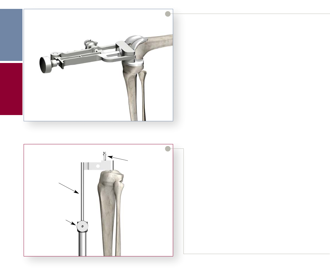
Figure 33
Figure 34
Femoral Trial Assessment
> Assemble the appropriate size and side (Left/Right)
PS or CR Femoral Trial to the Femoral Impactor/
Extractor.
> Impact the PS or CR Femoral Trial onto the
prepared distal femur ensuring the Femoral trial is
aligned with the distal plane.
> Remove the Femoral Impactor/Extractor and assess
the fit of the PS or CR Femoral Trial. Care must be
taken to ensure that all of the osteophytes beyond
the end of the posterior femoral condyles are
removed.
• Cruciate Retaining Knee: Attach the 1/4" Peg
Drill to the Universal Driver and create the
Femoral Distal Fixation Peg holes if using the
Pegless Trials. Use a 1/8" drill for size 3 and 4
femoral Trial. Option: After removing size 3
or 4 Femoral Trial, follow-up with 1/4 in Peg
Drill.
• Posterior Stabilized Knee: If the Peg Holes
were not prepared by using the Pegged Notch
Block, attach the 1/4" Peg Drill to the Universal
Driver and create the Femoral Distal Fixation
Peg holes. Use a 1/8" drill for size 3 and 4
femoral Trial. Option: After removing size 3
or 4 Femoral Trial, follow-up with 1/4" Peg
Drill.
12
Tibial Preparation
Option 1: Extramedullary Technique
> With the knee flexed, place the External Tibial
Alignment Guide on the tibial shaft. Place the
spring-loaded clamp around the distal tibia just
above the malleoli.
> Place the head of the Proximal Rod over the tibial
eminence. There should be a finger’s breadth clearance
between the proximal shaft of the alignment guide and
the anterior cortex when the head is positioned
properly. Center the proximal fixation pins over the
tibial eminence and tap in the most posterior pin first
to fix the anterior/posterior location of the head.
> Rotation is now adjusted, and then set, by anchoring
the second pin. Tighten the vertical screw to secure the
proximal shaft of the guide (Figure 34).
Femoral
Preparation
Tibial
Preparation
Scorpio NRG
PR Single Radius Primary Knee System
Surgical Protocol
Proximal Shaft
Fixation Pin
Vertic a l Screw

13
Figure 35
Figure 36
Figure 37
> Axial alignment is achieved when the vertical
shaft of the instrument parallels the long axis of
the tibia in both the anterior/posterior and
medial/lateral adjustment thumbscrews to
facilitate alignment (Figures 35 and 36).
> Landmarks often used to obtain correct axial
alignment and rotation include:
1. Tibial Tubercle – The alignment rod usually
lies over the medial third of the tibial tubercle.
2. Second Metatarsal – The second metatarsal
generally is in line with the center of the ankle
(Figure 37).
Femoral
Preparation
External Tibial
Alignment Guide
Medial/Lateral
Adjustment Screw
Anterior/Posterior
Adjustment Screw
External Tibial
Alignment Guide
Distal
Alignment
Tibial
Preparation

Figure 38
Figure 39
Figure 40
> Once axial alignment is established, tighten the
anterior/posterior and medial/lateral adjustment
thumbscrews (Figure 38).
14
Tibial Resection Level
> The XcelerateSystem offers Right and Left, 0° and 5°
Tibial Resection Guides.
Note:
0 degrees of posterior slope is recommended for use
with the Scorpio PS femoral components.
5 degrees of posterior slope is recommended for use
with the Scorpio CR femoral components.
> Assemble the tibial stylus onto the Tibial Resection
Guide by depressing the button on the top of the
Tibial Stylus, inserting the stylus into either the medial
or lateral holes on the top of the Tibial Resection
Guide and releasing the button to lock the stylus into
place (Figure 39).
> Attach the Tibial Resection Guide/Tibial Stylus
assembly to the External Tibial Alignment Guide by
sliding it over the top of the proximal shaft, adjusting
the stylus to reference the desired point on the tibial
plateau (Figure 40).
Note: The components shall be positioned to avoid
excessive hyperextension. Excessive femoral flexion and
tibial slope should be avoided when implanting the
components. Implant positioning resulting in excessive
hyperextension may result in premature wear and
damage to the implant.
Tibial
Preparation
Scorpio NRG
PR Single Radius Primary Knee System
Surgical Protocol
Rotational Alignment
Anterior Posterior
Adjustment Screw
Medial/Lateral
Adjustment Screw
Tibial Stylus
Locking Button
Tibial Resection
Guide
Proximal
Shaft
External Tibial
Alignment Guide

15
Figure 41
Figure 42
Figure 43
> The Xcelerate System offers two Tibial styli each
having two resection levels; 2mm and 8mm.
> The settings allow for a corresponding resection
of bone below the point of the stylus (i.e. the
2mm setting allows for a 2mm resection below
the point of the stylus). (Figures 41 and 42).
> Once the resection level is established, tighten
the thumbscrew on the Tibial Resection
Guide. The Tibial Stylus is removed by
depressing the button and pulling it out.
Proximal Tibial Resection
> Secure the Tibial Resection Guide to the proximal
tibia using two 1/8" drill pins, drilling through the
“0” holes.
> Loosen the thumbscrew that holds the Tibial
Resection Guide to the External Tibial Alignment
Guide.
> Loosen the vertical adjustment thumbscrew on the
shaft of the alignment guide.
> Using the Slaphammer, extract the two headed
fixation pins on the top of the alignment guide
from the proximal tibia.
> Remove the proximal shaft of the alignment guide by
sliding it up through the top of the resection guide
(Figure 43).
Tibial
Preparation
Tibial Stylus
Tibial
Resection
Guide
2mm Resection
External Tibial
Alignment Guide
Tibial Stylus
8mm Resection
Tibial
Resection
Guide
External Tibial
Alignment Guide
Tibial
Resection
Guide
Slide Proximal Shaft
up through
Resection Guide
Ver ti c al
Thumbscrew
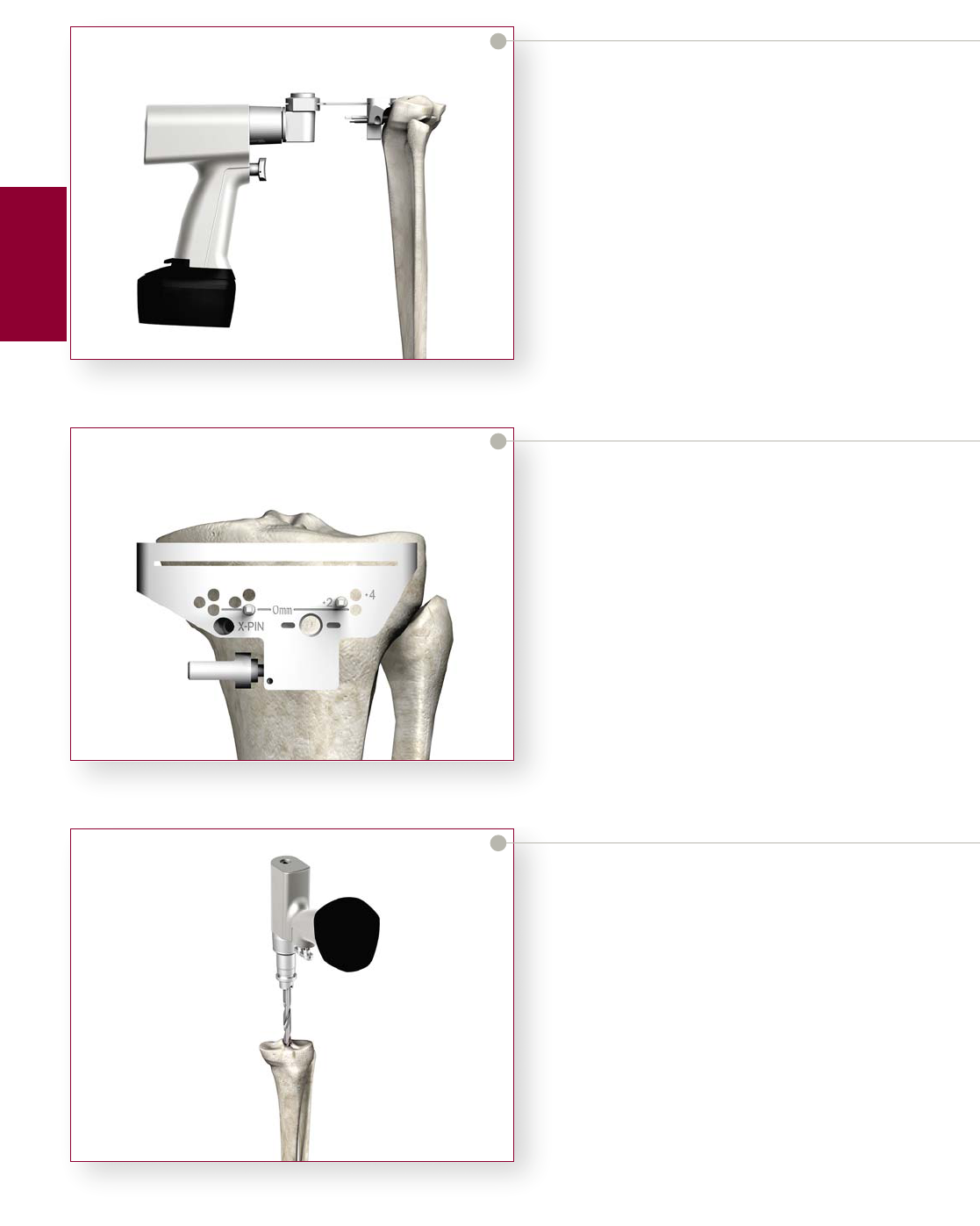
Figure 44
Figure 45
Figure 46
> Slide the Tibial Resection Guide posteriorly until it
comes in contact with the anterior tibia.
> Placing a 1/8" drill pin through the “X” pin hole will
further secure the resection guide to the tibia.
> The Alignment Handle may be used with an
Alignment Rod, referencing the same landmarks as
outlined previously to verify proper alignment.
> Resect the plateau using a 0.05" (1.27mm) saw blade
(Figure 44).
16
> If desired, 2mm or 4mm of additional bone
may be resected by repositioning the guide over the
pins through the +2 or +4 holes respectively
(Figure 45).
> The Tibial Resection Guide is removed by first
sliding the guide off the two 1/8" drill pins and then
removing the pins with the Pin Puller.
Note: If the “X” Pin hole is used, this pin must be
removed prior to repositioning or removing the Tibial
Resection Guide.
Option 2: Intramedullary Technique
IM Rod Placement
> If the tibial eminence is pronounced, make
an initial cut to flatten the tibial plateau and
expose an area of cancellous bone. A 5/16"
hole is drilled in the location determined by
pre-operative X-rays (Figure 46).
> Attach the pre-determined diameter IM Rod (1/4",
3/8", or 5/16") to the T-Handle by depressing the
button to lock into place. Pre-operative X-Ray
templating will aid in the determination of the
IM Rod diameter.
Tibial
Preparation
Scorpio NRG
PR Single Radius Primary Knee System
Surgical Protocol

17
Figure 47
Figure 48
Figure 49
> Introduce the IM Rod into the entry hole and
gradually advance it down the intramedullary canal
(Figure 47). Several steps may be taken to avoid
an increase in intramedullary pressure.
A. Advance the IM Rod slowly.
B. Rotate the IM Rod within the canal during
advancement.
C. Apply suction to the fitting on the end of the
cannulated IM Rod.
> The proximal portion of both the 1/4" and 3/8"
diameter IM Rods changes to 5/16" in diameter.
It is necessary to insert those rods so that the
diameter transition point is within the
intramedullary canal. The 5/16" diameter IM Rod
may be inserted to any depth up to the scribe
mark on the proximal shaft. Once the IM Rod is
positioned, remove the T-Handle (Figure 48).
> Intra-operative X-rays may be obtained to
confirm accurate position of the rod in the canal.
> Slide the IM Alignment Guide over the Alignment
Rod (Figure 49).
Tibial
Preparation
IM Rod
T- Handle
Diameter
Transition
Point
Headed Nail
IM Alignment Jig
IM Rod

Figure 50
Figure 51
Figure 52
Rotation and Varus/Valgus Alignment
> With the body of the IM jig resting on the
proximal tibia, correct rotational alignment is
achieved by rotating the instrument about the
IM rod so that the tibial tubercle appears
slightly lateral to the vertical mounting bar.
The headed nail is impacted, fixing rotational
alignment (Figure 50).
18
> Assemble the appropriate Tibial Resection Guide to
the IM Tibial Alignment Guide by sliding the Tibial
Resection Guide onto the rail of the alignment guide
and tightening the thumbscrew on the resection
guide (Figure 51).
> Attach the alignment handle to the resection guide,
and slide a long alignment rod into the alignment
handle. When correct varus/valgus alignment is
attained, the pin should be centered over the ankle
(Figure 52).
Tibial
Preparation
Scorpio NRG
PR Single Radius Primary Knee System
Surgical Protocol
Mounting Bar
Headed Nail
Thumbscrew
Tibial Resection
Guide
IM Tibial
Alignment Guide
External
Alignment
Rod

19
Figure 53
Figure 54
Figure 55
> If varus/valgus adjustment is needed, Locking Knob
“1” is loosened. The mounting bar is pulled toward
the surgeon, and the jig is rotated until proper
varus/valgus orientation is achieved (Figure 53).
Once the alignment rod is centered over the ankle,
the Locking Knob is securely tightened.
Flexion/Extension Alignment
> If additional posterior slope is required, loosen
Locking Knob “2” and set the slope. Once the
correct slope is attained, securely tighten Locking
Knob “2” to set the final position of the jig
(Figure 54).
> Increment markings have been added to the posterior
slope adjustment FOR REFERENCE ONLY. Bear in
mind that these are reference marks only and not
indicative of an exact measurement of the posterior
slope of the tibial resection. The true slope is
dependent on many factors, including, but not
limited to, tibial anatomy, the placement of the IM
Rod, the position of the cutting block from the
anterior portion of the tibia.
Tibial Resection Level
> The Xcelerate System offers Right and Left, 0° and 5°
Tibial Resection Guides.
Note:
0 degrees of posterior slope is recommended for use
with the Scorpio PS femoral components.
5 degrees of posterior slope is recommended for use
with the Scorpio CR femoral components.
> Assemble the Tibial Stylus onto the Tibial Resection
Guide by depressing the button on the top of the
Tibial Stylus, inserting the stylus into either the
medial or lateral hole on the top of the Tibial
Resection Guide, and releasing the button to lock
the stylus into place (Figure 55).
Note: The components shall be positioned to avoid
excessive hyperextension. Excessive femoral flexion and
tibial slope should be avoided when implanting the
components. Implant positioning resulting in excessive
hyperextension may result in premature wear and
damage to the implant.
Tibial
Preparation
Alignment
Handle
Alignment
Rod
Locking
Knob “1”
Locking
Knob “2”
Tibial
Resection
Guide
Thumbscrew
Tibial
Stylus
Locking
Button

Figure 56
Figure 57
Figure 58
> Loosen the thumbscrew and position the Tibial
Stylus to reference the desired point on the tibial
plateau. Secure the IM Tibial Alignment Guide to
the Tibial IM Rod by re-tightening the thumb-
screw.
> The Xcelerate System offers two Tibial styli each
having two resection levels; 2mm and 8mm.
20
> The settings allow for corresponding resection of
bone below the point of the stylus (i.e. the 2mm
setting allows for a 2mm resection below the point
of the stylus) (Figures 56 and 57).
Proximal Tibial Resection
> Once the resection level is established, secure the
Tibial Resection Guide to the anterior tibia using the
1/8" drill pins, drilling through the “0” holes. Pinning
through the “X” Pin hole will further secure the
Tibial Resection Guide to the tibia (Figure 58).
Tibial
Preparation
Scorpio NRG
PR Single Radius Primary Knee System
Surgical Protocol
IM Tibial
Alignment
Guide
Locking
Screw
2mm Resection Level
Tibial
Resection
Guide
Thumbscrew
Tibial
Stylus
IM Tibial
Alignment
Guide
Locking
Screw
Tibial
Resection
Guide
Thumbscrew
Tibial
Stylus
8mm Resection Level
Tibial Stylus
IM Tibial
Alignment
Guide
1/8" Drill Pin
Tibial
Resection
Guide

21
Figure 59
Figure 60
> Remove the Tibial Stylus by depressing the button
and pulling the stylus out.
> Release the IM Tibial Alignment Guide from the
Tibial Resection Guide by loosening the thumbscrew
on the resection guide. Re-attach the T-Handle to the
IM Rod and extract both the IM Rod and IM Tibial
Alignment Guide together, leaving the Tibial
Resection Guide pinned in place. Resect the tibial
plateau through the slot in the Tibial Resection
Guide. Use of a 0.05" (1.27mm) sawblade is
recommended for an accurate resection (Figure 59).
> Additional bone may be resected by repositioning the
Tibial Resection Guide over the pins in the +2 or +4
holes to resect an additional 2mm or 4mm of bone
respectively (Figure 60).
> The Tibial Resection Guide is removed by first
sliding the guide off the two 1/8" drill pins and then
removing the pins with the Pin Puller.
Note: If the “X” Pin hole is used, this pin must be
removed prior to repositioning or removing the Tibial
Resection Guide.
Tibial
Preparation
Tibial
Resection
Guide
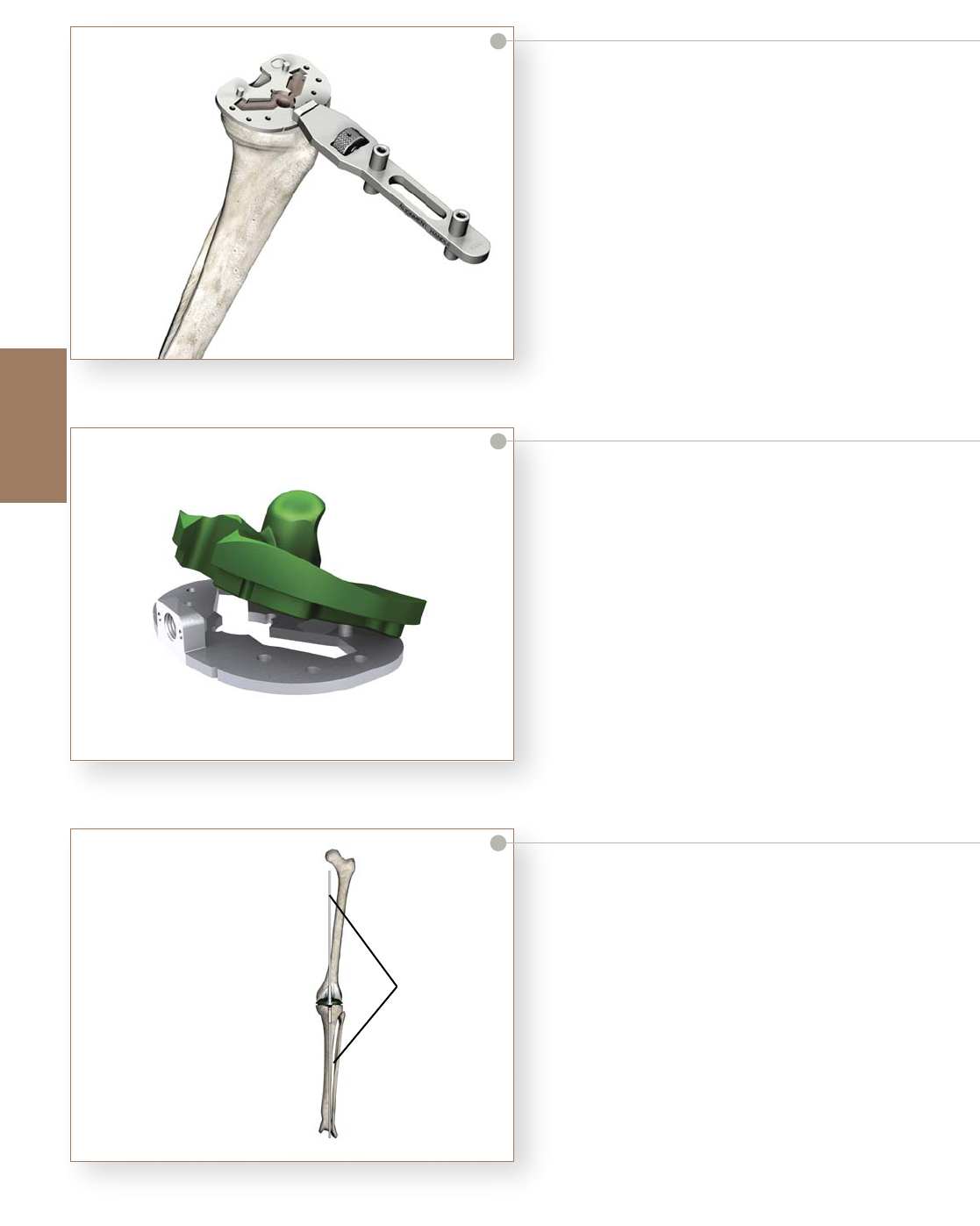
Figure 61
Figure 62
Figure 63
Tibial Baseplate Preparation
Scorpio NRG Tibial Component Sizing
> Maximally flex the knee and deliver the tibia forward.
Assemble a Tibial Trial Baseplate onto the Alignment
Handle and place it on the resected tibial plateau
(Figure 61). Choose the size that best covers the
tibial plateau.
22
Tibial Component Alignment
> Replace the Trial Femoral Component on the femur.
Assemble a Tibial Bearing Insert Trial to the Tibial
Trial Baseplate by first positioning it posteriorly on
the baseplate and then fully seating it anteriorly
(Figure 62). Reverse the steps to dis-assemble the
insert trial from the baseplate.
> Position the assembled insert and baseplate on the
tibial plateau and carry out a trial reduction. Assess
overall component fit, ligament stability, and joint
range of motion.
> As the joint is taken through flexion and extension,
the femoral trial component helps position the tibial
baseplate. Final position of the tibial trial is achieved
when tibiofemoral articular contact is most congruent.
This is best assessed when the knee is in extension.
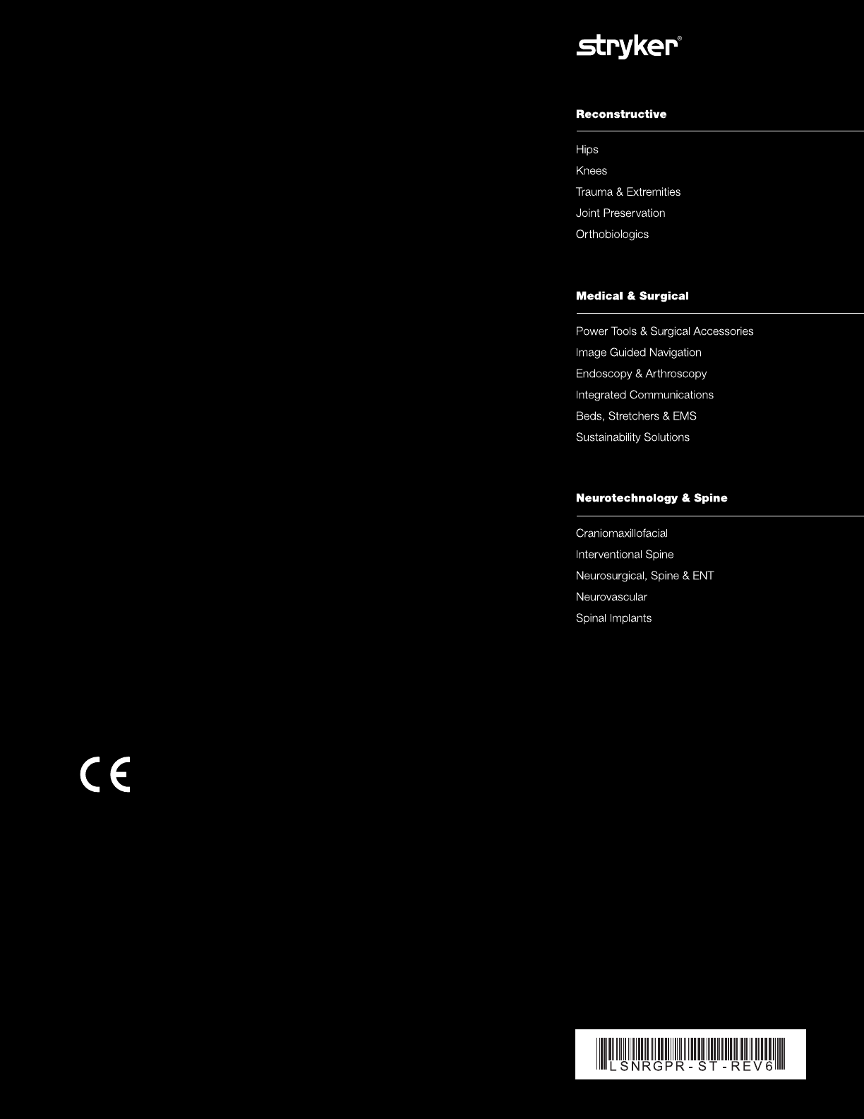
> Overall leg alignment may be assessed at this time.
Re-attach the Alignment Handle to the trial baseplate
and insert two Alignment Rods into the handle. The
rods should parallel the mechanical axis of the leg in
both the coronal (A/P) and sagittal (M/L) views
(Figure 63).
Tibial Baseplate
Preparation
Scorpio NRG
PR Single Radius Primary Knee System
Surgical Protocol
Alignment
Rod
Alignment parallels
the mechanical axis
Tibia Components In Place

23
Figure 64
Figure 65
> Once satisfactory alignment and tibial component
orientation is achieved, mark the anterior tibial
cortex in line with the reference marks on the
anterior border of the trial baseplate (Figure 64).
> Remove the trial components and dis-assemble the
trial insert from the baseplate. Reposition the Tibial
Trial Baseplate aligning the anterior reference marks
on the baseplate with the reference marks on the
anterior cortex. The baseplate is positioned flush to
the anterior tibial cortex.
> Pin the baseplate to the tibial plateau by placing two
short, headed fixation pins through a medial and lateral
hole in the baseplate (Figure 65). Pin hole selection is
not critical; however, if the anterior holes are used and
the pins are fully seated, the Tibial Bearing Insert Trial
may be re-assembled to the pinned baseplate for any
subsequent trial reductions.
Tibial Baseplate
Preparation
Baseplate Reference
Marks
Marker
Short Headed Pins
Tibial Trial
Baseplate

> Advance the punch until it seats fully on the
baseplate (Figure 68). During extraction, take care to
avoid toggle or angulation of the punch as this may
distort the bone preparation. The Quick Release
Slaphammer connects to the punches for extraction.
Figure 66
Figure 67
Figure 68
Tibial Keel Punching
> Tibial Punches are identified by keel size (3/5, 7/9,
11/13) and bone preparation (“Cement Keel”
creates an interference fit around the keel).
> The sequence of steps necessary to prepare the tibia
for the Deltafit Keel may vary depending on the bone
quality of the proximal tibia. In relatively soft bone
(i.e., rheumatoid) only one punching step with the
final tibia size/preparation punch may be required. In
normal bone, it is recommended that a smaller “Press
Fit Keel” punch be used first, followed by the final
size/preparation punch.
> In denser bone, several intermediate punching steps
may be required prior to final punching. If sequential
punching is undertaken, only “Press Fit Punches”
should be utilized until the final size is reached. If
extremely dense bone is encountered, a 3/8" Guide
Bushing may be assembled to the baseplate and a
pilot hole drilled prior to tibial punching (Figure 66).
24
> Assemble the Tibial Punch Tower to the baseplate by
placing the tower onto the two small locating pins on
top of the baseplate. During the subsequent tibial
punching, the tower will maintain correct position of
the punches.
> Fit the appropriate Tibial Punch into the Tibial
Punch Tower (Figure 67). See Appendix 1 - Baseplate
Preparation Table. Handles may be assembled to the
tower to aid in maintaining position and stability of
the tower/baseplate assembly during punching. A
mallet may be used to impact the punch.
Tibial Baseplate
Preparation
Patella
Preparation
Scorpio NRG
PR Single Radius Primary Knee System
Surgical Protocol
Preparation of pilot drill
hole will guide bushing
Tibial Punch
Tibial
Punch
To we r
Quick
Release
Handles
Tibial Punch
is Fully Seated

25
Figure 69
Figure 70
Figure 71
> Once the final punch has been seated, tibial
preparation is complete (Figure 69).
Patella Preparation
> Remove all osteophytes and synovial insertions
around the patella, and measure thickness using a
caliper. After determining the depth of the cut with
a caliper, fix the stylus in the appropriate slot to the
patellar resection guide, and capture the patella
between the jaws of the saw guide. Using a 0.05"
(1.27mm) non-offset sawblade, resect the patella
(Figure 70).
Patella Trial Assessment
> Remove any residual cartilage and wash away all
debris. Place correct size Patella Trial onto the
prepared patella.
> Replace all Trials and assess patellar tracking by
taking the knee through a ROM. The patella should
track normally through the ROM without tendency
for tilting or lateral subluxation.
> Center the chosen patellar drill guide over the patella
with the handle perpendicular to the trochlear
groove. Drill three fixation holes with the appropriate
stepped drill (Figure 71).
> Prepare the resected bone surfaces for bone cement
application. See page 29 for cementing with the
Patellar Clamp.
Tibial Baseplate
Preparation
Patella
Preparation
Completed Tibial Preparation
Patellar
Resection
Guide
Stylus
Stepped Drill
Drill Guide
12 inch
5 or 7

Figure 72
Figure 73
Figure 74
Implantation
Tibial Component
> If tibial fixation is to be augmented by bone screws,
remove the polyethylene plugs in the tibial tray screw
holes prior to implantation (Figure 72).
26
> Assemble the Tibial Component Impactor/Extractor
to the implant. To assemble, retract the slide rod
levers and insert the “feet” into the central hole in the
tibial tray. Release the levers and tighten the knurled
thumbscrew by hand to securely engage the
Impactor/Extractor to the implant (Figure 73).
> Introduce the tibial tray into the prepared tibia and
impact it until the tray is fully seated (Figure 74).
Remove the instrument from the tray before
polymerization. Clear all excess bone cement without
disturbing the position of the implant.
Implantation
Scorpio NRG
PR Single Radius Primary Knee System
Surgical Protocol
Thumbscrew
Slide Lever
Retract side levers to
engage feet in tibial tray
Tibial Tray
Implantation

27
Figure 75
Figure 76
Figure 77
Tibial Bearing Insert Assembly
> Prior to assembly of the prosthetic UHMWPE
bearing insert, the trial insert may be placed in the
tibial tray to once more assess joint stability and
range of motion.
> To assemble the prosthetic bearing insert, distract
the joint and angle the insert posteriorly into the tray.
The posterior lips of the bearing insert must fit
beneath the lips on the interior, posterior tray wall.
> Snap the insert in place anteriorly (Figure 75). Hand
pressure or a light tap with a mallet is required. The
tibial bearing insert is fully seated once the metal
retaining wire locks under the barbs on the anterior,
interior surface of the wall.
Implantation of Femoral Component
> Assemble the appropriate size of left or right femoral
implant onto the Femoral Impactor/Extractor in the
same manner as the femoral trial. See Appendix 2
for Scorpio NRG PS/CR interchangeability chart.
Place the implant on the prepared femur and impact
it until fully seated (Figure 76). The Impactor/
Extractor maintains accurate position of the implant
during implantation.
Note: The components shall be positioned to avoid
excessive hyperextension. Excessive femoral flexion and
tibial slope should be avoided when implanting the
components. Implant positioning resulting in excessive
hyperextension may result in premature wear and
damage to the implant.
Implantation of the Patellar Component
> The back surface of the implant (including the
pocket) and the cut surface of the patella are covered
with a layer of cement. Cement should be interdigitated
into the fixation holes on the cut patella and the pocket
on the back of the all-plastic Patellae Components.
> The patellar clamp locks in place while the cement
hardens (Figure 77).
Closure
> After cement polymerization, thoroughly irrigate the
joint and place suction drains. Hemostasis is achieved
after deflation of the tourniquet. Close soft tissues in
the normal layered fashion.
Implantation
Tibial bearing
Insert
First engage
posteriorly then
snap into place
anteriorly
Femoral Impactor
Patellar Clamp

28
Appendix 1
Scorpio NRG
PR Single Radius Primary Knee System
Surgical Protocol
Appendix 1
3 Press-Fit #3/#5
Press-Fit #3/#5
Cement #3/#5
4 Press-Fit #3/#5
Press-Fit #3/#5
Cement #3/#5
5 Press-Fit #3/#5
Press-Fit #3/#5
Cement #3/#5
6 Press-Fit #3/#5
Press-Fit #3/#5
Cement #3/#5
7
Press-Fit #3/#5
Press-Fit #7/#9
Press-Fit #3/#5
Press-Fit #7/#9
Cement #7/#9
9
Press-Fit #3/#5
Press-Fit #7/#9
Press-Fit #3/#5
Press-Fit #7/#9
Cement #7/#9
11
Press-Fit #3/#5
Press-Fit #7/#9
Press-Fit #11/#13
Press-Fit #3/#5
Press-Fit #7/#9
Press-Fit #11/#13
Cement #11/#13
13
Press-Fit #3/#5
Press-Fit #7/#9
Press-Fit #11/#13
Press-Fit #3/#5
Press-Fit #7/#9
Press-Fit #11/#13
Cement #11/#13
Implant Size Press-Fit Keel Cement Keel
Scorpio NRG Tibial Punching Sequence

29
Appendix 2
Appendix 2
Tibial Tibial IC Notch
Component Tray Punch (mm)
Femoral Tibial Tibial PS Notch &
Component Tray Insert Compactor
Scorpio NRG Sizing Guide
3
3, 4 3 3/5
5, 6 5 3/5
4
3, 4 3 3/5
5, 6 5 3/5
5
3, 4 3 3/5
5, 6 5 3/5
7 7 3/5
6
5, 6 5 7/9
7 7 7/9
7
5, 6 5 7/9
7 7 7/9
9 9 7/9
8
7 7 7/9
9 9 7/9
9
7 7 7/9
9 9 7/9
11, 13 11 7/9
11
9 9 11/13
11, 13 11 11/13
13 11, 13 11 11/13
3 3/5 18
4 3/5 18
5 3/5 18
6 3/5 20.1
7 7/9 20.1
9 7/9 20.1
11 11/13 22.3
13 11/13 22.3

30
Appendix 3
Scorpio NRG
PR Single Radius Primary Knee System
Surgical Protocol
Catalog # Catalog # Catalog # Catalog # Catalog # Thickness
Size #3 Size #5 Size #7 Size #9 Size #11
Scorpio NRG PS Tibial Insert - N2Vac
82-3-0308 82-3-0508 82-3-0708 82-3-0908 82-3-1108 8mm
82-3-0310 82-3-0510 82-3-0710 82-3-0910 82-3-1110 10mm
82-3-0312 82-3-0512 82-3-0712 82-3-0912 82-3-1112 12mm
82-3-0315 82-3-0515 82-3-0715 82-3-0915 82-3-1115 15mm
82-3-0318 82-3-0518 82-3-0718 82-3-0918 82-3-1118 18mm
82-3-0321 82-3-0521 82-3-0721 82-3-0921 82-3-1121 21mm
82-3-0324 82-3-0524 82-3-0724 82-3-0924 82-3-1124 24mm
Appendix 3
81-4403L 81-4403R #3 51mm 57mm 35mm
Non-LFIT
Waf f le
w/Lugs
81-4404L 81-4404R #4 54mm 60mm 37mm
81-4405L 81-4405R #5 56mm 62mm 39mm
81-4406L 81-4406R #6 58mm 65mm 42mm
81-4407L 81-4407R #7 61mm 67mm 44mm
81-4408L 81-4408R #8 63mm 70mm 46mm
81-4409L 81-4409R #9 65mm 72mm 49mm
81-4411L 81-4411R #11 70mm 77mm 53mm
81-4413L 81-4413R #13 75mm 82mm 58mm
Catalog # Catalog # Size A/P M/L Resected
Left Knee Right Knee A/P
Scorpio NRG PS Femoral Component
A/P
M/L
Resected
A/P
Catalog # Catalog # Catalog # Catalog # Catalog # Thickness
Size #3 Size #5 Size #7 Size #9 Size #11
Scorpio NRG PS Tibial Insert - X3
82-7-0308 82-7-0508 82-7-0708 82-7-0908 82-7-1108 8mm
82-7-0310 82-7-0510 82-7-0710 82-7-0910 82-7-1110 10mm
82-7-0312 82-7-0512 82-7-0712 82-7-0912 82-7-1112 12mm
82-7-0315 82-7-0515 82-7-0715 82-7-0915 82-7-1115 15mm
82-7-0318 82-7-0518 82-7-0718 82-7-0918 82-7-1118 18mm
82-7-0321 82-7-0521 82-7-0721 82-7-0921 82-7-1121 21mm
82-7-0324 82-7-0524 82-7-0724 82-7-0924 82-7-1124 24mm

31
Appendix 4
Appendix 4
Catalog # Catalog # Catalog # Catalog # Catalog # Thickness
Size #3 Size #5 Size #7 Size #9 Size #11
Catalog # Catalog # Size A/P M/L Resected
Left Knee Right Knee A/P
Scorpio NRG CR Femoral Component
80-4403L 80-4403R #3 51mm 57mm 35mm
Non-LFIT
Waf f le
w/Lugs
80-4404L 80-4404R #4 53mm 60mm 37mm
80-4405L 80-4405R #5 55mm 62mm 39mm
80-4406L 80-4406R #6 57mm 65mm 42mm
80-4407L 80-4407R #7 60mm 67mm 44mm
80-4408L 80-4408R #8 62mm 70mm 46mm
80-4409L 80-4409R #9 64mm 72mm 49mm
80-4411L 80-4411R #11 69mm 77mm 53mm
80-4413L 80-4413R #13 74mm 82mm 58mm
Scorpio NRG CR Tibial Insert - N2Vac
82-2-0308 82-2-0508 82-2-0708 82-2-0908 82-2-1108 8mm
82-2-0310 82-2-0510 82-2-0710 82-2-0910 82-2-1110 10mm
82-2-0312 82-2-0512 82-2-0712 82-2-0912 82-2-1112 12mm
82-2-0315 82-2-0515 82-2-0715 82-2-0915 82-2-1115 15mm
82-2-0318 82-2-0518 82-2-0718 82-2-0918 82-2-1118 18mm
82-2-0321 82-2-0521 82-2-0721 82-2-0921 82-2-1121 21mm
82-2-0324 82-2-0524 82-2-0724 82-2-0924 82-2-1124 24mm
M/L
A/P
Resected
A/P
Catalog # Catalog # Catalog # Catalog # Catalog # Thickness
Size #3 Size #5 Size #7 Size #9 Size #11
Scorpio NRG CR Tibial Insert - X3
82-6-0308 82-6-0508 82-6-0708 82-6-0908 82-6-1108 8mm
82-6-0310 82-6-0510 82-6-0710 82-6-0910 82-6-1110 10mm
82-6-0312 82-6-0512 82-6-0712 82-6-0912 82-6-1112 12mm
82-6-0315 82-6-0515 82-6-0715 82-6-0915 82-6-1115 15mm
82-6-0318 82-6-0518 82-6-0718 82-6-0918 82-6-1118 18mm
82-6-0321 82-6-0521 82-6-0721 82-6-0921 82-6-1121 21mm
82-6-0324 82-6-0524 82-6-0724 82-6-0924 82-6-1124 24mm

32
Appendix 5
Appendix
Scorpio NRG
PR Single Radius Primary Knee System
Surgical Protocol
Deltafit Series Deltafit Series Deltafit Series Size A/P M/L Stem
PA Microstructured 7000 Waffle
with Screw Holes with Screw Holes No Screw Holes
Tibial Component Baseplate
7145-0003 7125-0003 7115-0003 #3 40mm 61mm 30mm
7125-0004 7115-0004 #4 42mm 63mm 30mm
7145-0005 7125-0005 7115-0005 #5 44mm 66mm 30mm
7125-0006 7115-0006 #6 45mm 68mm 30mm
7145-0007 7125-0007 7115-0007 #7 47mm 71mm 35mm
7145-0009 7125-0009 7115-0009 #9 51mm 77mm 35mm
7145-0011 7125-0011 7115-0011 #11 54mm 82mm 40mm
7145-0013 7125-0013 7115-0013 #13 58mm 88mm 40mm
Use screw
2030-6530-1
2030-6535-1
Use screw
2030-6530-1
2030-6535-1
Stem Length
A/P
M/L
Scorpio Scorpio Size S/I* M/L Thickness
Medialized Concentric
Dome Patella Dome Patella
Universal Size Dia. Thickness
Dome
Patella
73-0510 73-2510 #5 32mm 35mm 10mm
73-0710 73-2710 #7 34mm 38mm 10mm
73-0910 73-2910 #9 36mm 41mm 10mm
73-0110 73-2110 #11 38mm 44mm 10mm
73-3308 #3 30mm 8mm
73-3508 #5 32mm 8mm
73-3708 #7
34mm 8mm
73-3710 #7 34mm 10mm
73-3910 #9 36mm 10mm
73-3110 #11 38mm 10mm
Patella Component - N2Vac
Patella Component - N2Vac
Scorpio Scorpio Size S/I* M/L Thickness
Medialized Concentric
Dome Patella Dome Patella
Universal Size Dia. Thickness
Dome
Patella
73-20-0510 73-20-2510 #5 32mm 35mm 10mm
73-20-0710 73-20-2710 #7 34mm 38mm 10mm
73-20-0910 73-20-2910 #9 36mm 41mm 10mm
73-20-0110 73-20-2110 #11 38mm 44mm 10mm
73-20-3308 #3 30mm 8mm
73-20-3508 #5 32mm 8mm
73-20-3708 #7
34mm 8mm
73-20-3710 #7 34mm 10mm
73-20-3910 #9 36mm 10mm
73-20-3110 #11 38mm 10mm
Patella Component - X3
Patella Component - X3
*S/I = Superior/Inferior
33
Indications
• Painful, disabling joint disease of the knee
resulting from: degenerative arthritis,
rheumatoid arthritis or post-traumatic
arthritis.
• Post-traumatic loss of knee joint
configuration and function.
• Moderate varus, valgus, or flexion
deformity in which the ligamentous
structures can be returned to adequate
function and stability.
• Revision of previous unsuccessful knee
replacement or other procedure.
Additional Indications for Posterior
Stabilized Components:
• Ligamentous instability requiring implant
bearing surface geometries with increased
constraint.
• Absent or non-functioning posterior
cruciate ligament.
Contraindications
• Any active or suspected latent infection in
or about the knee joint.
• Any mental or neuromuscular disorder
which would create an unacceptable risk of
prosthesis instability, prosthesis fixation
failure, or complications in post-operative
care.
• Bone stock compromised by disease,
infection or prior implantation, which
cannot provide adequate support and/or
fixation to the prosthesis.
• Skeletal immaturity.
• Severe instability of the knee joint
secondary to the absence of collateral
ligament integrity and function.
• Obesity. An overweight or obese patient can
produce loads on the prosthesis which can
lead to failure of the fixation of the device
or to failure of the device itself.
Warnings and Precautions:
See package insert for warnings, precautions,
adverse effects and other essential product
information.

Scorpio NRG
PR Single Radius Primary Knee System
Surgical Protocol
34
Notes

325 Corporate Drive
Mahwah, NJ 07430
t: 201 831 5000
www.stryker.com
A surgeon must always rely on his or her own professional clinical judgment when deciding whether to use a
particular product when treating a particular patient. Stryker does not dispense medical advice and recommends
that surgeons be trained in the use of any particular product before using it in surgery.
The information presented is intended to demonstrate the breadth of Stryker product offerings. A surgeon must
always refer to the package insert, product label and/or instructions for use before using any Stryker product.
Products may not be available in all markets because product availability is subject to the regulatory and/or
medical practices in individual markets. Please contact your Stryker representative if you have questions about
the availability of Stryker products in your area.
The products listed above are CE marked according to the Medical Device Directive 93/42/EEC. Products may
not be available in all markets because product availability is subject to the regulatory and/or medical practices
in individual markets. Please contact your Stryker representative if you have questions about the availability of
Stryker products in your area.
Stryker Corporation or its divisions or other corporate affiliated entities own, use or have applied for the
following trademarks or service marks: NRG, Scorpio, Stryker, X3, Xcelerate. All other trademarks are
trademarks of their respective owners or holders.
Literature Number: LSNRGPR-ST Rev. 6
MS/GS 4/12
Copyright © 2012 Stryker
Printed in USA
