
User Manual
FL MGUARD DM UNLIMITED
Installation, Configuration and
Usage of the mGuard device man-
ager (mdm)
Version 1.15.x

2024-01-29
PHOENIX CONTACT 111024_en_01
FL MGUARD DM UNLIMITED - Installation, Configuration and Usage of
the mGuard device manager (mdm)
Version 1.15.x
UM EN MDM 1.15
01
—
This User Manual is valid for FL MGUARD DM UNLIMITED 1.15.x when using the following devices
of the mGuard product range (firmware mGuard 5.0 to 10.3.x):
FL MGUARD 4302 / 4305 FL MGUARD RS4000 VPN-M
FL MGUARD 2102 / 2105 FL MGUARD RS2000-B
FL MGUARD 4102 PCI(E) FL MGUARD GT/GT
FL MGUARD RS4000 FL MGUARD CENTERPORT
FL MGUARD RS2000 FL MGUARD DELTA
FL MGUARD RS4004 FL MGUARD SMART2
FL MGUARD RS2005 FL MGUARD PCI(E)4000
TC MGUARD RS4000 3G FL MGUARD RS
TC MGUARD RS2000 3G FL MGUARD PCI 533/266
TC MGUARD RS4000 4G FL MGUARD SMART 533/266
TC MGUARD RS2000 4G mGuard centerport (Innominate)
FL MGUARD RS4000-P mGuard delta (Innominate)
User Manual
Designation:
Revision:
Order No.:

PHOENIX CONTACT
Please observe the following notes
User group of this manual
The use of products described in this manual is oriented exclusively to:
– Qualified electricians or persons instructed by them, who are familiar with applicable
standards and other regulations regarding electrical engineering and, in particular, the
relevant safety concepts.
– Qualified application programmers and software engineers, who are familiar with the
safety concepts of automation technology and applicable standards.
Explanation of symbols used and signal words
How to contact us
Internet Up-to-date information on Phoenix Contact products and our Terms and Conditions can be
found on the Internet at:
phoenixcontact.com
Make sure you always use the latest documentation.
It can be downloaded at:
phoenixcontact.net/products
Subsidiaries If there are any problems that cannot be solved using the documentation, please contact
your Phoenix Contact subsidiary.
Subsidiary contact information is available at phoenixcontact.com
.
Published by PHOENIX CONTACT GmbH & Co. KG
Flachsmarktstraße 8
32825 Blomberg
GERMANY
Should you have any suggestions or recommendations for improvement of the contents and
layout of our manuals, please send your comments to:
This is the safety alert symbol. It is used to alert you to potential personal injury
hazards. Obey all safety measures that follow this symbol to avoid possible in-
jury or death.
There are three different categories of personal injury that are indicated with a
signal word.
DANGER This indicates a hazardous situation which, if not avoided, will re-
sult in death or serious injury.
WARNING This indicates a hazardous situation which, if not avoided, could
result in death or serious injury.
CAUTION This indicates a hazardous situation which, if not avoided, could
result in minor or moderate injury.
This symbol together with the signal word NOTE and the accompanying text
alert the reader to a situation which may cause damage or malfunction to the
device, hardware/software, or surrounding property.
This symbol and the accompanying text provide the reader with additional in-
formation or refer to detailed sources of information.

PHOENIX CONTACT
General terms and conditions of use for technical documentation
Phoenix Contact reserves the right to alter, correct, and/or improve the technical documen-
tation and the products described in the technical documentation at its own discretion and
without giving prior notice, insofar as this is reasonable for the user. The same applies to any
technical changes that serve the purpose of technical progress.
The receipt of technical documentation (in particular user documentation) does not consti-
tute any further duty on the part of Phoenix Contact to furnish information on modifications
to products and/or technical documentation. You are responsible to verify the suitability and
intended use of the products in your specific application, in particular with regard to observ-
ing the applicable standards and regulations. All information made available in the technical
data is supplied without any accompanying guarantee, whether expressly mentioned, im-
plied or tacitly assumed.
In general, the provisions of the current standard Terms and Conditions of Phoenix Contact
apply exclusively, in particular as concerns any warranty liability.
This manual, including all illustrations contained herein, is copyright protected. Any
changes to the contents or the publication of extracts of this document is prohibited.
Phoenix Contact reserves the right to register its own intellectual property rights for the
product identifications of Phoenix Contact products that are used here. Registration of such
intellectual property rights by third parties is prohibited.
Other product identifications may be afforded legal protection, even where they may not be
indicated as such.

111024_en_01 PHOENIX CONTACT 5
Table of Contents
1 Introduction ................................................................................................................................9
1.1 Manage MGUARD devices ................................................................................... 9
2 Installation ................................................................................................................................11
2.1 System requirements (mdm 1.15.0) .................................................................... 11
2.1.1 Microsoft Windows .............................................................................. 11
2.1.2 Ubuntu Linux ........................................................................................ 11
2.1.3 mdm VA ............................................................................................... 11
3 Pre-configurations ....................................................................................................................13
3.1 Pre-configure the mGuard appliances ................................................................. 13
3.2 Pre-configure the HTTPS configuration pull server.............................................. 13
4 mdm server and mdm client .....................................................................................................15
4.1 Starting the mdm server under Ubuntu................................................................ 15
4.2 Using the mdm client with Windows .................................................................... 15
5 mdm client – Overview .............................................................................................................17
5.1 Login ................................................................................................................... 17
5.2 mdm main window............................................................................................... 18
5.2.1 mdm main menu .................................................................................. 19
5.2.2 mdm tool bar ........................................................................................ 22
5.3 Log window ......................................................................................................... 23
5.3.1 Context menu ...................................................................................... 24
5.3.2 Persistent Event Log ............................................................................ 25
5.3.3 Logging events via syslog .................................................................... 26
5.4 Hardware flavors ................................................................................................. 26
5.4.1 FL MGUARD RS2000 .......................................................................... 26
6 mdm client – Configuration tasks .............................................................................................29
6.1 General remarks.................................................................................................. 29
6.1.1 Navigation tree ..................................................................................... 29
6.1.2 Value types of variables ....................................................................... 31
6.1.3 Indication of invalid input ...................................................................... 35
6.1.4 Indication of changed values ............................................................... 36
6.1.5 Indication of “None“ value or exhausted pool ....................................... 37
6.1.6 Modifying mGuard table variables ........................................................ 38
6.1.7 Modifying complex table variables ....................................................... 40
6.1.8 Applying changes to the configuration ................................................. 41
6.2 Default values...................................................................................................... 42
6.2.1 Behavior of changed default values ..................................................... 42
6.2.2 Inheritance of changed default values .................................................. 43
6.3 Configure Devices ............................................................................................... 44
6.3.1 Device overview table .......................................................................... 44
6.3.2 Device context menu ........................................................................... 52
6.3.3 Device properties dialog ...................................................................... 60
6.4 Configure templates ............................................................................................ 65

FL MGUARD DM UNLIMITED 1.15.x
6
PHOENIX CONTACT 111024_en_01
6.4.1 Template overview table ...................................................................... 65
6.4.2 Template context menu ....................................................................... 67
6.4.3 Template properties dialog .................................................................. 69
6.4.4 Template configuration ........................................................................ 73
6.4.5 Working with templates ........................................................................ 74
6.5 Configure pools ................................................................................................... 79
6.5.1 Pool value overview table .................................................................... 79
6.5.2 Pool context menu ............................................................................... 81
6.5.3 Pool properties dialog .......................................................................... 81
6.6 Configure VPN groups......................................................................................... 85
6.6.1 VPN group overview table .................................................................... 85
6.6.2 VPN group context menu ..................................................................... 88
6.6.3 Editing device membership in VPN groups .......................................... 90
6.6.4 VPN group properties dialog (Meshed VPN networks) ........................ 92
6.7 Configure VPN connections ................................................................................ 95
7 mdm client – Management tasks ..............................................................................................99
7.1 Upload configurations to mGuard devices........................................................... 99
7.1.1 Upload methods ................................................................................... 99
7.1.2 Upload time ........................................................................................ 102
7.1.3 Temporary upload password ............................................................. 103
7.1.4 Upload history .................................................................................... 103
7.2 Manage license vouchers and device licenses.................................................. 104
7.2.1 Manage license vouchers .................................................................. 104
7.2.2 Request/generate licenses ................................................................ 104
7.2.3 Manage device licenses .................................................................... 105
7.2.4 Refresh licenses ................................................................................ 106
7.3 Manage users, roles, and permissions .............................................................. 107
7.3.1 Manage users .................................................................................... 108
7.3.2 Manage roles ..................................................................................... 108
7.3.3 Permissions ....................................................................................... 109
7.3.4 User authentication ............................................................................ 110
7.4 Manage X.509 certificates................................................................................. 111
7.4.1 Machine certificates ........................................................................... 111
7.4.2 CA certificates (mGuard firmware 5.0 or later) ................................... 113
7.4.3 Remote certificates (mGuard firmware 5.0 or later) ............................ 113
7.4.4 Connection certificates ...................................................................... 113
7.5 Use X.509 certificates (mGuard firmware 5.0 or later) ....................................... 114
7.6 Manage firmware upgrades with mdm............................................................... 115
7.7 Rollback support................................................................................................ 118
7.8 Redundancy mode ............................................................................................ 118
8 Configuration history ..............................................................................................................119
8.1 The configuration history dialog......................................................................... 119

Table of Contents
111024_en_01 PHOENIX CONTACT 7
8.2 Viewing historic configurations .......................................................................... 123
8.3 Comparison of historic configurations................................................................ 123
8.4 Reconstructing a device from a historic configuration........................................ 125
8.5 Report of changes ............................................................................................. 126
9 Creating and managing certificates ........................................................................................129
9.1 Certificates and keys for SSL ............................................................................ 129
9.2 Certificates and keys for a PKI........................................................................... 134
9.2.1 Create the CA certificates .................................................................. 136
9.2.2 Create the keystores .......................................................................... 145
9.2.3 Requirements for certificates ............................................................. 147
10 Configure mdm server and mdm CA server ...........................................................................149
10.1 mdm server (preferences.xml file) ..................................................................... 149
10.2 mdm Certification Authority (CA) ....................................................................... 157
10.2.1 Overview ............................................................................................ 157
10.2.2 mdm CA server (ca-preferences.xml file) ........................................... 158
11 Glossary .................................................................................................................................163

FL MGUARD DM UNLIMITED 1.15.x
8
PHOENIX CONTACT 111024_en_01

Introduction
111024_en_01 PHOENIX CONTACT 9
1 Introduction
1.1 Manage MGUARD devices
mGuard device manager (mdm) enables the convenient management of mGuard security
appliances. The tool offers a template mechanism that allows to centrally configure and
manage thousands of mGuard devices.
With a click of your mouse you can generate the desired firewall rules, NAT settings, etc.,
and upload the generated configurations to the mGuard devices in the network, deploying
in an instant your desired device configurations.
mdm is a client-server application, the client offering full control of all mdm features, the
server storing the configuration in a database, generating configuration files, and uploading
those files to the devices upon request.
Please read this document for information on the installation of mdm, how to efficiently gen-
erate configurations for and how to upload configurations to your mGuard devices. Also
refer to the release notes of mdm 1.15.x.
Supported firmware
versions
mGuard device manager (mdm) 1.15.x supports the following firmware versions:
– mGuard 8.0 to 9.0 (completely)
– mGuard 10.3.0 (completely)
– mGuard 5.0 to 7.6 (with restrictions)
The firmware mGuardNT is no longer supported.
System requirements: Ubuntu operating system in the mdm VA
mdm 1.15.0 can no longer be installed and operated under Windows, but only under the
operating system Ubuntu 22.04 LTS in the virtual machine "mdm-VA" provided by Phoe-
nix Contact (see Section 2.1).
FL MGUARD 1000 devices are no longer supported
As of mdm 1.15.0, it is no longer possible to manage FL MGUARD 1102/1105 devices.
FL MGUARD 2000/4000 devices are fully supported
With version mdm 1.15.0 it is possible to manage mGuard devices of the FL MGUARD
2000/4000-family with installed firmware version mGuard 10.3 or higher.
Variables that are not available in comparison to devices with installed mGuard 8/9 firm-
ware must be deactivated or reset to the factory settings on the mGuard 8/9 devices be-
fore they can be imported (from an ATV file or a template).
(See also the user manual UM EN FW MGUARD10 - 110191_en_05, available for down-
load at phoenixcontact.com/products
).
The exact procedure for device migration is described in the user manual 111259_en_xx
(AH EN MGUARD MIGRATE 10).

FL MGUARD DM UNLIMITED 1.15.x
10
PHOENIX CONTACT 111024_en_01

Installation
111024_en_01 PHOENIX CONTACT 11
2 Installation
2.1 System requirements (mdm 1.15.0)
2.1.1 Microsoft Windows
For mdm 1.15.0, a version of the “mdm installer for Windows” is no longer provided, so that
mdm 1.15.0 can no longer be installed on a Windows system.
An update to mdm 1.15.0 is likewise not supported on a Windows system.
To be able to continue to run mdm 1.15.x on a Windows system, you can use the virtual ma-
chine „mdm VA“ (VA = Virtual Appliance), provided by Phoenix Contact, running a prein-
stalled Ubuntu operating system (see Section 2.1.3).
2.1.2 Ubuntu Linux
mdm 1.15.0 can only be installed and operated under the Ubuntu 22.04 LTS operating sys-
tem in the virtual machine "mdm VA" provided by Phoenix Contact (see Section 2.1.3).
2.1.3 mdm VA
The virtual machine „mdm VA“ is provided as an OVA file and run using a virtualization soft-
ware program. The mdm VA is preconfigured by means of a configuration file provided by
Phoenix Contact and is an easy way of installing mdm 1.15.x.
Basically, the following steps must be performed to install mdm 1.15.x in a virtual environ-
ment and use it as usual:
1. Download VirtualBox and install it in Windows
2. Download the mdm VA and import it into VirtualBox
3. Download the configuration file and add it to the mdm VA
4. Start the mdm VA and install mdm 1.15.x in the mdm VA
5. Migrate the mdm databases from mdm 1.13.x or 1.14.x to mdm 1.15.x
The installation and operation of mdm 1.15.0 in the virtual machine is described in detail in
the user manual „Using mdm 1.15.x in the mdm VA“ (AH EN MDM VA - 110903_en_01).
(Download at: phoenixcontact.net/product/2981974
.)
System requirements of the mdm VA:
– Memory (RAM): min. 4096 MB
– Hard disk space: min. 10 GB
System requirements mdm client:
– Operating system: Ubuntu / Windows
– Java platform (JRE): OpenJDK 11
– Memory (RAM): 512 MB at least
– Hard disk space: 500 MB at least
– Resolution color monitor: 1280 × 1024 at least

FL MGUARD DM UNLIMITED 1.15.x
12
PHOENIX CONTACT 111024_en_01
Pre-configurations
111024_en_01 PHOENIX CONTACT 13
3 Pre-configurations
3.1 Pre-configure the mGuard appliances
Please follow the steps described in the User Manual “Installing and starting up the mGuard
hardware“, available at: phoenixcontact.net/products
, for starting up and configuring the de-
vice (IP addresses of the interfaces etc.).
Enable SSH access The mdm installs the configuration files on the mGuards using SSH. Therefore SSH has to
be permitted on the mGuards if mdm is using the external (untrusted) interface to upload the
configuration.
Select Management » System Settings » Shell Access in the menu of the Web user inter-
face and enable SSH remote access in the menu Device access. For more detailed infor-
mation on SSH remote access please consult the mGuard Reference Manuals.
3.2 Pre-configure the HTTPS configuration pull server
To transmit information on the configuration status of an mGuard, the HTTPS pull server has
to send SYSLOG messages to the mdm server (pull feedback).
For further information, please refer also to the Software Reference Manual “Configura-
tion of the mGuard security appliances Firmware“, available at: phoenixcontact.net/prod-
ucts.
If you enable remote access, make sure that you change the default admin and root pass-
words to secure passwords.
mdm is using the admin password to log into the mGuard. If the password was changed
locally on the device please change the password setting in mdm accordingly using the
Set Current Device Passwords option in the context menu of the device overview table.
Otherwise mdm is not able to log into the device.
The current root password is part of the configuration file. If the password was changed
locally on the device please change the password setting in mdm accordingly. Otherwise
the mGuard will reject the configuration.
Please make sure that neither the communication between the HTTPS server and the
mdm server nor the communication between the HTTPS pull server and the mGuards is
blocked by a firewall or a NAT device.

FL MGUARD DM UNLIMITED 1.15.x
14
PHOENIX CONTACT 111024_en_01

mdm server and mdm client
111024_en_01 PHOENIX CONTACT 15
4 mdm server and mdm client
4.1
Starting the mdm server under Ubuntu
4.2 Using the mdm client with Windows
Prerequisite
– The Java runtime environment OpenJDK 11 is installed on the Windows system.
– The mdm component mdm-clientdownload is installed in the mdm VA.
To use the mdm client, proceed as follows:
• Make the contents of the file mdm-client.zip available on the desired system:
– For this, connect from there to the mdm web server at the configured IP address:
https://<IP address>/mdm
– The file is offered for download.
– Download the file.
– Unpack the zip file.
• Start the mdm client by double-clicking on the file mdm-client-1.15.0.jar or via the com-
mand line: java -jar mdm-client-1.15.0.jar .
mdm 1.15.0 in the mdm VA (Ubuntu 22.04 LTS)
Start
mdm server sudo systemctl start mdm-server
mdm ca server sudo systemctl start mdm-ca
Stop
mdm server sudo systemctl stop mdm-server
mdm ca server sudo systemctl stop mdm-ca

FL MGUARD DM UNLIMITED 1.15.x
16
PHOENIX CONTACT 111024_en_01
mdm client – Overview
111024_en_01 PHOENIX CONTACT 17
5 mdm client – Overview
The mdm client is the graphical front-end to access all features of mdm. It allows to create
and manage devices, templates, pools, and VPN groups, initiates the upload of configura-
tions to devices or initiates the export of configuration files to the file system.
For information on how to start and stop the client see “mdm server and mdm client” on
page 15.
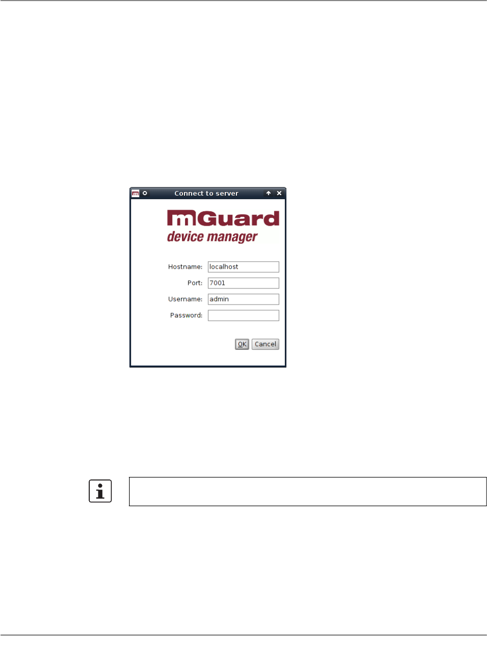
5.1 Login
Before connecting to the server, you have to authenticate yourself in the login-window. The
server IP address/hostname (of the mdm VA) must be entered in the field „Hostname“. Fur-
thermore the server port to be used can be set in the login window.
Figure 5-1 The mdm client login window
There are three predefined user accounts: root, admin and audit. The user root can access
all settings, admin can by default modify all configuration settings and read user manage-
ment settings, whereas audit has read-only permission by default, i.e. the audit user cannot
change any settings, except for his password. The permissions for the users can be
changed, if desired (see “Manage users, roles, and permissions” on page 107). The default
passwords for user admin is admin, the default password for user audit is audit, the default
password for root is root.
Using multiple clients Multiple mdm clients using an mdm server instance concurrently are fully supported only by
the mdm Unlimited Edition. All other available editions still have the limitation to two concur-
rent clients. Entities are locked if this is necessary to prevent two users from editing the
same variable simultaneously. This includes inheritance hierarchies (where a user could
edit a variable that a descent template or device inherits), but not synthesized VPN connec-
tions (which are read-only in the receiving device). If another user tries to open the device
or the template an error message will be displayed. If a client opens a Template properties
dialog, then the template and all devices referencing this template will be locked and cannot
be opened by another user.
It is highly recommended to change the default passwords after installation (please refer
to “Manage users, roles, and permissions” on page 107).
FL MGUARD DM UNLIMITED 1.15.x
18
PHOENIX CONTACT 111024_en_01
The same is true for pools and VPN groups.
In case the connection between a client and a server is interrupted and cannot be termi-
nated gracefully, the device/template/pool/VPN group that was locked by that client will get
released after an inactivity timeout (can be configured in the server configuration, see “mdm
server (preferences.xml file)” on page 149, key maxInactiveInterval), i.e. it could happen
that certain settings cannot be accessed until the inactivity timeout is reached.
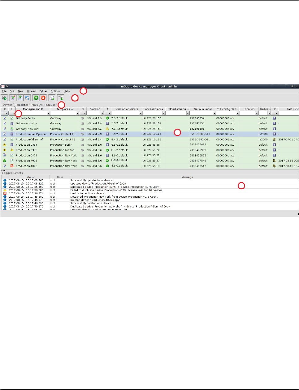
5.2 mdm main window
The following screenshot shows the mdm main window:
Figure 5-2 mdm main window
The mdm main window is divided into a tab area ① to open the device/template/pool/VPN
group overview tables ( e.g. ② ) and a log window ③.
It also contains a tool bar ④ and the main menu ⑤. If enabled, the entries in the different
columns can be filtered by typing any term in the text fields ⑥.
The different sections and their functionality are explained in the following chapters.
2
4
5
1
3
6

mdm client – Overview
111024_en_01 PHOENIX CONTACT 19
5.2.1 mdm main menu
The following entries can be selected in the mdm main menu.
The mdm main menu
File Connect to Server/Dis-
connect from Server
Connects to or disconnects from the server.
Exit Exits the client.
Edit Edit Item Opens the Properties Dialog of the currently selected item (de-
vice, template, pool, or VPN group) in the overview table.
Web Configure Opens the Web GUI for the selected devices in the device ta-
ble.
Cut Cuts the marked text in the currently active table filter field to
the clipboard.
Copy Copies the marked text in the currently active table filter field
to the clipboard.
Paste Pastes the clipboard contents to the currently active table filter
field.
Select All Selects all entries in the currently active overview table.
New Device Creates a new device and opens the Device properties dialog.
Template Creates a new template and opens the Template properties
dialog.
Pool Creates a new pool and opens the Pool properties dialog.
VPN Group Creates a new VPN group and opens the VPN Group Proper-
ties Dialog.
Only active if at least one device in the device
table is selected.
The Accessible via address is required for this
option. It can be configured in the General set-
tings of the Device properties dialog (see
Chapter 6.3.3).

FL MGUARD DM UNLIMITED 1.15.x
20
PHOENIX CONTACT 111024_en_01
Device Import Opens a window that allows to select an import file.
With the device import option, you can import an automatically
(e.g. with a script) generated file of devices. This can be used
to create a large number of devices in mdm without going
through the process of creating them manually.
The import file must be comma-separated value (CSV) for-
matted. Either a comma (,) or a semicolon (;) can be used as
a field separator. Each record (line) in the file describes a sin-
gle device and consists of the following fields:
Field > Description
#0 > Management ID
#1 > Firmware Version
#2 > Template Name
#3 > Reachable via” address
#4 > Serial Number
#5 > Flash ID
#6...#n > Variable assigments
The Management ID and Firmware Version (fields #0 and #1)
are mandatory, all other fields are optional. If a field is empty
or non-existent, the corresponding attribute is not set.
The Firmware Version field must be a supported firmware ver-
sion (without patchlevel) as it would appear in the Version col-
umn of the device overview table, e.g. mGuard 6.1.
The Template Name must either be the name of an existing
template, which is assigned to the new device, or empty, in
which case no template is assigned.
Scalar variables (i.e. variables that store a single value and are
not contained in a table) can be set with an assignment of the
form <VARIABLE_NAME>=<VALUE>.
Example record:
My Device,mGuard 6.1,,192.168.2.3,17X46201,,
ROUTERMODE=router,MY_LOCAL_IP=192.168.2.3
(Please note that the record must be contained in a single
line.)
If a record is not valid, it is skipped and an error message is
logged.
Import X.509 Certifi-
cates
Import certificates created during the manual certificate enroll-
ment process (see “Machine certificates” on page 111 for
more detailed information).
The mdm main menu

mdm client – Overview
111024_en_01 PHOENIX CONTACT 21
Upload For an overview of the configuration upload process and the different upload methods see
“Upload configurations to mGuard devices” on page 99.
Selected Uploads configurations to the devices currently selected in the
device table.
Changed Uploads configurations to the devices with a configuration sta-
tus of out-of-date.
All Uploads configurations to all devices.
Extras Manage Device
Licenses...
Manage your license vouchers and device licenses.
For information on how to manage licenses and vouchers see
“Manage license vouchers and device licenses” on page 104.
Manage License
Vouchers...
Manage Profile Keys Manage your profile keys.
For information on how to manage profile keys see “Manage
Profile Keys” on page 102.
Change Own Pass-
word
Opens a dialog that enables the current user to change the
password.
Manage Users And
Roles
Manage your users and roles.
For information on how to manage users and roles see “Man-
age users, roles, and permissions” on page 107.
Options Default Browser Please specify a command line to be used to start the browser.
The command line should start with the full path and the name
of the binary. Append the string {url}, which will be replaced
with the URL of the mGuard, e.g. on Windows enter:
C:\Program Files\Firefox\Firefox.exe {url}
Default Firmware Ver-
sion
This is the firmware version that will be used when creating a
new device or template.
Disable Filtering The filter in the device, template, pool, and VPN group table
can be switched on and off using this option.
Help About... Shows information about the currently installed mdm version
and included third-party software.
mdm User Manual Opens the mdm User Manual in a web browser (internet con-
nection required).
mdm Server License... Shows the installed mdm license.
The mdm main menu

FL MGUARD DM UNLIMITED 1.15.x
22
PHOENIX CONTACT 111024_en_01
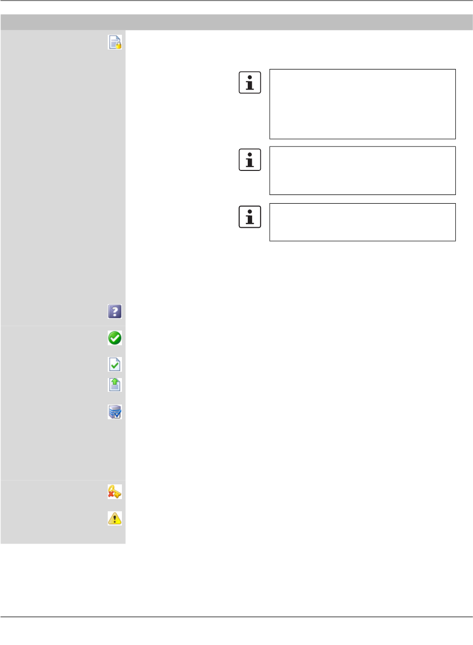
5.2.2 mdm tool bar
The tool bar offers short-cuts to some of the functions in the main menu or the context menu.
The mdm toolbar
No connection to server; if clicked: connect to server.
Connection established; if clicked: disconnect from server.
Edit the selected entry (device, template, pool, or VPN group).
Upload the configuration to the selected devices.
Upload the configuration to the selected devices.
Open the Web GUI of the selected devices in the device table.
Delete the currently selected entries.
Open a dialog to generate/request licenses from the license
server for the selected devices.
Add an entry (device, template, pool, or VPN group) and open
its Properties Dialog.
Filter of the current overview table (device, template, pool, or
VPN group) is active. If clicked: deactivate the filter.
Filter of the current overview table (device, template, pool, or
VPN group) is inactive. If clicked: activate the filter.
mdm client – Overview
111024_en_01 PHOENIX CONTACT 23
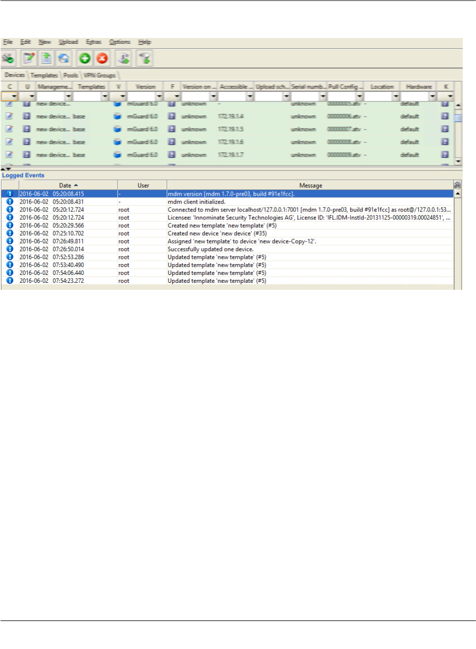
5.3 Log window
The log window shows various events, including the following:
– Upload results.
– Creation, deletion, modification of a device, template, pool, VPN group, user, or role.
– Connect or disconnect of the client.
For each event, the severity, the date and time, the user name, and a message are logged.
If an event is not the result of a user action, “–” is logged instead of the user name. Double-
clicking on a log entry opens a window with detail information.
Sorting the table The header of the table can be used to sort the table entries. A click on a header of a column
will activate the (primary) sort based on this column. This is indicated by the arrow in the col-
umn header. A second click on the same header will reverse the sort order. Clicking on an-
other column header activates the sort based on this new column, the previously activated
column will be used as secondary sorting criterion.

FL MGUARD DM UNLIMITED 1.15.x
24
PHOENIX CONTACT 111024_en_01
5.3.1 Context menu
The context menu is opened by clicking on the log window with the right mouse button.
The following actions can be performed.
Auto-scrolling If a new event is logged, the log window is automatically scrolled so that the new entry is
visible by default. The auto-scrolling mechanism can be disabled and re-enabled by clicking
on the icon in the upper right corner of the log window.
Log window context menu
Show Persistent Event
Log
Opens the Persistent Event Log Window (see “Persistent
Event Log” on page 25).
Clear Deletes the log entries. This applies to the current mdm client
only, i.e. other clients are not affected.
Export Opens a file chooser window and exports the log entries to an
XML file.
Filter Log Entries Enables or disables the filter for the log entry table. If the filter
is enabled, the first row of the table accepts the input of regular
expressions (see Chapter 11, Regular expressions), which
can be used to efficiently filter the table entries.
Increase Verbosity Enables or disables verbose logging. If verbose logging is en-
abled, some events which are not normally useful and may be
confusing are logged.
mdm client – Overview
111024_en_01 PHOENIX CONTACT 25
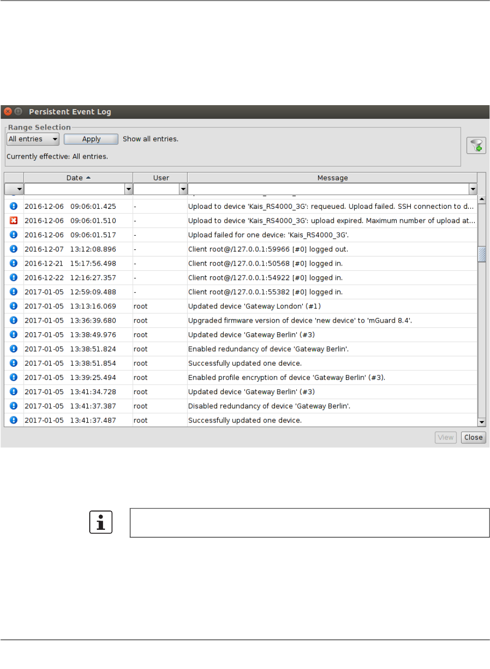
5.3.2 Persistent Event Log
The Persistent Event Log window shows selected events in the same manner as the log
window. Unlike the entries in the log window, the entries in the Persistent Event Log Window
are stored persistently in the mdm database, i.e. they are retained even if the mdm server
is restarted.
The number of days, after which the entries in the database expire (default: 200 days) can
be configured in the file preferences.xml (node event).
Range selection Since there can be a large number of persistent log entries, not all entries are automatically
loaded from the mdm server when the dialog is opened. By changing the criteria in the
Range Selection field and clicking the Apply button, the history entries matching the spec-
ified critera can be loaded.
By default, the latest (i.e. newest) 100 entries are loaded.

FL MGUARD DM UNLIMITED 1.15.x
26
PHOENIX CONTACT 111024_en_01
5.3.3 Logging events via syslog
The same events logged in the persistent event log (see “Persistent Event Log” on
page 25), or a subset selected by the severity, can be sent to a syslog server (see “mdm
server (preferences.xml file)” on page 149).
5.4 Hardware flavors
5.4.1 FL MGUARD RS2000
Most mGuard devices support the same configuration variables, irrespective of their hard-
ware. However, the FL MGUARD RS2000 / TC MGUARD RS2000 3G /
TC MGUARD RS2000 4G / FL MGUARD RS2005 supports only a limited set of variables.
FL MGUARD RS2000 devices (rs2000) can be managed with mdm through its hardware
flavor mechanism.
A device can be set to one of two hardware flavors, default or rs2000
(FL MGUARD RS2000). Setting it to rs2000 has the effect that variables not supported by
this platform are omitted.
The persistent event log
All Entries Loads all log entries.
Time Range Loads all entries which have been created during a time
range. The time range must be specified:
– If a lower bound, but not an upper bound is specified, all
entries newer than the lower bound are loaded.
– If an upper bound, but not a lower bound is specified, all
entries older than the upper bound are loaded.
– If both a lower and an upper bound are specified, all en-
tries created during the time interval given by the bounds
are loaded.
Times are specified as an ISO date (YYYY-MM-DD where
YYYY is the year, MM is the month of the year between 01 and
12, and DD is the day of the month between 01 and 31) option-
ally followed by an ISO time (hh:mm:ss where hh is the hour
according to the 24-hour timekeeping system, mm is the min-
ute and ss is the second). For example, a quarter past 4 p.m.
and 20 seconds on December 22nd, 2010 would be written as
2010-12-22 16:15:20.
Alternatively, click on the icon to select the date from a cal-
ender.
Last Entries Loads the latest (i.e. newest) entries. The number of entries
must be specified.
If the number of entries is large (i.e. thousands
or more), loading all entries may incur a signifi-
cant delay.
Preconditions: Firmware version must be mGuard 7.5 or later, and redundancy must be
disabled.

mdm client – Overview
111024_en_01 PHOENIX CONTACT 27
Templates have no hardware flavor; they always contain all the variables corresponding to
the default flavor. If variables not supported by a device set to the FL MGUARD RS2000
(rs2000) flavor are inherited from a template, such variables are ignored.
Some variables are supported on FL MGUARD RS2000 devices, but have only a limited
range of supported values. If such a variable is inherited by a device set to the
FL MGUARD RS2000 (rs2000) flavor, and the inherited value is not supported, the variable
becomes invalid and must be corrected in the configuration dialog before the device can be
uploaded. The mdm 1.15.x does not support TC MGUARD RS2000 3G/4G and
FL MGUARD RS2005 devices as a separate hardware flavor. The hardware flavor rs2000
(FL MGUARD RS2000) with network mode Router should be used instead.

FL MGUARD DM UNLIMITED 1.15.x
28
PHOENIX CONTACT 111024_en_01
mdm client – Configuration tasks
111024_en_01 PHOENIX CONTACT 29
6 mdm client – Configuration tasks
6.1 General remarks
The Device properties dialog, the Template properties dialog, the Pool Value Properties Di-
alog, and the VPN group properties dialog are used to configure devices, templates, pools,
or VPN groups, respectively. The device and template dialogs are very similar, therefore the
common parts are described in this chapter.
Chapter 6.3.3 and Chapter 6.4.3 discuss the differences between the two dialogs. The pool
configuration is explained in Chapter 6.5.3. For detailed information on the template and in-
heritance concept please refer to Chapter 6.4.5 (Working with templates). The VPN group
configuration is described in Chapter 6.6.4.
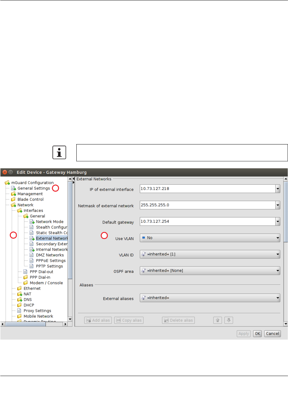
6.1.1 Navigation tree
On the left side of the dialog you can find the navigation tree ①, which resembles the menu
structure of the mGuard Web GUI. Compared to the mGuard GUI the navigation tree con-
tains an additional entry General Settings ②, which contains template and device param-
eters only used in mdm.
For more information on the General Settings please refer to the following chapters.
1
2
3

FL MGUARD DM UNLIMITED 1.15.x
30
PHOENIX CONTACT 111024_en_01
Navigation tree context menu
The navigation tree has a context menu, which can be opened by clicking on the tree with
the right mouse button. The context menu contains various entries to fold/unfold parts of the
tree. Furthermore the context menu shows the key shortcuts to access the menu entries.
mGuard configuration The navigation tree allows you to navigate conveniently to the mGuard variables. If you click
on a “leaf” of the tree, the corresponding mGuard variables and the associated settings are
shown in the right area ③ of the Properties Dialog.
Navigation tree context menu
Focus on Subtree Only the subtree of the selected node will be fully expanded. All other currently expanded
nodes/subtrees will be collapsed.
Collapse All Other Nodes All nodes that are currently not selected will be collapsed.
Scroll to Active Node The node that is currently selected will be focused if it is not already visible.
Collapse Collapse All Nodes All nodes will be collapsed.
Collapse Selected
Subtree
The selected subtree will be collapsed.
Collapse Selected
Node
The selected node will be collapsed.
Currently expanded subtrees of the node will appear ex-
panded again, when the node will be expanded the next time.
Expand Expand All Nodes All nodes will be fully expanded.
Expand Selected Sub-
tree
The selected subtree will be fully expanded.
Expand Selected Node The selected node will be expanded (only one level).
Focus on Here
Defined Nodes
All nodes with values that are not inherited will be expanded
(i.e. value types set to custom or local).
Focus on Inherited
Nodes
All nodes with inherited values will be expanded.
Focus on Incomplete
Nodes
All nodes with inherited “None“ values or unsatisfied pool ref-
erences will be expanded.

mdm client – Configuration tasks
111024_en_01 PHOENIX CONTACT 31
6.1.2 Value types of variables
Depending on the variable, different value types can be selected (exemplarily shown for the
Device properties dialog, see below).
Different value types of variables
Variables with a fixed value
set
Inherited Set the variable to the default value or to the value defined in
an assigned template (if applicable). The usage of templates
and inherited values is further explained in “Template proper-
ties dialog” on page 69 and “Working with templates” on
page 74.
Local The mGuard supports (among others) two roles, the admin
who is able to change all mGuard variables and the netadmin
who is able to change only local variables. The Local value
determines whether a variable is local, i.e. whether or not it
can be managed by the netadmin on the mGuard. If a variable
is local, it will not be managed by mdm anymore in order to
avoid conflicts between mdm and the netadmin.
Fixed values A number of fixed values which can be selected for this vari-
able. The selectable values depend on the variable. In the ex-
ample above (see figure) the fixed values are: Provider de-
fined and User defined for the variable Hostname mode.
Different value types of variables
Variables with an editable
value
Inherited See above.
Local See above.
Custom If you select the Custom value entry, the combo box becomes
editable and you can enter a specific value for the variable,
e.g. prod2975 in the example in the figure above. The value
you entered is subsequentely shown as available selection in
the combo box.

FL MGUARD DM UNLIMITED 1.15.x
32
PHOENIX CONTACT 111024_en_01
Different value types of variables
Table variables (e.g. incom-
ing firewall rules)
Table variables allow the following choices (for more information on tables please see
“Modifying mGuard table variables” on page 38).
Inherited Set the variable to the default rows or to the rows defined in an
assigned template (if applicable). The inherited rows are
shown at the beginning of the table in a different color and are
not editable or selectable. The usage of templates and inher-
ited values is further explained in “Template properties dialog”
on page 69 and “Working with templates” on page 74.
Local See above.
If you set a table variable to Local and mdm shows an error,
please check whether May append is set as permission in the
template (if any). If May append is selected as permission for
the table in the template, it is only allowed to append rows in
the Device properties dialog, therefore the selection of Local
results in an error.
mdm client – Configuration tasks
111024_en_01 PHOENIX CONTACT 33
Custom If you select Custom the table and its associated menu ele-
ments become enabled. Table rows defined in a template
may be copied from the template to the device. They can be
deleted and edited or new rows can be added in the Device
properties dialog (only in certain cases: see described behav-
ior below).
Behavior (only permission setting
May override
):
General case: In general, switching the table from Inherited
to Custom overrides the table completely, i.e. the table con-
tent defined at the template is not retained on the device, but
default table rows are set (e.g. Firewall Outgoing Rules).
Exception: If the table has no default row (i.e. the table is
empty), as a convenience, after switching from Inherited to
Custom the table content inherited from the template is cop-
ied into the Custom table on the device in the form of new
rows (e.g. Firewall Incoming Rules).
Workaround for the general case: For the general case,
there is a possibility of enforcing the copy of the inherited table
rows: set the table as Custom, remove the default row(s), set
the table back to Inherited, and then back again to Custom.
The resulting Custom table will have copied the rows from its
parent template.
Custom + Locally
appendable
(Device properties dialog only)
Basically the same as Custom, but this option allows the user
netadmin on the mGuard to add further rows. (The rows de-
fined in mdm cannot be edited or deleted by the user netadmin
on the mGuard.)
Different value types of variables
Please note that deleting or editing the rows
does not change the rows in the template. You
may also add new rows to the table.
Please note that it is possible to switch between
Custom and the other value types without los-
ing any data. But if you switch from Custom to
e.g. Inherited and then apply your settings and
leave the dialog, all custom rows you entered
will be lost.
FL MGUARD DM UNLIMITED 1.15.x
34
PHOENIX CONTACT 111024_en_01
Additional configuration in the template
In the Template properties dialog you can find additional settings for the variables. These
settings are explained in “Template properties dialog” on page 69.
Different value types of variables
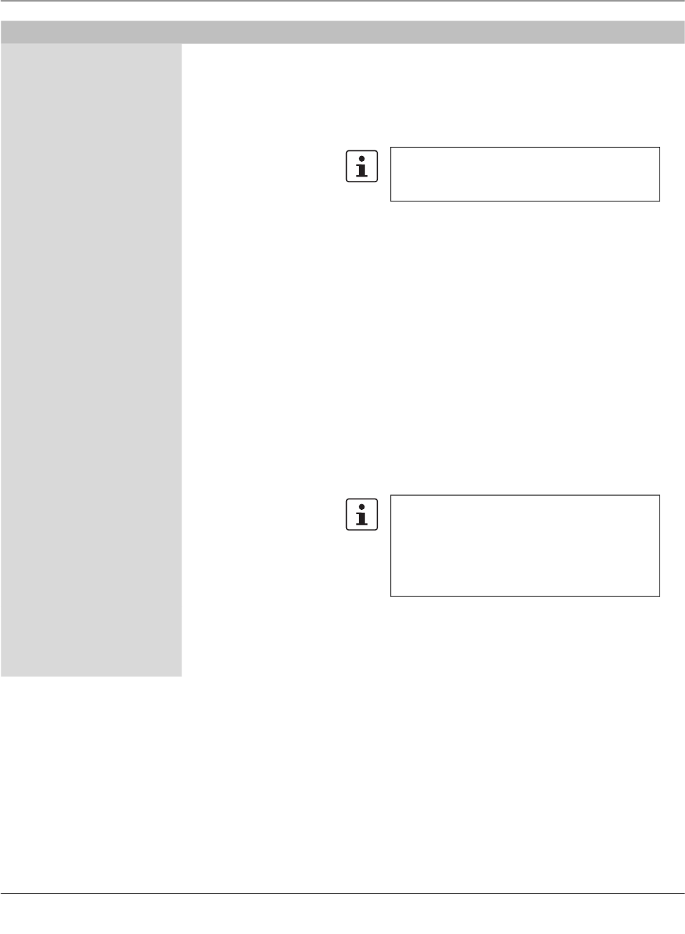
Complex table variables
(e.g. VPN connections)
Contrary to “normal” table variables, adding a row to or deleting a row from a complex
table variable additionally adds or deletes a node from the navigation tree. An example for
a complex table variable are the VPN connections: a VPN connection is represented by a
table row in the overview table and by an additional node in the navigation tree, in which
the settings for the connection can be made. Please note that the table cells of complex
tables are not editable, i.e. all settings have to be made in the leafs of the navigation tree
node.
Complex table variables allow the following choices (for more information on tables
please see “Modifying mGuard table variables” on page 38.
Inherited The behavior is basically the same as described for the “nor-
mal” table variables above. Inherited rows from a template
which also appear as navigation tree nodes are all set to read-
only if Inherited is selected for the complex table variable.
The usage of templates and inherited values is further ex-
plained in “Template properties dialog” on page 69 and
“Working with templates” on page 74.
Custom If you select Custom the table and its associated menu ele-
ments become enabled. Contrary to “normal” table variables
the inherited table rows are not copied from the template to the
device when switching to Custom. Inherited rows cannot be
deleted, but can be edited if Custom is selected. Please note
that changing or editing the rows does not change the rows in
the template. You may also add new rows (nodes) to the table.
Please note that it is possible to switch between
Custom and Inherited without losing any data
while the Properties Dialog is open. But if you
switch from Custom to Inherited, apply your
settings, and then leave the dialog, all custom
rows you entered will be lost.
mdm client – Configuration tasks
111024_en_01 PHOENIX CONTACT 35
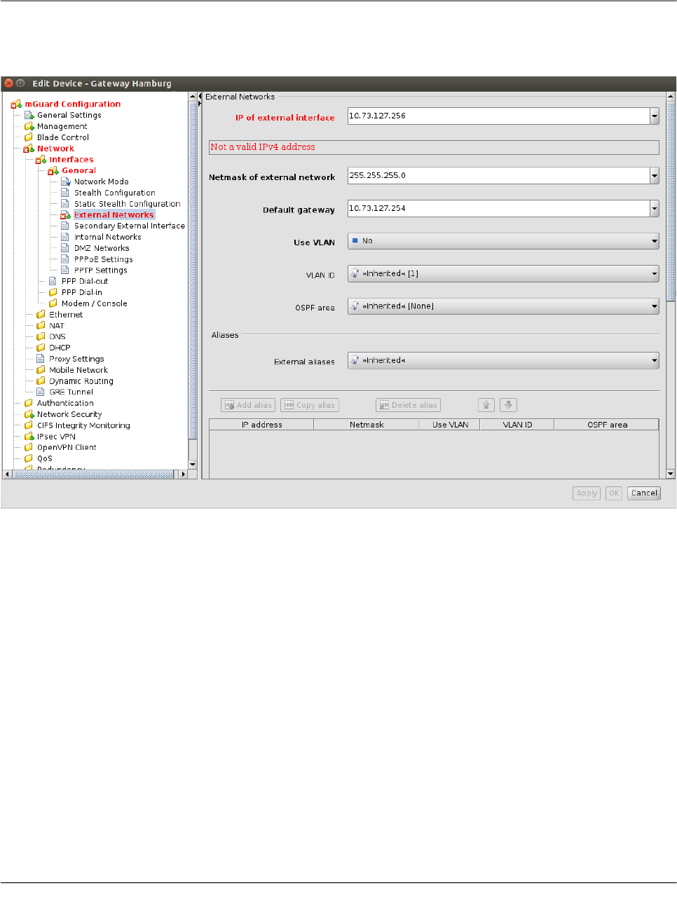
6.1.3 Indication of invalid input
Invalid input will be immediately indicated by a red variable name and by error icons in the
navigation tree, as shown in the following figure for the external IP address:
Figure 6-1 Input verification / invalid input

FL MGUARD DM UNLIMITED 1.15.x
36
PHOENIX CONTACT 111024_en_01
6.1.4 Indication of changed values
The icon in the leafs of the navigation tree (see the following figure) indicates that a
change has been made to a variable in the leaf but has not been applied yet.
Figure 6-2 Indication of non-applied changes
The icon in the leafs of the navigation tree (see the following figure) indicates that set-
tings have been changed in the respective leaf and have been applied.
Figure 6-3 Indication of applied changes
mdm client – Configuration tasks
111024_en_01 PHOENIX CONTACT 37
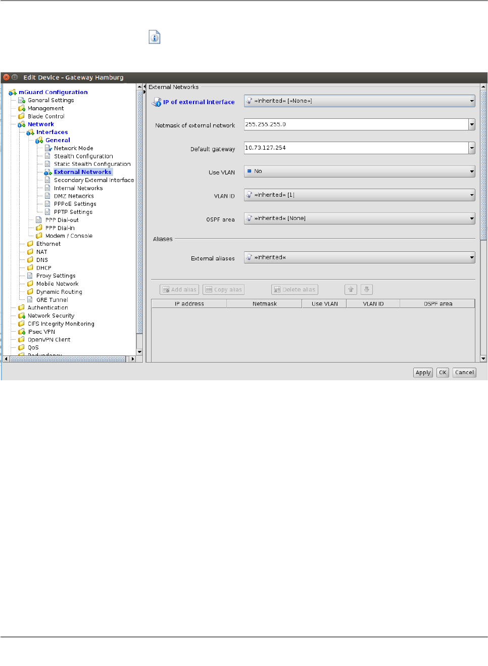
6.1.5 Indication of “None“ value or exhausted pool
The icon in the leafs of the navigation tree (see the following figure) indicates either
– a “None“ value which has not been overridden (set) yet in the template hierarchy or
– a reference to an exhausted pool.
Figure 6-4 Indication of a “None“ value or an exhausted pool

FL MGUARD DM UNLIMITED 1.15.x
38
PHOENIX CONTACT 111024_en_01
6.1.6 Modifying mGuard table variables
The following figure shows an example of a table variable (incoming firewall rules):
Figure 6-5 Modifying table variables
Add, delete, copy, or move
rows
To add, delete, copy, or move rows, please use the respective buttons.
If none of the rows is selected then a click on the Add button will add the row at the begin-
ning of the table. If one or more rows are selected, a new row will be added after the last
selected row.
The Delete button is enabled only if at least one row is selected. It deletes the selected
rows.
The Copy button is enabled only if at least one row is selected. It copies the selected rows
and inserts them after the last selected row.
The Move buttons are enabled only if at least one row is selected. To move the current se-
lection up one row press the button; to move it down please press the button.
Selecting table rows By clicking on a table row with the left mouse button you select it. Multiple rows can be se-
lected as a contiguous block of rows either by first selecting the upper or lower row of the
block and then selecting the opposite row with a left click while holding the <Shift> key.
The Add, Delete, Copy, and Move buttons are enabled only if either Custom or Custom
+ locally appendable is selected. Please refer to the Section mGuard configuration
above.

mdm client – Configuration tasks
111024_en_01 PHOENIX CONTACT 39
Rows can be added to the selection or removed from the selection by clicking with the left
mouse button on the row while pressing the <Ctrl> key.
Changing a table cell To edit a table cell please double click on the cell with the left mouse button. (A single click
selects the table row).
Invalid values in tables An invalid value in a table will not be indicated in the navigation tree, but the cell will be
marked red. If you enter an invalid value in a table cell, and leave the cell e.g. by clicking on
another navigation tree node, the last applied (valid) value will replace the invalid input.
In Firewall tables: If the chosen protocol is neither TCP nor UDP, the configured port will be
ignored. In this case the cell will be marked in yellow.
Row colors The rows of a table may have different colors, depending on the type of row. Inherited rows
from an ancestor template are colored red, green or grey:
– a green row indicates that the row is editable,
– a red row indicates that the row cannot be edited or deleted,
– a grey row indicates that it is an inherited default row (which can be changed)
Figure 6-6 Table row colors
To change a green or grey row it is necessary to switch the value of the table from Inher-
ited to Custom.

FL MGUARD DM UNLIMITED 1.15.x
40
PHOENIX CONTACT 111024_en_01
Context menu Tables can also be edited using the context menu. Please click on the table with the right
mouse button. The following menu will appear:
Figure 6-7 Context menu
6.1.7 Modifying complex table variables
For the definition of a complex table variable please refer to the section mGuard configura-
tion above. Basically the previous section also applies to complex table variables. However
there are some differences that the user should be aware of.
The following figure shows an example of a complex table variable (VPN connections):
Figure 6-8 Modifying complex table variables
A complex table does not allow to move rows (the respective buttons are missing). Further-
more the cells of complex tables cannot be edited. Adding a row to a complex table also re-
sults in adding a node to the navigation tree (see Figure 6-8).
The Add, Copy, and Delete buttons are enabled only if Custom or Custom+Locally ap-
pendable is selected. Please refer to the Section mGuard configuration above.

mdm client – Configuration tasks
111024_en_01 PHOENIX CONTACT 41
6.1.8 Applying changes to the configuration
Changes made to the configuration are permanently stored with the Apply button (at the
bottom of the dialog). If you make any changes without applying them, you can discard your
changes by closing the dialog with the Cancel button. You can also apply your changes by
closing the dialog with the OK button.
Please note that the configuration is not automatically transferred to the mGuard after ap-
plying a change. To transfer the configuration to an mGuard, you have to upload the con-
figuration file to the mGuard (see Chapter 7.1).
FL MGUARD DM UNLIMITED 1.15.x
42
PHOENIX CONTACT 111024_en_01
6.2 Default values
If a default value is changed in the mGuard firmware, the management of this value in mdm
will be affected:
1. if a firmware version of a managed device is upgraded to a firmware version with a
changed default value,
2. if an inheriting child with a different mGuard firmware version than its parent inherits a
value with a different default value.
The related behavior of mdm is described below.
6.2.1 Behavior of changed default values
In mGuard firmware version 8.5 and 8.6 the following default values have been changed
(see Table 6-1 on page 42:).
If a device/template is upgraded to an mGuard firmware version (8.5 or 8.6), and a new de-
fault value differs from the old default value (see table above), the following applies:
If the default value is in default configuration and inherited (along the complete inheritance
chain), then the old default value will be kept after the upgrade. In this case the value type
(of the table) will be changed from “Inherited“ to “Custom“.
Table 6-1 Changed mGuard default values
Changed
in version
Path to value in the mGuard web interface Value old Value new
8.5.0 IPsec VPN >> Connections >> EDIT >> IKE Options >> ISAKMP SA (Key Exchange) 3DES (Encryption) AES-256
8.5.0 IPsec VPN >> Connections >> EDIT >> IKE Options >> IPsec SA (Data Exchange) 3DES (Encryption) AES-256
8.6.0 CIFS Integrity Monitoring >> CIFS Integrity Checking >> Settings >> Checking of Shares SHA-1 (Hash) SHA-256
8.6.0 OpenVPN Client -> Connections >> EDIT >> Tunnel Settings >> Data Encryption Blowfish (Encryption) AES-256
8.6.0 Redundancy >> Firewall Redundancy >> Redundancy >> Encrypted State Synchronization 3DES (Encryption) AES-256
8.6.0 SHA-1 (Hash) SHA-256
8.5.0 Network Security >> Packet Filter >> Incoming/Outgoing See mGuard firmware manual 8.5.x for fur-
ther information, avaliableonline or at phoe-
nixcontact.net/products.

mdm client – Configuration tasks
111024_en_01 PHOENIX CONTACT 43
6.2.2 Inheritance of changed default values
The inheritance of changed default values depends on the installed mdm version and the
mGuard firmware version of the affected device/template.
General behavior in mdm < 1.8.0:
If default values (value type = “Inherited“ and not “Local“ or “Custom“) of the child differ from
the default values of the parent (value type = “Inherited“ along the complete inheritance
chain), the inheritance will behave as follows:
1. The child keeps the default values corresponding to the child‘s firmware version. The
value type will remain „
Inherited
“.
General behavior in mdm 1.8.0 or later:
If default values (value type = “Inherited“ and not “Local“ or “Custom“) of the child differ from
the default values of the parent (value type = “Inherited“ along the complete inheritance
chain), the inheritance will behave as follows:
1. Default values that have been changed in mGuard firmware versions < 8.5:
– The child keeps the default values corresponding to the child‘s firmware version.
The value type will remain „
Inherited
“.
2. Default values that have been changed in mGuard firmware versions 8.5 or later:
– The child inherits the default values of the parent. The value type will remain „
In-
herited
“.

FL MGUARD DM UNLIMITED 1.15.x
44
PHOENIX CONTACT 111024_en_01
6.3 Configure Devices
6.3.1 Device overview table
Please select the Device tab to access the device overview table.:
Figure 6-9 mdm main window with device table
Device table columns The device overview table contains the following columns (see below).
The column width can be changed by placing the cursor on the header of the table at the
border of two columns and dragging the border to the desired location. The order of the
columns can be changed by dragging the column header to a different location.
Device table columns
Status
C
The column labeled with
C
shows the configuration status of the device, which indicates
whether the configuration on the mGuard differs from the configuration of the device in
mdm.
The configuration status can take the following values.
Unknown mdm is not able to determine whether the configuration of your
mGuard is up-to-date.
OK The configuration in mdm is identical to the current configura-
tion of your mGuard.
Changed The configuration in mdm is different to the current configura-
tion of your mGuard, i.e. the changes made with mdm have
not yet been uploaded to the device.
mdm client – Configuration tasks
111024_en_01 PHOENIX CONTACT 45
Locked The configuration is locked by another user. This can happen
if another user opens the Device properties dialog or the Tem-
plate properties dialog of an assigned template.
Status
U
The column labled with
U
shows the upload status of the device, which indicates the sta-
tus of a pending upload or the result of the last upload. Please refer to “Upload configura-
tions to mGuard devices” on page 99 on how to upload configurations to the devices.
The upload status can take the following values.
Unknown mdm could not determine the status yet, since no upload has
taken place.
Up to date The configuration on the device has not changed because it
already was up to date.
Updated The configuration on the device has been updated.
Configuration
exported
The configuration files have been successfully exported to the
file system.
Pull feedback received The mdm server has received a configuration pull feedback
from the HTTPS server, but it could not be determined
whether the configuration on the device is now up to date. This
status indicates that the device has pulled a configuration file,
but has not yet applied it, or that the configuration is outdated,
because it has been changed in mdm after the export to the
HTTPS server.
Device credentials
update
Indicates that an SSH host key reset was performed.
Configuration
invalid
mdm indicates that the current configuration is invalid, e.g. a
None value (see “Template configuration” on page 73) in the
template has not been overriden in the device.
Device table columns
Please note that configuration changes per-
formed by other means than mdm cannot be
detected, i.e. the configuration status is dis-
played correctly only if solely the netadmin user
changes the mGuard configuration locally on
the device.
If a template is changed the configuration status
of all mGuards using this template is set to out-
of-date, no matter whether the template change
affected the device configuration or not.
Please refer to Chapter 5.2 if you would like to
manually reset the configuration status to up-to-
date.

FL MGUARD DM UNLIMITED 1.15.x
46
PHOENIX CONTACT 111024_en_01
Changed The configuration in mdm is different to the current configura-
tion of your mGuard, i.e. the changes made with mdm have
not yet been uploaded to the device.

mdm client – Configuration tasks
111024_en_01 PHOENIX CONTACT 47
Upload or export error A permanent error has occured and mdm could not recover
from the error or the maximum number of retries for the
SSH/HTTPS configuration push has been reached without ac-
cessing the mGuard. The cause of the error is displayed in the
log window.
– Host authentication failed
This error indicates that the SSH host authentication
failed. This can be an indicator of an attack, but most likely
it is due to the fact that a failing device was replaced. Be-
fore you continue please make sure that the devices in
question was indeed replaced. To continue remove the
device’s active SSH hostkey with the option Set Current
Device Credentials in the context menu of the device
overview table (select the Reset SSH Host Key check-
box). The new SSH hostkey will be set with the next SSH
connection.
– User authentication failed
This error indicates that the user credentials (e. g. user
name admin and the password stored in the devices ac-
tive password) were not accepted. It can also indicate that
the SSH authentication method password was not ac-
cepted by the mGuard.
– I/O failed / Upload failed
This error indicates that an input/ouput (I/O) failure has
occurred. In the case of SSH uploads this is probably a
transient error and a retry should be scheduled. In the
case of filesystem output (pull config) the failure is proba-
bly not transient and the cause should be examined by the
user.
– Concurrent configuration upload
This indicates that another upload is currently active for
the same device. An example is an SSH/HTTPS upload
that detects a running pull config script. The usual way to
handle this is to reschedule this update.
– Configuration rejected
This indicates that the device has rejected the configura-
tion as invalid.
Upload timeout This indicates that the SSH connection to the device has
timed out, i.e. the device has no reacted to the commands ini-
tiated by the mdm within a given (configurable) time frame. If
the configuration contains a large number of VPN connec-
tions, it might be necessary to increase the timeout; see
Chapter 10.1, node service » storage » update » ssh » dead-
PeerDetectionTimeout (“Key deadPeerDetectionTimeout” on
page 153).
License could not be
installed
This indicates that an mGuard license file could not be in-
stalled on the device.
Pull configuration
rolled back
This indicates that a configuration pulled by the device was
rolled back.
Device table columns

FL MGUARD DM UNLIMITED 1.15.x
48
PHOENIX CONTACT 111024_en_01
Pull configuration
blocked due to previ-
ous rollback
This indicates that configuration is blocked due to a previous
rollback.
Saving configuration
for rollback failed
This indicates that saving the rollback configuration failed, the
configuration was not applied.
Pulled configuration
invalid
This indicates the device detected an invalid pull configuration
and therefore the configuration was not applied.
Firmware upgrade
failed
The scheduled firmware upgrade failed.
Queued for upload or
export
The device is currently in the upload queue. Depending on the
settings for the configuration push retries and the waiting time
between retries the device might stay in the queue for a while.
Upload or export run-
ning
The device has been accessed and the configuration file is
currently being uploaded.
Requeued for upload
or export
If the device is not accessible, then it will be requeued and
after waiting time between retries the upload will start again. If
after configuration push retries the device has not been ac-
cessed an error is shown. This icon is also shown during an
ongoing firmware upgrade, since mdm will periodically poll the
device for the result of the firmware upgrade.
Management ID The column shows the Management ID of the device.
Templates The column shows a comma-separated list of the device’s ancestor templates. The first
item in the list is the immediate parent template.
Status
V
The column labled with
V
shows the VPN group status.
Not a member of a
VPN group
Hovering over one of the latter two icons with the mouse cur-
sor will display a tooltip, listing the VPN group(s) in which the
device is a member.
Member of exactly one
VPN group
Member of more than
one VPN group
Version The column shows the firmware version currently selected in mdm for this device.
Status
F
The column labled with
F
shows the Firmware status.
Unknown The status is unknown.
OK The firmware upgrade was successful and the firmware ver-
sion configured in mdm corresponds to the firmware version
on the device.
Upgrade scheduled The upgrade is scheduled.
Upgrade running The upgrade is running.
Version mismatch The Firmware version configured in mdm and firmware ver-
sion on device do not match.
Error An error occured during firmware upgrade.
Device table columns
mdm client – Configuration tasks
111024_en_01 PHOENIX CONTACT 49
Version on device The column shows the firmware version currently installed on the device. Please refer to
“Device properties dialog” on page 60 for more information.
If the device is in redundancy mode (see “Redundancy mode” on page 118 for more de-
tails), the firmware versions of both devices, separated by a comma, are shown.
Accessible via The column shows the IP address or hostname which is used by mdm to access the de-
vice. This address can be configured in the General settings of the Device properties di-
alog (see “Device properties dialog” on page 60). Without an Accessible via address it is
not possible to push configurations to the device, import ATV profile configurations or
open the Web GUI of the device. Please note that this address might not correspond to
the internal or external address of the mGuard if NAT is involved.
If an SSH port has been set manually in the General settings or is obtained from the
configured Port for incoming SHH connections it will be displayed as well.
If the device is in redundancy mode (see “Redundancy mode” on page 118 for more de-
tails), the Accessible via addresses of both devices, separated by a comma, are shown.
Upload scheduled at The column shows the date/time the next configuration upload is scheduled for this de-
vice.
Serial number The column shows the serial number of this device (see “Device properties dialog” on
page 60).
If the device is in redundancy mode (see “Redundancy mode” on page 118 for more de-
tails), the serial numbers of both devices, separated by a comma, are shown.
Pull config filename If the configuration is exported to the file system, a unique ID is used as name of the con-
figuration file. The filename of the configuration file is shown in this column.
Location The column shows the value of the SNMP Location variable (SYS_LOCATION). If the lo-
cation is empty, a “-” character is displayed.
If the device is in redundancy mode (see “Redundancy mode” on page 118 for more de-
tails) and different locations are set for each physical device, the locations of both de-
vices, separated by a comma, are shown.
Hardware The column shows the hardware flavor of the device. See “Hardware flavors” on page 26
for more details.
Status
K
The column labeled with
K
shows the size of the ssh and https cryptographic keys on the
mGuard. The size will be updated every time the mdm has access to the mGuard (only
with devices with installed firmware version 7.5 or later). mGuard devices with installed
firmware version < 7.5 will not update this information.
Unknown The size is unknown.
1024 bits The size is 1024 bits.
2048 bits The size is 2048 bits.
Key renewal sched-
uled
It is recommended to renew 1024 bit keys (see “Set Current
Device Credentials” on page 58” for more details).
Device table columns

FL MGUARD DM UNLIMITED 1.15.x
50
PHOENIX CONTACT 111024_en_01
Filtering and sorting the
table
The header of the table can be used to sort the table entries. A click on a header of a column
will activate the (primary) sort based on this column. This is indicated by the arrow in the col-
umn header. A second click on the same header will reverse the sort order. Clicking on an-
other column header activates the sort based on this new column, the previously activated
column will be used as secondary sorting criterion.
The first row of the table accepts the input of regular expressions (please refer to “Glossary”
on page 163, Regular expressions), which can be used to efficiently filter the table entries.
Filtering based on regular expressions is not used for columns that do not contain text (col-
umns C, U, V, or F).
The filter history will be saved for the current user and can be accessed using the drop down
functionality of the filter fields.
Creating devices There are several ways to create new devices:
1. Open the context menu by clicking on the device table with the right mouse button. To
open the Device properties dialog for a new mGuard please select Add in the context
menu.
2. Select the Device tab and click on the icon in the menu bar to open the Device
properties dialog for a new mGuard.
3. Select New » Device in the main menu to open the Device properties dialog for a new
mGuard.
4. Select New » Device Import in the main menu to import new devices.
Editing devices There are several ways to edit a device:
1. Double-click with the left mouse button on the device in the table to open the Device
properties dialog.
2. Select the device with the left mouse button and open the context menu by pressing the
right mouse button. Then select Edit to open the Device properties dialog.
Last sync The column shows the date on which each device was last synchronized successfully
with mdm. Synchronization means either updated by
– an SSH upload to the device (upload via SSH),
– a pull export to the device via an HTTPS configuration pull server + feedback (prepare
pull configuration) or
– an online import from the device to mdm (Import ATV Profile).
The column can be searched and sorted chronologically.
Device table columns
If the device has been updated via pull export (pull configuration), Last sync
will only display this synchronization, if all of the following apply:
1. the device configuration in mdm has not changed since the pull export
was scheduled,
2. no additional SSH upload took place after the pull export,
3. the pull export actually changed the configuration on the mGuard device
(subsequent pull feedback messages, where no configuration change
takes place, are not registered as synchronization events).

mdm client – Configuration tasks
111024_en_01 PHOENIX CONTACT 51
3. Select the device to be modified in the device table. Select Edit » Edit Item in the main
menu to open the Device properties dialog.
Deleting devices There are several methods to delete devices:
1. Select the device(s) in the device table and open the context menu by clicking with the
right mouse button. To delete the devices please select Delete in the context menu.
2. Select the devices to be deleted in the table and click on the icon in the menu bar.
The Edit entry in the context menu and the Edit button in the toolbar are only
enabled if exactly one device is selected in the device table.

FL MGUARD DM UNLIMITED 1.15.x
52
PHOENIX CONTACT 111024_en_01
6.3.2 Device context menu
The device context menu contains the following entries (see below).

mdm client – Configuration tasks
111024_en_01 PHOENIX CONTACT 53
Device context menu
Add Create a new device and open the Device properties dialog of
the new device.
Edit Edit the selected device (only active if exactly one device is
selected in the overview table).
Duplicate To create a duplicate of a device please open the context
menu by clicking with the right mouse button on the device in
the device table. Select Duplicate in the context menu. mdm
will create a copy of the device and append the string
_copy<n> (<n> is a number) to the Management ID of the
new device. Please note that the Duplicate menu entry is
only enabled if exactly one device is selected in the device
table.
Import ATV Profile Import ATV profiles into the selected device(s):
Figure 6-10 ATV import
The following options are available when importing a profile:
Select Inherited where possible
If this option is selected, variables, for which the imported
value (i.e. the value in the ATV profile) is the same as the in-
herited value, are set to Inherited. Otherwise, all variables con-
tained in the profile are set to Custom, regardless of their
value.
FL MGUARD DM UNLIMITED 1.15.x
54
PHOENIX CONTACT 111024_en_01
Ignore table rows added by the netadmin user
Tables rows that were created by the local netadmin user on
the mGuard are not imported.
Select from File/Device
If File is selected, the ATV profile to import is uploaded as a
file. This option is only available if an ATV import into a single
device is performed.
If Device is selected, mdm downloads the ATV profile from the
mGuard. This requires that mdm can log into the mGuard
with the ssh protocol; the Accessible via address must be
set. The related SSH port can be configured optionally (see
“Accessi-
ble via” on page 62).
Import into <A>/<B>
If the device is in redundancy mode (see “Redundancy mode”
on page 118 for more details), the profile can be imported into
the configuration variables for the first or the second physical
device.
A few configuration variables cannot be imported and must be
set manually if necessary: the passwords of the root and
admin users, the passwords of the user firewall users, and cer-
tificate revocation lists (CRLs). ATV profiles downloaded from
an mGuard either do not contain these variables at all or con-
tain them in encrypted (hashed) form. Please note that mdm
does import the password of the netadmin user if it is found in
the ATV profile, but a profile downloaded from an mGuard
does not contain it.
Web Configure Open the Web GUI of the device, if the device is accessible
(see also Accessible via address in “Device properties dia-
log” on page 60).
Export Generate a CSV file containing the basic properties (but not
the configurations) of the selected devices. The file is suitable
to imported into mdm again (see “mdm main menu” on
page 19, Device Import.
Delete Delete the selected devices.
Device context menu
Any change made with the Web GUI will be
overwritten by the next mdm configuration up-
load (except for changes made as netadmin to
local variables).

mdm client – Configuration tasks
111024_en_01 PHOENIX CONTACT 55
Set Firmware Version Upgrade the firmware version to a new version.
Since different firmware versions of the mGuard software
have different sets of variables, the firmware version corre-
sponding to the installed firmware on the mGuard has to be
selected here.
Please refer to “Manage firmware upgrades with mdm” on
page 115 for more details.
Set Hardware Flavor Set the hardware flavor. Please refer to “Hardware flavors” on
page 26 for more details.
Assign Template Open the Assign template dialog and assign a template to the
selected devices.
Add to VPN Group Opens a dialog to add the selected devices to a VPN group.
Remove from VPN
Group
Opens a dialog to remove the selected devices from a VPN
group.
Upload Open the Upload dialog. Please refer to “Upload configura-
tions to mGuard devices” on page 99 for more details.
Cancel Upload Cancel the scheduled upload for the selected devices.
Device context menu
CAUTION: Irreversible changes
Upgrading the firmware version of the device
might change default variable values at the tar-
get version.
It is not possible to downgrade to an older re-
lease. So please be very careful when changing
the firmware version. See “Firmware release
settings and inheritance” on page 78 for more
details.
Once the upgrade has been performed, check
all variable changes at the "Device Configura-
tion History" (see “The configuration history dia-
log” on page 119).
NOTE: New default values in mGuard firm-
ware 8.5 and 8.6
If a default value in the mGuard firmware is
changed, the management of this value in mdm
will be affected:
1. if a firmware version of a managed device
is upgraded to a firmware version with a
changed default value,
2. if a child with a different mGuard firmware
version than its parent inherits a value with
a different default value.
The related behavior of mdm is described in the
Chapter 6.2.1 (“Behavior of changed default
values” on page 42).
FL MGUARD DM UNLIMITED 1.15.x
56
PHOENIX CONTACT 111024_en_01
Set Upload State The upload status will never be set to successfully uploaded
automatically if no push upload is performed and no pull feed-
back from the configuration server is received (e.g. in a usage
scenario where the exported configuration profiles are in-
stalled manually on the devices). You can use this option to
set the upload state to successfully uploaded manually.
Please select the device in the device table, open the context
menu with a right click and then select Set upload state.
Export ECS Files Download (encrypted) ECS files for the selected devices.
Per default the ECS files will be encrypted. The user root and
other authorized users can disable encryption and download
unencrypted ECS files. (For granting rights to authorized
users see “Manage users, roles, and permissions” on
page 107).
ECS files can be used to configure mGuard devices that sup-
port this mechanism through SD cards; please refer to the
mGuard firmware manual
for more details. A dialog is opened
where the directory where to store the ECS files can be se-
lected.
Show Device Configu-
ration History
Open the configuration history dialog. Please refer to “The
configuration history dialog” on page 119 for more detailed in-
formation.
Generate Report of
Changes to Device
Configuration
Open a dialog to generate a report of changes to device con-
figurations. Please refer to “Report of changes” on page 126
for more detailed information.
Device context menu
If a device is in a state in which an upload would
fail (e.g. if a None value has not been overrid-
den, cf. Chapter 6.4.4), it is not possible to set
the upload state to successfully uploaded.
The prerequisites for creating encrypted ECS
files are same as for encrypted profiles. See
““Profile encryption” on page 101”.

mdm client – Configuration tasks
111024_en_01 PHOENIX CONTACT 57
Changes since last
Sync
A configuration dialog opens, showing performed changes
since last synchronization.
Synchronization means either
– an SSH upload to the device (upload via SSH),
– a pull export to the device via an HTTPS configuration pull
server + feedback (prepare pull configuration),
– an online import from the device to mdm (Import ATV Pro-
file).
If the device has been successfully synchronized once, the
configuration changes since the last upload/online import are
shown.
The behavior is similar to selecting two history entries in the
"Device Configuration History" Dialog and clicking on "Com-
pare..." (see “Comparison of historic configurations” on
page 123).
If the device has never been synchronized, the configuration
changes since the device was created are shown.
If the current configuration is the last synchronized configura-
tion, the current configuration is shown.
Upload/Import History Displays an overview of the last synchronization actions.
Synchronization means either
– an SSH upload to the device (upload via SSH),
– a pull export to the device via an HTTPS configuration pull
server + feedback (prepare pull configuration), or
– an online import from the device to mdm (Import ATV Pro-
file).
Device context menu
If the device has been updated via pull export
(pull configuration), a synchronization will only
be registered and displayed, if all of the follow-
ing apply:
1. the device configuration in mdm has not
changed since the pull export was sched-
uled,
2. no additional SSH upload took place after
the pull export and
3. the pull export actually changed the config-
uration on the mGuard device
(subsequent pull feedback messages,
where no configuration change takes
place, are not registered as synchroniza-
tion events).
FL MGUARD DM UNLIMITED 1.15.x
58
PHOENIX CONTACT 111024_en_01
Set Current Device
Credentials
Open a dialog in which the device credentials can be set. The
following attributes can be set:
Active root and admin passwords
The active passwords are the passwords that are currently in
effect on the device. They may differ from the configured pass-
words when the current configuration has not yet been up-
loaded to or been pulled from the mGuard. mdm keeps track
of the active passwords since the root password is needed to
set a new root password, and the admin password is needed
to log into the mGuard.
Reset SSH Host Key
mdm stores the SSH key of an mGuard after the initial contact.
In case an mGuard has been replaced, the SSH keys do not
match and mdm will refuse any connection to the replaced de-
vice. This function can be used to reset the SSH key.
Renew Secure Key Length
If this is selected, the mGuard will generate ssh and https keys
on the next configuration upload or pull.
Device Replacement Resets all settings specific to a device to default values. This
can be used if a defective device has been replaced.
– The following settings are reset:
– Firmware Version on Device
– Serial Number
– Flash ID
– SSH Hostkey
– Profile Encryption Key
– Licenses associated with the device
Set Redundancy Mode Open a dialog in which redundancy mode can be enabled or
disabled for the selected devices.
Generate Redun-
dancy Passphrases
Set the redundancy passphrase variables in the device con-
figuration to random values.
Generate License Please refer to “Manage license vouchers and device li-
censes” on page 104 for details regarding the license man-
agement.
Refresh License Please refer to “Manage license vouchers and device li-
censes” on page 104 for details regarding the license man-
agement.
Get Profile Key Obtain a profile key from the license server. Please refer to
section ““Profile encryption” on page 101” or details.
Device context menu
It is recommended to generate new keys if 1024
bit keys are still in use.

mdm client – Configuration tasks
111024_en_01 PHOENIX CONTACT 59
Enable/Disable profile
encryption
Enable or disable encryption of configuration profiles for the
selected devices. Please refer to section ““Profile encryption”
on page 101” for details.
Firmware Upgrade »
Schedule upgrade to
latest patches
Schedule a firmware upgrade to the latest available patches.
Please refer to “Manage firmware upgrades with mdm” on
page 115 for more details.
Firmware Upgrade »
Schedule upgrade to
latest minor release
Schedule a firmware upgrade to the latest available minor re-
lease. Please refer to “Manage firmware upgrades with mdm”
on page 115 for more details.
Firmware Upgrade »
Schedule upgrade to
next major version
Schedule a firmware upgrade to the next major version.
Please refer to “Manage firmware upgrades with mdm” on
page 115 for more details.
Firmware Upgrade »
Unschedule upgrade
Unschedule a firmware upgrade.
Certificate Handling »
Request additional
certificate
Request a machine certificate for the device and append it to
the list of existing machine certificates. Please refer to “Ma-
chine certificates” on page 111 for more details.
Certificate Handling »
Request replacement
certificate
Request a machine certificate for the device and replace any
existing machine certificates with the new one. Please refer to
“Machine certificates” on page 111 for more details.
Certificate Handling »
Issue and Export Cer-
tificate Requests
Generate certificate requests for manual certificate enroll-
ment. Please refer to “Machine certificates” on page 111 for
more detailed information.
Select All Select all devices not excluded by the table filter.
Device context menu
All existing machine certificates in the device
are deleted, even if they have been imported
manually. As a result, the device has a single
machine certificate (the newly requested one).
This function is therefore most useful for devic-
es which contain a single machine certificate.

FL MGUARD DM UNLIMITED 1.15.x
60
PHOENIX CONTACT 111024_en_01
6.3.3 Device properties dialog
The Device properties dialog allows to configure the mGuard variables and their associated
settings for a device.
For information on how to create, delete or edit devices please refer to “mdm main window”
on page 18.
Figure 6-11 Device properties dialog

mdm client – Configuration tasks
111024_en_01 PHOENIX CONTACT 61
Similar to the Template properties dialog (see Chapter 6.4.3) the Device properties dialog
contains a navigation tree on the left side that resembles the menu structure of the mGuard
Web GUI. The navigation tree allows you to conveniently navigate to each mGuard variable.
The Device properties dialog contains the entry General settings for the configuration of
additional parameters related to mdm. The following parameters can be set in the General
settings.
Device properties dialog
General Settings Management ID This ID is used to identify the device within mdm. The Manage-
ment ID must be unique.
Firmware version Upgrade the firmware version to a new version.
Since different firmware versions of the mGuard software
have different sets of variables, the firmware version corre-
sponding to the installed firmware on the mGuard has to be
selected here.
CAUTION: Irreversible changes
Upgrading the firmware version of the device
might change default variable values at the tar-
get version.
It is not possible to downgrade to an older re-
lease. So please be very careful when changing
the firmware version. See “Firmware release
settings and inheritance” on page 78 for more
details.
Once the upgrade has been performed, check
all variable changes at the "Device Configura-
tion History" (see “The configuration history dia-
log” on page 119).
NOTE: New default values in mGuard firm-
ware 8.5 and 8.6
If a default value in the mGuard firmware is
changed, the management of this value in mdm
will be affected:
1. if a firmware version of a managed device
is upgraded to a firmware version with a
changed default value,
2. if a child with a different mGuard firmware
version than its parent inherits a value with
a different default value.
The related behavior of mdm is described in the
Chapter 6.2.1 (“Behavior of changed default
values” on page 42).
For more information on how to manage firm-
ware upgrades of your devices with mdm
please refer to Chapter 7.6.

FL MGUARD DM UNLIMITED 1.15.x
62
PHOENIX CONTACT 111024_en_01
Firmware version on
device
This field represents the firmware version currently installed
on the device. It can be manually set, but is overridden with the
value found on the device every time a push upload is per-
formed or a pull feedback is received.
Template The parent template of the device.
Redundancy support The redundancy support of the device can be enabled or dis-
abled.
Accessible via This is the IP address or hostname used by the mdm server to
access the mGuard for an SSH push export of the configura-
tion, an ATV profile import of the configuration or to open the
web interface.
Please refer to “Upload configurations to mGuard devices” on
page 99 for more information on the upload procedure.
The following values are available for Accessible via (the
SSH port and the Web configuration port can be specified
in the fields below.
Not online manageable
The device is not managed via SSH push.
Internal interface in auto stealth mode [1.1.1.1]
mdm accesses the mGuard using the address 1.1.1.1 (ad-
dress of internal interface in automatic stealth mode).
Stealth management address
mdm accesses the external or internal interface of the mGuard
in stealth mode.
First external IP address
mdm accesses the external interface of the mGuard in router
mode.
First internal IP address
mdm accesses the internal interface of the mGuard in router
mode.
Custom value
A custom value (IP address or hostname) might be required to
access the mGuard in NAT scenarios.
Device properties dialog

mdm client – Configuration tasks
111024_en_01 PHOENIX CONTACT 63
SSH port This is the SSH port number used by the mdm server to ac-
cess the mGuard for an SSH push export or an ATV profile im-
port of the configuration.
In some cases it might be necessary to change the standard
SSH port to connect to the device (e.g. the device is not con-
nected to the Internet but gets a port forwarded from the fire-
wall).
If Port for incoming SSH connections is selected, the port
configured in Management >> System Settings >> Shell Ac-
cess >> Shell Access Options >> Port for incoming SSH con-
nections will be used and displayed in the overview table.
Please refer to “Upload configurations to mGuard devices” on
page 99 for more information on the upload procedure.
Web configuration
port
This is the HTTPS port number used to access the graphical
web interface of the mGuard.
In some cases it might be necessary to change the standard
HTTPS port to connect to the web interface of the device (e.g.
the device gets a port forwarded from the firewall).
If Remote HTTPS TCP port is selected, the port configured
in Management >> Web Settings >> Access >> HTTPS Web
Access >> Remote HTTPS TCP port will be used.
Pull filename (read
only)
If the configuration is exported to the file system, a unique ID,
which is automatically assigned and cannot be changed, is
used as name for the configuration file. The filename is shown
in this field. Optionally, additional export files following a differ-
ent naming scheme can be generated; please refer to “mdm
server (preferences.xml file)” on page 149 for more informa-
tion.
Serial number The serial number of the device.
The serial number is required for the license handling, espe-
cially the license request and refresh (see “Request/gener-
ate licenses” on page 104).
It can be manually set, but is overridden with the value found
on the device every time a push upload is performed or a pull
feedback is received. If no push upload is ever performed and
no pull feedback is ever received (e.g. in a usage scenario
where the exported configuration profiles are installed manu-
ally on the devices), the serial number has to be entered here
if you would like to create pull configuration filenames contain-
ing the serial number.
Flash ID The flash ID of the device.
The flash ID is required for the license handling, especially for
the license refresh (see “Refresh licenses” on page 106).
It can be manually set, but is overridden with the value found
on the device every time a push upload is performed or a pull
feedback is received.
Device properties dialog

FL MGUARD DM UNLIMITED 1.15.x
64
PHOENIX CONTACT 111024_en_01
Comment An optional comment.
Hardware flavor The hardware flavor of the device (see “Hardware flavors” on
page 26). Setting it to rs2000 has the effect that variables not
supported by this platform are omitted.
Profile encryption Enable or disable encryption of configuration profiles for the
selected devices. Please refer to section ““Profile encryption”
on page 101” for details.
Additional ATV
include
This is a text field for additional settings that should be in-
cluded in the configuration file of the mGuard. The input has to
adhere to the mGuard configuration file conventions. You can
also import the contents of a text file in the field by selecting a
file with the File Chooser icon.
Device properties dialog
Please note that the included configuration will
be appended to the generated mdm settings,
and therefore settings for the same variable in
the include field will override settings generated
by mdm.

mdm client – Configuration tasks
111024_en_01 PHOENIX CONTACT 65
6.4 Configure templates
6.4.1 Template overview table
Please select the Template tab to access the template overview table.
Figure 6-12 The mdm main window with template table
Template table columns The template overview table contains the following columns.
The column width can be changed by placing the cursor on the header of the table at the
border of two columns and dragging the border to the desired location. The order of the
columns can be changed by dragging the column header to a different location.
Template table columns
Status (
S
) The status icon shows whether the template is currently
locked.
Name The name assigned to the template. The name can be set in
the General Settings of the Template properties dialog (see
“Template properties dialog” on page 69).
Templates A comma-separated list of the template’s ancestor templates.
The first item in the list is the immediate parent template.
Version The mGuard firmware version that is used for the template.
Comment Optional comment. The comment can be set in the General
Settings of the Template properties dialog (see “Template
properties dialog” on page 69).
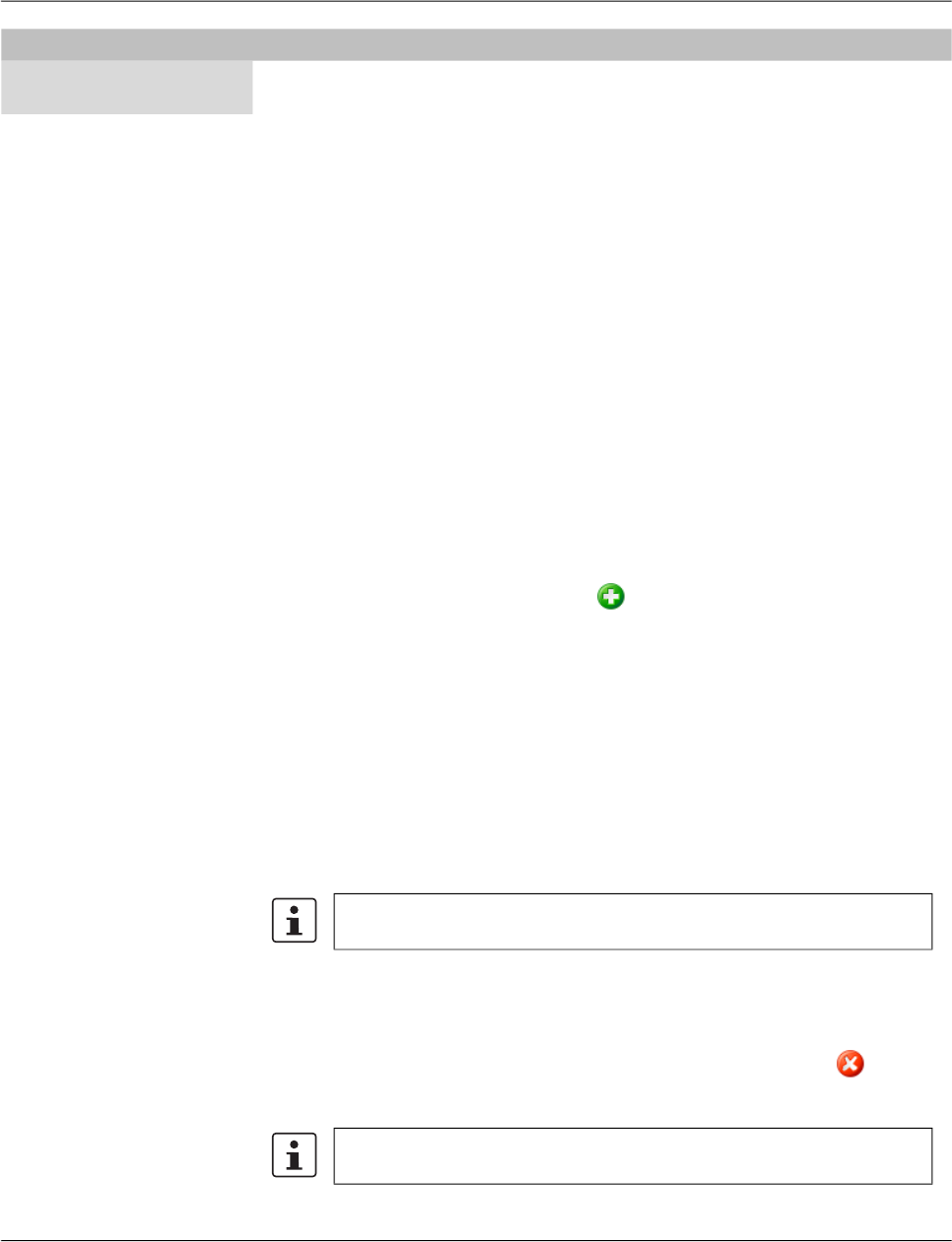
FL MGUARD DM UNLIMITED 1.15.x
66
PHOENIX CONTACT 111024_en_01
Filtering and sorting the
table
The header of the table can be used to sort the table entries. A click on a header of a column
will activate the (primary) sort based on this column. This is indicated by the arrow in the col-
umn header. A second click on the same header will reverse the sort order. Clicking on an-
other column header activates the sort based on this new column, the previously activated
column will be used as secondary sorting criterion.
The first row of the table accepts the input of regular expressions (please refer to
Chapter 11, Regular expressions), which can be used to efficiently filter the table entries.
Filtering based on regular expressions is not used for the column that does not contain text
(i.e. column S).
The filter criterion for the Use count column is not interpreted as a regular expression, but
as a comma-separated list of numbers or number ranges
(e.g. 0,2-3).
The filter history will be saved for the current user and can be accessed using the drop down
functionality of the filter fields.
Creating templates There are several ways to create new templates:
1. Open the context menu by clicking on the template table with the right mouse button.
To open the Template properties dialog for a new template please select Add in the
context menu.
2. Select the Template tab and click on the icon in the menu bar to open the Template
properties dialog for a new template.
3. Select New » Template in the main menu to open the Template properties dialog for a
new template.
Editing templates There are several ways to edit a template:
1. Double-click with the left mouse button on the template in the table to open the Tem-
plate properties dialog.
2. Select the template with the left mouse button and open the context menu by pressing
the right mouse button. Then select Edit to open the Template properties dialog.
3. Select the template to be modified in the template table. Select Edit » Edit Item in the
main menu to open the Template properties dialog.
Deleting templates There are several methods to delete templates:
1. Select the template(s) and open the context menu by clicking with the right mouse but-
ton. To delete the templates please select Delete in the context menu.
2. Select the templates to be deleted in the template table and click on the icon in the
menu bar.
Use count This column shows the number of devices or other templates
using this template.
Template table columns
The Edit entry in the context menu and the Edit button in the toolbar are only
enabled if exactly one template is selected in the template table.
Please note that templates that are still assigned to devices or other tem-
plates cannot be deleted.
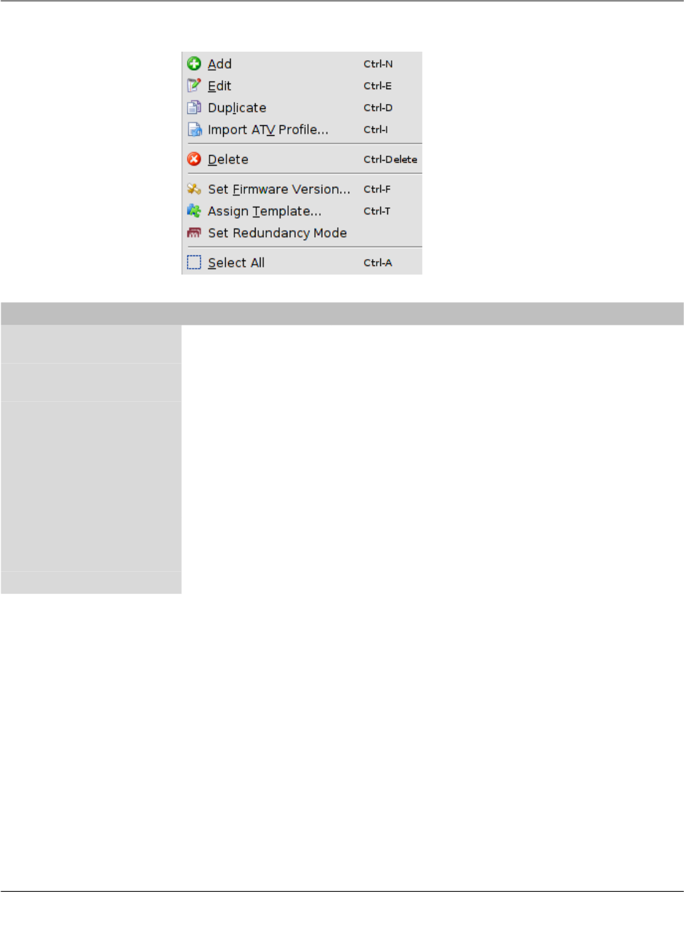
mdm client – Configuration tasks
111024_en_01 PHOENIX CONTACT 67
6.4.2 Template context menu
The following entries are available in the context menu of the template overview table.
Template context menu
Add Create a new template and open the Template properties dia-
log of the new template.
Edit Edit the selected template (only active if exactly one template
is selected in the overview table).
Duplicate To create a duplicate of a template please open the context
menu by clicking with the right mouse button on the template
in the template table. Select Duplicate in the context menu.
mdm will create a copy of the template and append the string
_copy<n> (<n> is a number) to the name of the new template.
Please note that the Duplicate menu entry is only enabled if
exactly one template is selected in the template table.
Import ATV Profile Import an ATV profile into the selected template(s). This works
analogous to the ATV profile import into devices; please refer
to “Device context menu” on page 52 for details.
Delete Delete the selected templates.

FL MGUARD DM UNLIMITED 1.15.x
68
PHOENIX CONTACT 111024_en_01
Set Firmware Version Upgrade the firmware version to a new version.
Since different firmware versions of the mGuard software
have different sets of variables, the firmware version corre-
sponding to the installed firmware on the mGuard has to be
selected here.
Please refer to “Manage firmware upgrades with mdm” on
page 115 for more details.
Assign Template Open the Assign template dialog and assign a parent template
to the selected templates.
Set Redundancy Mode Open a dialog in which redundancy mode can be enabled or
disabled for the selected templates.
Select All Select all templates not excluded by the table filter.
Template context menu
CAUTION: Irreversible changes
Upgrading the firmware version of the device
might change default variable values at the tar-
get version.
It is not possible to downgrade to an older re-
lease. So please be very careful when changing
the firmware version. See “Firmware release
settings and inheritance” on page 78 for more
details.
Once the upgrade has been performed, check
all variable changes at the "Device Configura-
tion History" (see “The configuration history dia-
log” on page 119).
NOTE: New default values in mGuard firm-
ware 8.5 and 8.6
If a default value in the mGuard firmware is
changed, the management of this value in mdm
will be affected:
1. if a firmware version of a managed device
is upgraded to a firmware version with a
changed default value,
2. if a child with a different mGuard firmware
version than its parent inherits a value with
a different default value.
The related behavior of mdm is described in the
Chapter 6.2.1 (“Behavior of changed default
values” on page 42).
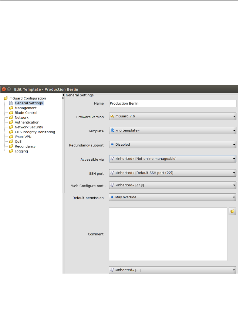
mdm client – Configuration tasks
111024_en_01 PHOENIX CONTACT 69
6.4.3 Template properties dialog
Templates offer a powerful mechanism to conveniently configure and manage a large num-
ber of devices.
By assigning a template to a device (see “Device properties dialog” on page 60), the device
inherits the template settings and will use the values that are defined in the template. De-
pending on the permission settings, the template settings might be overridden in the device
configuration.
Please read this chapter for an introduction to the template concept and refer to “Working
with templates” on page 74 for detailed information on templates and inheritance.
For information on how to create, delete, or edit templates please refer to “mdm main win-
dow” on page 18.
The following screenshot shows the Template properties dialog:
Figure 6-13 Template properties dialog
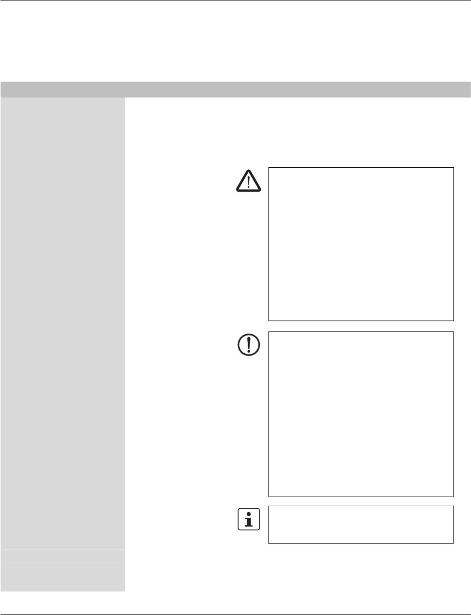
FL MGUARD DM UNLIMITED 1.15.x
70
PHOENIX CONTACT 111024_en_01
General settings Similar to the Device properties dialog (see Chapter 6.3.3) the Template properties dialog
contains a menu corresponding to the mGuard’s Web GUI structure on the left side of the
window.
Additionally the Template properties dialog contains the entry General settings for the
configuration of parameters related to mdm:
Template properties dialog
Name The name of the template.
Firmware version Upgrade the firmware version to a new version.
Since different firmware versions of the mGuard have different
sets of variables, the firmware version (or variable set) the
template should use, has to be selected here.
Template The parent template of this template.
Redundancy support The redundancy support of the device can be enabled or dis-
abled.
CAUTION: Irreversible changes
Upgrading the firmware version of the device
might change default variable values at the tar-
get version.
It is not possible to downgrade to an older re-
lease. So please be very careful when changing
the firmware version. See “Firmware release
settings and inheritance” on page 78 for more
details.
Once the upgrade has been performed, check
all variable changes at the "Device Configura-
tion History" (see “The configuration history dia-
log” on page 119).
NOTE: New default values in mGuard firm-
ware 8.5 and 8.6
If a default value in the mGuard firmware is
changed, the management of this value in mdm
will be affected:
1. if a firmware version of a managed device
is upgraded to a firmware version with a
changed default value,
2. if a child with a different mGuard firmware
version than its parent inherits a value with
a different default value.
The related behavior of mdm is described in the
Chapter 6.2.1 (“Behavior of changed default
values” on page 42).
For more information on how to manage firm-
ware upgrades of your devices with mdm
please refer to Chapter 7.6.

mdm client – Configuration tasks
111024_en_01 PHOENIX CONTACT 71
Accessible via This is the IP address or hostname used by the mdm server to
access the mGuard for an SSH push export of the configura-
tion, an ATV profile import of the configuration or to open the
web interface.
Please refer to “Upload configurations to mGuard devices” on
page 99 for more information on the upload procedure.
The following values are available for Accessible via (the
SSH port and the Web configuration port can be specified
in the fields below.
Not online manageable
The device is not managed via SSH push.
Internal interface in auto stealth mode [1.1.1.1]
mdm accesses the mGuard using the address 1.1.1.1 (ad-
dress of internal interface in automatic stealth mode).
Stealth management address
mdm accesses the external or internal interface of the mGuard
in stealth mode.
First external IP address
mdm accesses the external interface of the mGuard in router
mode.
First internal IP address
mdm accesses the internal interface of the mGuard in router
mode.
Custom value
A custom value (IP address or hostname) might be required to
access the mGuard in NAT scenarios.
SSH port This is the SSH port number used by the mdm server to ac-
cess the mGuard for an SSH push export or an ATV profile im-
port of the configuration.
In some cases it might be necessary to change the standard
SSH port to connect to the device (e.g. the device is not con-
nected to the Internet but gets a port forwarded from the fire-
wall).
If Port for incoming SSH connections is selected, the port
configured in Management >> System Settings >> Shell Ac-
cess >> Shell Access Options>> Port for incoming SSH con-
nections will be used and displayed in the overview table.
Please refer to “Upload configurations to mGuard devices” on
page 99 for more information on the upload procedure.
Template properties dialog

FL MGUARD DM UNLIMITED 1.15.x
72
PHOENIX CONTACT 111024_en_01
Web configuration
port
This is the HTTPS port number used to access the graphical
web interface of the mGuard.
In some cases it might be necessary to change the standard
HTTPS port to connect to the web interface of the device (e.g.
the device gets a port forwarded from the firewall).
If Remote HTTPS TCP port is selected, the port configured
in Management >> Web Settings >> Access >> HTTPS Web
Access >> Remote HTTPS TCP port will be used.
Default Permission The permission mdm uses for variables set to Inherited when
a device or template inherits from this template. The following
permissions can be set:
May override
Variables set to Inherited have May override permission, i.e.
they can be set in the inheriting device or template.
May append
Table variables set to Inherited have May append permission,
i.e. rows can be appended in the inheriting device or template,
but existing rows cannot be changed. Other variables set to In-
herited have May override permission, i.e. they can be set in
the inheriting device or template.
No override
Variables set to Inherited have No override permission, i.e.
they cannot be set in the inheriting device or template.
Comment An additional optional comment which is also shown in the
template table of the main window.
Additional ATV
include
This is a text field for additional settings that should be in-
cluded in the configuration file of the mGuard. The input has to
adhere to the mGuard configuration file conventions. You can
also import the contents of a text file in the field by selecting a
file with the File Chooser icon.
Template properties dialog
Please note that the included configuration will
be appended to the generated mdm settings,
and therefore settings for the same variable in
the include field will override settings generated
by mdm.

mdm client – Configuration tasks
111024_en_01 PHOENIX CONTACT 73
6.4.4 Template configuration
As explained above, the navigation tree on the left side of the Template properties dialog
resembles the mGuard menu structure.
Figure 6-14 shows an example of the configuration for the external interface.
Figure 6-14 Template configuration
Compared to the Device properties dialog there are additional settings in the template con-
figuration which are explained in the following sections.
For detailed information on the template and inheritance concept please refer to “Working
with templates” on page 74.
None value type In the template None can be selected as value, as you can see in the variable IP of internal
interface in Figure 6-14. This means that the template designer does not want to define a
value in the template, but wants to make sure the value is overridden in an inheriting tem-
plate or device. Any attempt to upload a device in which a None value has not been overrid-
den or has been overridden with a Local value results in an error.
Permission setting In Figure 6-14 the variable Netmask of internal network has an additional permission set-
ting. The permission controls whether and how an inheriting device or template can override
the settings. The permission settings can be assigned on a per-variable basis.
Please note that the permission combo box is not visible if Inherited or None is selected
as value.

FL MGUARD DM UNLIMITED 1.15.x
74
PHOENIX CONTACT 111024_en_01
The following permissions can be selected:
6.4.5 Working with templates
Changes made to a template can potentially affect a large number of devices or other tem-
plates. Therefore please keep the following rules in mind when working with templates:
– Before making changes to a variable in a template, make sure that the effect on inher-
iting templates or devices is really desired.
– In particular, changes to a variable permission can have an irreversible effect on inher-
iting templates or devices. E.g. if a permission is changed from May override to No
override, the value of the variable is discarded in all inheriting templates and devices.
– Templates that are still assigned to devices or other templates cannot be deleted.
This chapter gives more detailed information on the template mechanism.
Inheritance Templates are the means to efficiently configure a large number of devices. Templates con-
tain the common aspects of a group of devices or a group of child templates. By assigning
a template to a child (this may be a device or another template) the child “inherits” the parent
template’s settings and may optionally override some of the settings (if the permission in the
parent template allows this). Any change made to the parent template will potentially have
an impact on all inheriting templates and devices, depending on the setting of the value and
permission in the parent template.
The permission setting in a template limits the choices in inheriting templates and devices.
Whether or not a child inherits settings from an ancestor template is indicated by an icon in
front of the variable name in the Properties Dialog. If no icon is shown, then either there is
no template assigned, or the variable has the value Inherited in all ancestor templates, i.e.
no restrictions are defined for this variable.
According to the permissions listed in “Template configuration” on page 73 the following
icons are shown in front of the variable name:
May override.
No override.
May append (tables only).
No value defined (value = None), i.e. the value has to be set in the Device properties
dialog or in one of the intermediate templates.
Template Configuration
Permissions May override The value can be changed (overridden) in an inheriting tem-
plate or device.
No override The value cannot be changed in an inheriting template or de-
vice.
May append This setting is only available for tables (e.g. firewall rules). If a
table variable is set to May append, additional table rows can
be appended in an inheriting device or template, but the inher-
ited rows cannot be changed or removed.
If Local is selected as value and May append as permission,
new entries can be added in an inheriting device or template,
as well as on the mGuard by the netadmin user.
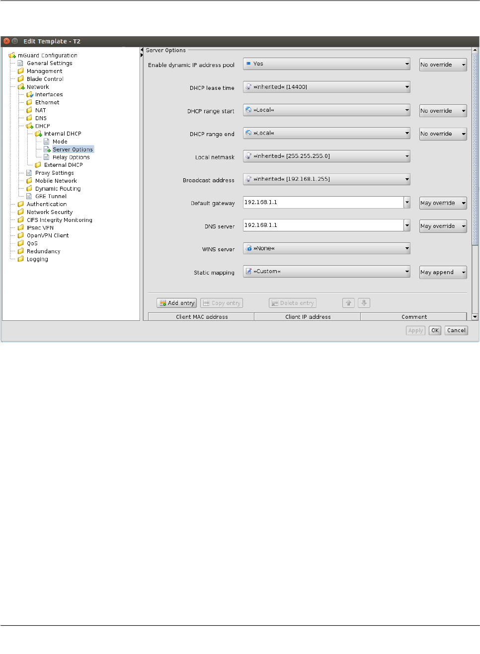
mdm client – Configuration tasks
111024_en_01 PHOENIX CONTACT 75
The following figures illustrate the inheritance mechanism. Figure 6-15 shows the settings
for the DHCP server options in the parent template.
Figure 6-15 Settings in the parent template
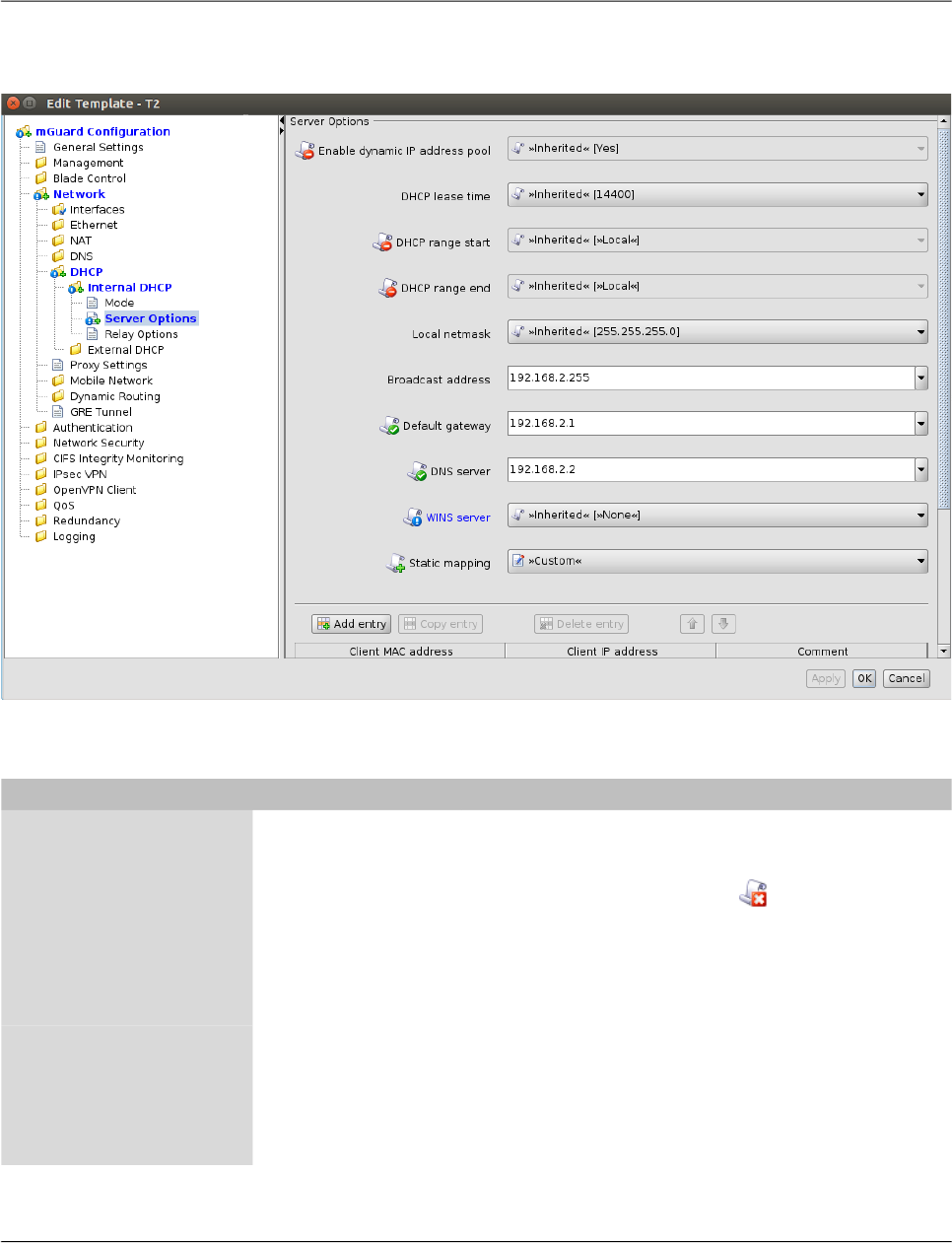
FL MGUARD DM UNLIMITED 1.15.x
76
PHOENIX CONTACT 111024_en_01
Figure 6-16 shows the settings in the device configuration (child). They are the result of
values and permissions inherited from the parent template and modifications made in the
device.
Figure 6-16 Settings in the inheriting device
Settings in the inheriting device
Enable dynamic IP
address pool
This variable is set to Yes in the template and the permission
is set to No override. Therefore the value of the variable can-
not be changed in the device configuration. This is indicated
by the disabled controls and by the icon in front of the vari-
able name in the Device properties dialog.
DHCP range start,
DHCP range end
These variables are set to Local and the permission is set to
No override, i.e. the Local setting cannot be changed in the
device configuration. These values have to be set by the ne-
tadmin of the mGuard and are not managed by mdm.
Local netmask, Broad-
cast address
There are no restrictions for these variables defined in the
template, indicated by the missing icon in front of the variable
name in the Device properties dialog. In the example the de-
vice configurator decided to use a custom value for Broad-
cast address and the (inherited) default value for Local net-
mask.
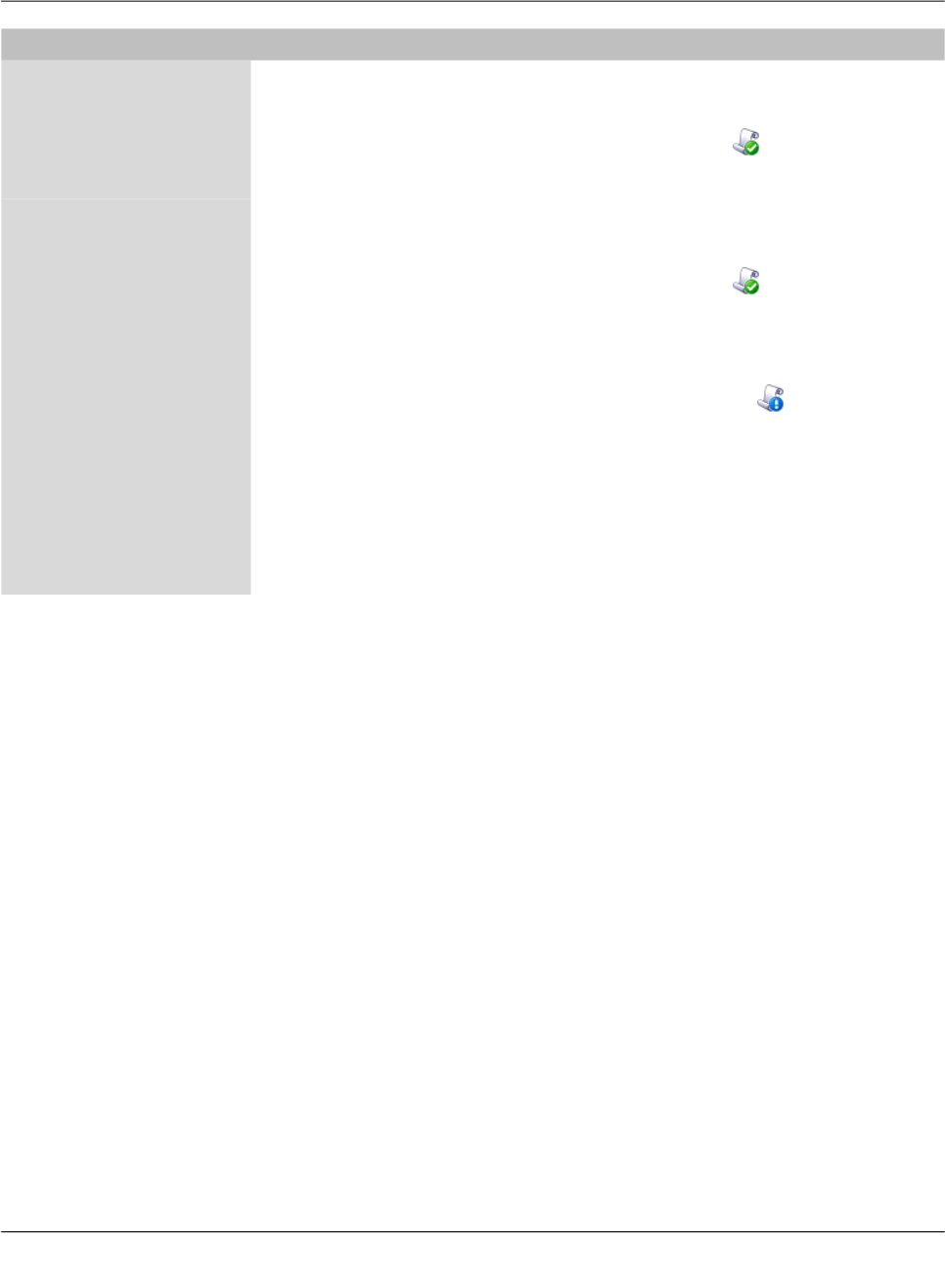
mdm client – Configuration tasks
111024_en_01 PHOENIX CONTACT 77
Default gateway The value of this variable is set in the template and the permis-
sion is set to May override. Therefore the value of the variable
can be changed in the device configuration. This is indicated
by the enabled controls and by the icon in front of the vari-
able name. In the example the value from the template is over-
ridden with a custom value.
DNS server The value of this variable is set in the template and the permis-
sion is set to May override. Therefore the value of the variable
can be changed in the device configuration. This is indicated
by the enabled controls and by the icon in front of the vari-
able name. In this example the value from the template is over-
ridden in the device configuration with a custom value.
WINS server The value of this variable is set to None in the template. There-
fore a value for this variable has to be assigned in the device
configuration. This is indicated by the icon in front of the
variable name and the blue-colored label. If a device for which
None values have not been assigned is uploaded, an error oc-
curs.
Static mapping In the template, the table Static mapping is set to Custom
and its permission is set to May append. As Figure 6-16
shows, rows can be added to the table in the device configu-
ration after switching the table variable to Custom. Rows in-
herited from the template cannot be changed.
Settings in the inheriting device

FL MGUARD DM UNLIMITED 1.15.x
78
PHOENIX CONTACT 111024_en_01
Miscellaneous Complex table variables and permissions
The permission setting for complex table variables (see “General remarks” on page 29) in
the parent template applies to the table itself, but not to the contents of the rows. If the table
is set to No Override, it is not possible to add or delete rows in the child configuration, but
it might be possible to change the value of variables in the inherited rows in the child. Each
variable of a row (node) has a separate permission setting in the parent template that deter-
mines whether the variable can be overridden in the child. The permission setting of the
table and the permission setting of a single variable within the table are completely indepen-
dent.
Firmware release settings and inheritance
Certain restrictions apply to the Firmware Version setting in the General Settings of the
child and the parent template:
– A child cannot inherit from a parent template that has a newer firmware version than the
child itself.
– It is possible to change the firmware version of a parent template to a newer version
only if all children inheriting from the parent template are already set to the new firmware
version.
– The inheritance of changed default values depends on the installed mdm version and
the mGuard firmware version of the device/template (see below).
Inheritance of changed default values
General behavior in mdm < 1.8.0:
If default values (value type = “Inherited“ and not “Local“ or “Custom“) of the child differ from
the default values of the parent (value type = “Inherited“ along the complete inheritance
chain), the inheritance will behave as follows:
1. The child keeps the default values corresponding to the child‘s firmware version. The
value type will remain „
Inherited
“.
General behavior in mdm 1.8.0 or later:
If default values (value type = “Inherited“ and not “Local“ or “Custom“) of the child differ from
the default values of the parent (value type = “Inherited“ along the complete inheritance
chain), the inheritance will behave as follows:
1. Default values that have been changed in mGuard firmware versions < 8.5:
– The child keeps the default values corresponding to the child‘s firmware version.
The value type will remain „
Inherited
“.
2. Default values that have been changed in mGuard firmware versions 8.5 or later:
– The child inherits the default values of the parent. The value type will remain „
In-
herited
“.
Default values have been changed in mGuard firmware 8.5 and 8.6.

mdm client – Configuration tasks
111024_en_01 PHOENIX CONTACT 79
6.5 Configure pools
6.5.1 Pool value overview table
Please select the Pool tab to access the pool overview table. A pool defines a range of net-
work addresses which can be automatically assigned to variables. For detailed information
on pools and their usage please refer to “Pool properties dialog” on page 81.
Figure 6-17 The mdm main window with pool table
Pool table columns The pool overview table contains the following columns.
The column width can be changed by placing the cursor on the header of the
table at the border of two columns and dragging the border to the desired lo-
cation. The order of the columns can be changed by dragging the column
header to a different location.
Pool table columns
Status (
S
) The status icon shows whether the pool definition is valid.
Name The name assigned to the pool.
Comment Optional comment.
Reference count This column shows how many variables reference this pool
(see “Pool properties dialog” on page 81).
Use count This column shows how many values have been used from
the pool (see “Pool properties dialog” on page 81).

FL MGUARD DM UNLIMITED 1.15.x
80
PHOENIX CONTACT 111024_en_01
Filtering and sorting the
table
The header of the table can be used to sort the table entries. A click on a header of a column
will activate the (primary) sort based on this column. This is indicated by the arrow in the col-
umn header. A second click on the same header will reverse the sort order. Clicking on an-
other column header activates the sort based on this new column, the previously activated
column will be used as secondary sorting criterion.
The first row of the table accepts the input of regular expressions (please refer to
Chapter 11, Regular expressions), which can be used to efficiently filter the table entries.
Filtering based on regular expressions is not used for the column that does not contain text
(i.e. column S).
The filter criterion for the three count columns is not interpreted as a regular expression, but
as a comma-separated list of numbers or number ranges
(e.g. 0,2-3).
The filter history will be saved for the current user and can be accessed using the drop down
functionality of the filter fields.
Creating pools There are several ways to create new pools:
1. Open the context menu by clicking on the pool table with the right mouse button. To
open the Pool properties dialog for a new pool please select Add in the context menu.
2. Select the Pool tab and click on the icon in the menu bar to open the Pool proper-
ties dialog for a new pool.
3. Select New » Pool in the main menu to open the Pool properties dialog for a new pool.
Editing pools There are several ways to edit a pool:
1. Double-click with the left mouse button on the pool in the table to open the Pool prop-
erties dialog.
2. Select the pool with the left mouse button and open the context menu by pressing the
right mouse button. Then select Edit to open the Pool properties dialog.
3. Select the pool to be modified in the pool table. Select Edit » Edit Item in the main
menu to open the Pool properties dialog.
Deleting pools There are several methods to delete pools:
1. Select the pool(s) and open the context menu by clicking with the right mouse button.
To delete the pools please select Delete in the context menu.
2. Select the pools to be deleted in the pool table and click on the icon in the menu bar.
Available count This number shows how many values are still available in the
pool (see “Pool properties dialog” on page 81).
Pool table columns
The Edit entry in the context menu and the Edit button in the toolbar are only
enabled if exactly one pool is selected in the pool table.
Please note that pools that are still referenced by variables cannot be delet-
ed.

mdm client – Configuration tasks
111024_en_01 PHOENIX CONTACT 81
6.5.2 Pool context menu
The following entries are available in the context menu of the pool overview table.
6.5.3 Pool properties dialog
The Pool properties dialog allows to define value pools, which can be used to automatically
configure certain variables (e.g. the virtual address for VPNs). Currently mdm allows to de-
fine address range pools (CIDR notation), see below for an example.
Figure 6-18 Pool properties dialog
General settings The entry General settings contains the following parameters for the pool:
Pool context menu
Add Create a new pool and open the Pool properties dialog of the
new pool.
Edit Edit the selected pool (only active if exactly one pool is se-
lected in the overview table).
Delete Delete the selected pools.
Select All Select all pools not excluded by the table filter.

FL MGUARD DM UNLIMITED 1.15.x
82
PHOENIX CONTACT 111024_en_01
Pool properties dialog
General settings Name A name for the pool. This name will be used when referencing
the pool in a variable (see section Pool values usage in vari-
ables below).
Pool type Currently only the pool type IP Networks in CIDR Notation is
available.
Comment A comment (optional).

mdm client – Configuration tasks
111024_en_01 PHOENIX CONTACT 83
Pool definition The entry Pool Definition allows to define the value range of the pool and the address
range of the values to be taken out of the pool. Figure 6-19 contains an example of a pool
definition.
Figure 6-19 Definition of a CIDR pool
The CIDR pool in the example contains all addresses defined in the table Network List. The
field Network Mask defines the range of single values to be taken out of the pool, i.e. when
using this pool in a variable, mdm will automatically assign an IP address range with a mask
of 24 out of the available Source Networks to that variable.
E.g. if the pool is used for the template variable Remote network (in a VPN connection),
then mdm will automatically assign a value to the variable Remote network of all devices
using the respective template. The pool overview table in the main window shows how
many values have been taken out of the pool (Use count) and how many values are still
available in the pool (Available count).
Pool value usage in vari-
ables
Pool values can only be used in templates. For certain variables you can choose the pool
you would like to use from the drop down box, e.g. in Figure 6-20 a number of pools (Lon-
don, New York, Paris, etc.) are available to be used for the variable IP of external interface.
Only pools that match the variable type (e.g. CIDR pool and variable of type IP address) are
shown in the drop down box. If a pool is used in a template, no value is assigned to the re-
Please note that once defined, it is not possible to change or delete the source address
ranges and the network mask in the pool any more, e.g. it is not possible to decrease the
network range 10.12.0.0/16 to 10.12.0.0/19 in the example above. It is only possible to
add further ranges to the pool, i.e. increase the pool value range. Please carefully plan the
definition of the pool ranges in advance.
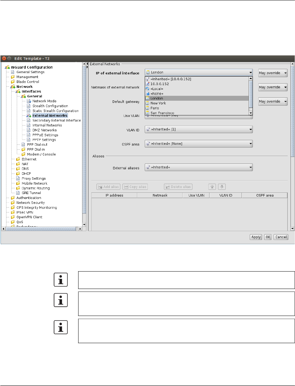
FL MGUARD DM UNLIMITED 1.15.x
84
PHOENIX CONTACT 111024_en_01
spective variable, the pool is only referenced at this point. Therefore the Reference count in
the pool table will be increased by one. If a value is assigned to a variable (which happens
on device level, not on template level) the Use count is increased by one.
This assignment happens automatically if you edit an inherited template of a device by ref-
erencing a pool from a variable to the template or if you assign a template to a device that
already references a pool.
Figure 6-20 Usage of pool values
The following should be kept in mind when working with pools.
In a variable that requires an IP address (not an IP network) only pools with a network
mask of 32 can be referenced.
If you decide to override a pool value in a device, the assigned pool value is not returned
to the pool (i.e. the use count is not decreased), but remains assigned “in the back-
ground”, in case you decide to use the inherited value again.
Pools must be large enough to provide a value for every device that inherits from the tem-
plate in which the pool is referenced, even if some of the devices override their respective
pool value (see above).
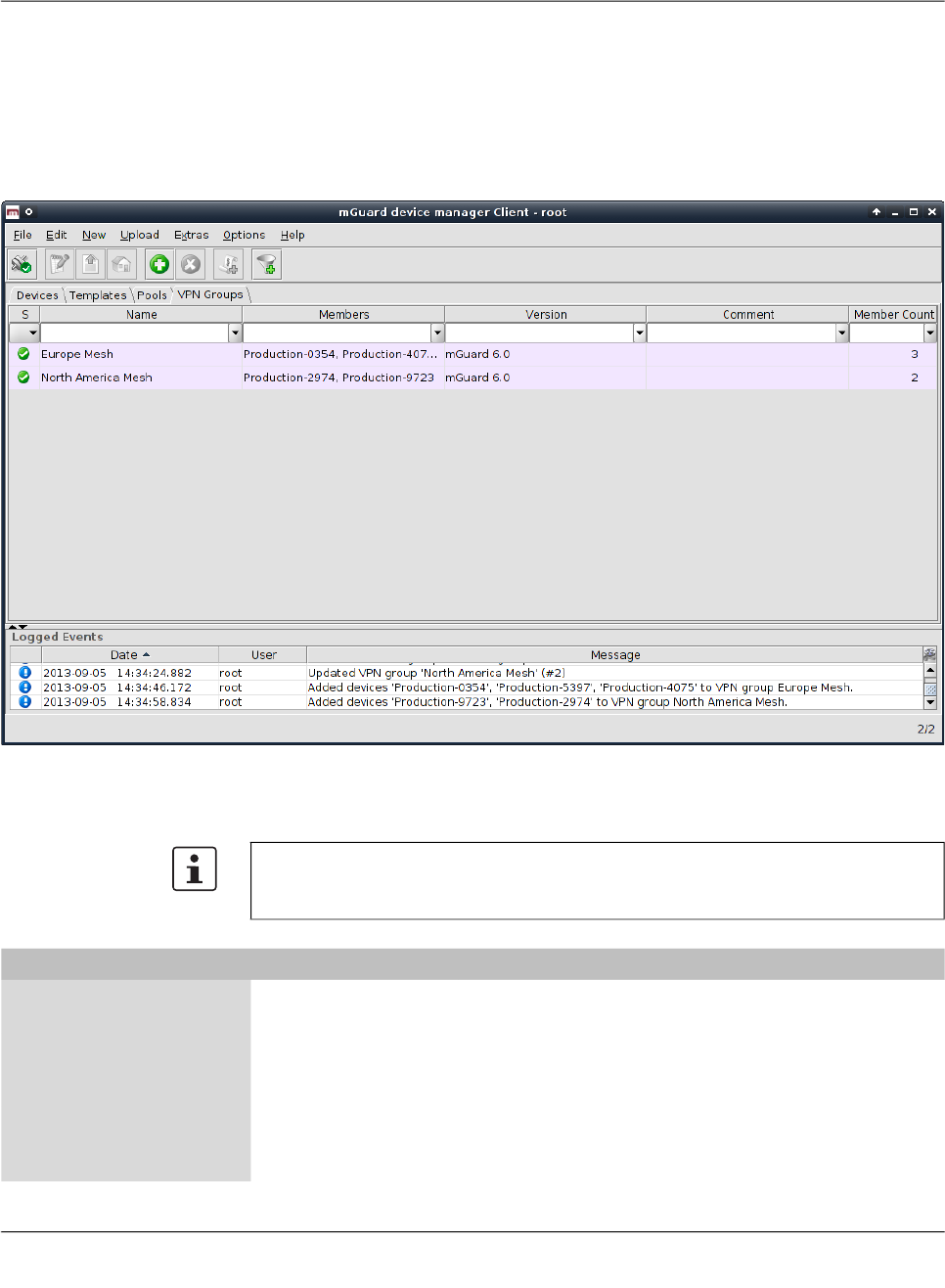
mdm client – Configuration tasks
111024_en_01 PHOENIX CONTACT 85
6.6 Configure VPN groups
6.6.1 VPN group overview table
Please select the VPN Groups tab to access the VPN group overview table. A VPN group
is used to group devices into a meshed VPN network. For detailed information on VPN
groups and their usage please refer to “VPN group properties dialog (Meshed VPN net-
works)” on page 92.
Figure 6-21 The mdm main window with VPN group table
VPN group table columns The VPN group overview table contains the following columns
.
The column width can be changed by placing the cursor on the header of the table at the
border of two columns and dragging the border to the desired location. The order of the
columns can be changed by dragging the column header to a different location.
VPN group table columns
Status (
S
) The status icon shows whether the VPN group is currently
locked.
Name The name assigned to the VPN group. The name can be set in
the General Settings of the VPN group properties dialog (see
Chapter 6.6.4).
Members A comma-separated list of the devices which are members of
the VPN group (i.e. which are a part of the meshed VPN net-
work defined by the VPN group).

FL MGUARD DM UNLIMITED 1.15.x
86
PHOENIX CONTACT 111024_en_01
Filtering and sorting the
table
The header of the table can be used to sort the table entries. A click on a header of a column
will activate the (primary) sort based on this column. This is indicated by the arrow in the col-
umn header. A second click on the same header will reverse the sort order. Clicking on an-
other column header activates the sort based on this new column, the previously activated
column will be used as secondary sorting criterion.
The first row of the table accepts the input of regular expressions (please refer to
Chapter 11, Regular expressions), which can be used to efficiently filter the table entries.
Filtering based on regular expressions is not used for the column that does not contain text
(i.e. column S).
The filter criterion for the Member Count column is not interpreted as a regular expression,
but as a comma-separated list of numbers or number ranges (e.g. 0,2–3).
The filter history will be saved for the current user and can be accessed using the drop down
functionality of the filter fields.
Creating VPN groups There are several ways to create new VPN groups:
1. Open the context menu by clicking on the VPN group table with the right mouse button.
To open the VPN group properties dialog for a new VPN group please select Add in the
context menu.
2. Select the VPN Group tab and click on the icon in the menu bar to open the VPN
group properties dialog for a new VPN group.
3. Select New » VPN Group in the main menu to open the VPN group properties dialog
for a new VPN group.
Editing VPN groups There are several ways to edit a VPN group:
1. Double-click with the left mouse button on the VPN group in the table to open the VPN
group properties dialog.
2. Select the VPN group with the left mouse button and open the context menu by press-
ing the right mouse button. Then select Edit to open the VPN group properties dialog.
3. Select the device to be modified in the device table. Select Edit » Edit Item in the main
menu to open the VPN group properties dialog.
Deleting VPN groups There are several methods to delete VPN groups:
Version The mGuard firmware version that is used for the VPN group.
Comment Optional comment. The comment can be set in the General
Settings of the VPN group properties dialog (see
Chapter 6.6.4).
Member Count This column shows the number of devices which are members
of the VPN group.
VPN group table columns
The Edit entry in the context menu and the Edit button in the toolbar are only
enabled if exactly one VPN group is selected in the VPN group table.
mdm client – Configuration tasks
111024_en_01 PHOENIX CONTACT 87
1. Select the VPN group(s) in the VPN group table and open the context menu by clicking
with the right mouse button. To delete the VPN groups please select Delete in the con-
text menu.
2. Select the VPN groups to be deleted in the table and click on the icon in the menu bar.
Please note that VPN groups that still have member devices cannot be delet-
ed.
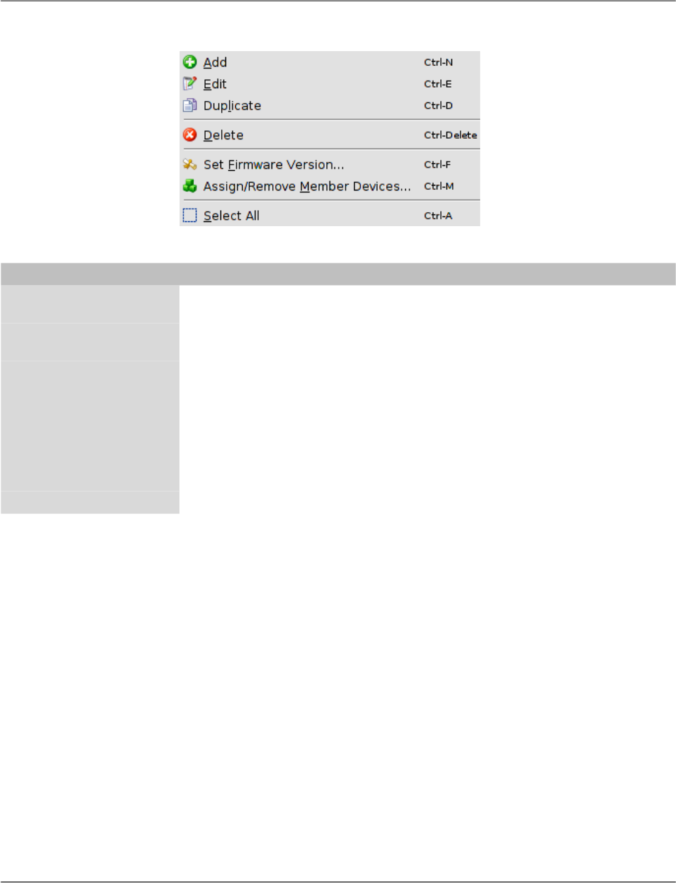
FL MGUARD DM UNLIMITED 1.15.x
88
PHOENIX CONTACT 111024_en_01
6.6.2 VPN group context menu
The following entries are available in the context menu of the VPN group overview table.
VPN group context menu
Add Create a new VPN group and open the VPN group properties
dialog of the new VPN group.
Edit Edit the selected VPN group (only active if exactly one VPN
group is selected in the overview table).
Duplicate To create a duplicate of a VPN group please open the context
menu by clicking with the right mouse button on the VPN
group in the VPN group table. Select Duplicate in the context
menu. mdm will create a copy of the VPN group and append
the string _copy<n> (<n> is a number) to the name of the new
VPN group. Please note that the Duplicate menu entry is only
enabled if exactly one VPN group is selected in the VPN group
table.
Delete Delete the selected VPN groups.
mdm client – Configuration tasks
111024_en_01 PHOENIX CONTACT 89
Set Firmware Version Since different firmware versions of the mGuard software
have different sets of variables, the firmware version corre-
sponding to the installed firmware on the mGuard has to be
selected here.
Assign/Remove Mem-
ber Devices
Edit member devices of one or more VPN groups. Please refer
to “Editing device membership in VPN groups” on page 90 for
more details.
Select All Select all VPN groups not excluded by the table filter.
VPN group context menu
Only devices with a firmware version equal to
or newer than the firmware version of the VPN
group can become its members.
CAUTION: Irreversible changes
It is not possible to downgrade to an older re-
lease. So please be very careful when changing
the firmware version. See “Firmware release
settings and inheritance” on page 78 for more
details.
NOTE: New default cipher values in
mGuard firmware 8.5 and 8.6
If an existing VPN group will be upgraded from
mGuard firmware version < 8.5 to 8.5 or 8.6,
the following applies:
If the table Algorithms in “ISAKMP SA (Key Ex-
change)“ and/or in “IPsec SA (Data Exchange)“
has the default configuration (Encryption), then
the old default cipher value (3DES) will be kept.
In this case the value type of the table will be
changed from “Default“ to “Custom“.
For more information on how to manage firm-
ware upgrades of your devices with mdm
please refer to Chapter 7.6.
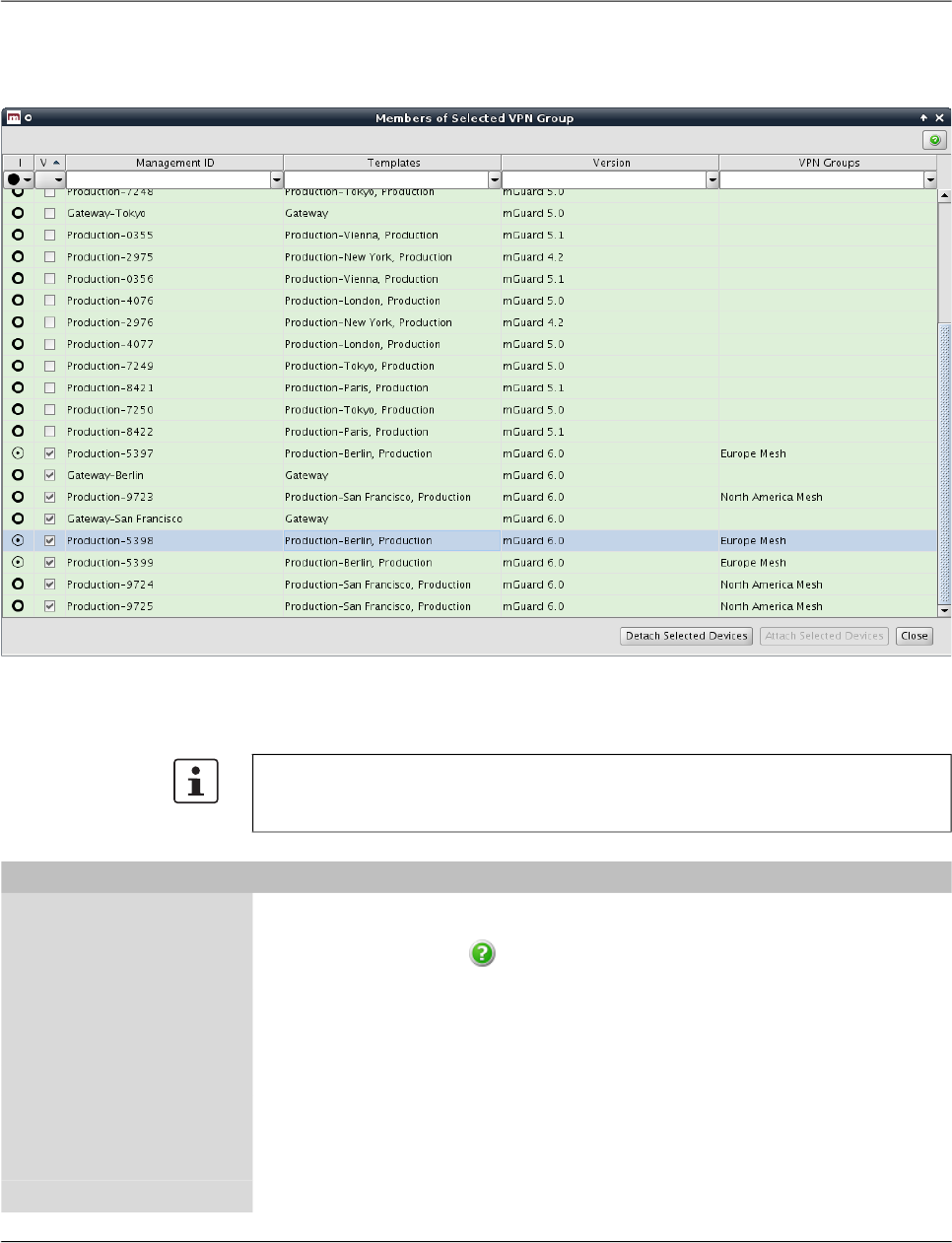
FL MGUARD DM UNLIMITED 1.15.x
90
PHOENIX CONTACT 111024_en_01
6.6.3 Editing device membership in VPN groups
When Assign/Remove Member Devices in the VPN group context menu is activated, a dia-
log opens to edit the device membership of the selected VPN groups:
Figure 6-22 The dialog to edit device membership in VPN groups
VPN group membership
table columns
The VPN group membership table contains the following columns.
The column width can be changed by placing the cursor on the header of the table at the
border of two columns and dragging the border to the desired location. The order of the
columns can be changed by dragging the column header to a different location.
VPN group membership table columns
Status
I
The
I
status icon indicates whether a device is a member of
none, some, or all of the selected VPN groups. Click on the
icon to open a dialog which explains the available icons
and their meanings.
Status
V
The
V
status icon shows whether the firmware version of the
device is compatible with (i.e. equal to or newer than) the firm-
ware version of the selected VPN groups.
Management ID The Management ID of the device.
Templates A comma-separated list of the device’s ancestor templates.
The first item in the
list is the immediate parent template.
Version The firmware version of the VPN group.

mdm client – Configuration tasks
111024_en_01 PHOENIX CONTACT 91
Filtering and sorting the
table
The header of the table can be used to sort the table entries. A click on a header of a column
will activate the (primary) sort based on this column. This is indicated by the arrow in the col-
umn header. A second click on the same header will reverse the sort order. Clicking on an-
other column header activates the sort based on this new column, the previously activated
column will be used as secondary sorting criterion.
The first row of the table accepts the input of regular expressions (please refer to
Chapter 11, Regular expressions), which can be used to efficiently filter the table entries.
Filtering based on regular expressions is not used for the columns that do not contain text
(i.e. columns I and V).
Selecting devices Select the device(s) for which to modify the VPN group membership:
– Click on a device to select it.
– Click on a device, then hold down the Shift key and click on a second device to select
a range of devices.
– Click on a device while holding down the Ctrl key to toggle its selection state.
Assigning or removing
VPN group membership
Click on the Attach Selected Devices button to make the selected devices members of the
selected VPN groups (i.e. the VPN groups that were selected in the VPN group table when
the dialog was opened). Likewise, click on the Detach Selected Devices button to revoke
the membership of the selected devices from the selected VPN groups.
VPN Groups A comma-separated list of VPN groups that the device is cur-
rently a member of.
VPN group membership table columns
A device can only be a member of a VPN group if the device’s firmware version is equal
to or newer than the firmware version of the VPN group.
Any attempt to add a device to a VPN group of which it is already a member, or to remove
a device from a VPN group of which it is not a member, is ignored.
Devices are added to or removed from VPN groups in the background. The dialog can be
closed while the operation is still being performed.

FL MGUARD DM UNLIMITED 1.15.x
92
PHOENIX CONTACT 111024_en_01
6.6.4 VPN group properties dialog (Meshed VPN networks)
The member devices of a VPN group form a meshed VPN network: For each member de-
vice, mdm generates a VPN connection (referred to as a VPN group connection) to every
other member device. A device can be a member of multiple VPN groups. If this results in
multiple VPN connections between the same two devices, mdm generates only one such
connection. VPN groups are not available for firmware versions earlier than 6.0.
The VPN group properties dialog allows to configure common variables used in all VPN
connections within the group.
For information on how to create, delete or edit VPN groups, and how to add or remove
member devices, please refer to “VPN group overview table” on page 85.
Figure 6-23 VPN group properties dialog
Similar to the Device and Template properties dialogs the VPN group properties dialog con-
tains a navigation tree on the left side. It allows you to conveniently navigate to each vari-
able.

mdm client – Configuration tasks
111024_en_01 PHOENIX CONTACT 93
General settings The VPN group properties dialog contains the entry General settings for the configuration
of additional parameters related to mdm. The following parameters can be set in the Gen-
eral settings.
VPN group connections When generating VPN group connections, mdm combines the variables in the VPN group
with additional variables in the device. While the variables in the VPN group are common to
all connections in this group, the additional variables in the device are specific to the device,
but common to all VPN group connections of the device.
The VPN group contains the following variables:
– General VPN settings
– Protocol settings
VPN group properties dialog (Meshed VPN networks)
General settings Name The name is used to identify the VPN group within mdm. It
must be unique.
Firmware Version Since different firmware versions of the mGuard software
have different sets of variables, the firmware version corre-
sponding to the installed firmware on the mGuard has to be
selected here.
Member devices (read
only)
The devices which are currently members of the VPN group.
Comment An optional comment.
Only devices with a firmware version equal to
or newer than the firmware version of the VPN
group can become its members.
CAUTION: Irreversible changes
It is not possible to downgrade to an older re-
lease. So please be very careful when changing
the firmware version. See “Firmware release
settings and inheritance” on page 78 for more
details.
NOTE: New default cipher values in
mGuard firmware 8.5 and 8.6
If an existing VPN group will be upgraded from
mGuard firmware version < 8.5 to 8.5 or 8.6,
the following applies:
If the table Algorithms in “ISAKMP SA (Key Ex-
change)“ and/or in “IPsec SA (Data Exchange)“
has the default configuration (Encryption), then
the old default cipher value (3DES) will be kept.
In this case the value type of the table will be
changed from “Default“ to “Custom“.
For more information on how to manage firm-
ware upgrades of your devices with mdm
please refer to Chapter 7.6.

FL MGUARD DM UNLIMITED 1.15.x
94
PHOENIX CONTACT 111024_en_01
– Authentication settings
– IKE options
Devices and templates contain variables under the IPsec VPN » VPN Group Configura-
tion node which are used when mdm adds VPN group connections to a device:
– Tunnel settings
– NAT settings
– Firewall settings
The local VPN network The local VPN network to be used in VPN group connections can either be specified in the
template or device (IPsec VPN » VPN Group Configuration » Tunnel Settings » Local),
or, if the device is operated in router mode, it can be automatically derived. If the IPsec
VPN » VPN Group Configuration » Tunnel Settings » Use first internal address as
local VPN network in router mode variable is set to Yes, mdm uses the first internal ad-
dress and associated netmask, so that the corresponding local network is visible through
the VPN tunnel. The setting has no effect in stealth mode, i.e. if the device is operated in
stealth mode, the local VPN network must always be specified.
Local 1:1 NAT VPN group connections can be configured to perform 1:1 NAT on local addresses. None of
the other NAT mechanisms for VPN connections are available in VPN group connections.
Local 1:1 NAT is enabled by setting the IPsec VPN » VPN Group Configuration » NAT »
Enable 1:1 NAT of local addresses variable to Yes. The local network within the tunnel
must be specified.
Extended firewall rules The firewall rules under the IPsec VPN » VPN Group Configuration node contain addi-
tonal Combine fields associated with the From IP and To IP addresses or networks. If a
Combine field is set to No, the corresponding address or network is used in the VPN group
connection without modification.
If a Combine field is set to Yes, the address or network entered in the table is combined
with the local or remote VPN network to calculate the network used in the VPN group con-
nection.
– In the incoming firewall rules, the From IP field is combined with the remote VPN net-
work and the To IP field is combined with the local VNP network.
– In the outgoing firewall rules, the From IP field is combined with the local VPN network
and the To IP field is combined with the remote VNP network.
The value of the From IP or To IP field is combined with the VPN network by adding the
addresses octet-wise, i.e. each octet is added individually. If the result of adding two octets
overflows (i.e if it is greater than 255), the value 256 is subtracted (i.e. the addition “wraps
around”). The network mask of the value of the From IP or To IP field (or 32 if the field does
not contain a network mask) is applied to the result.
Examples:
– If the From IP or To IP field has the value 0.0.78.0/24, and the VPN network is
10.6.0.0/16, the combined value is 10.6.78.0/24.
– If the From IP or To IP field has the value 0.1.78.0/24, and the VPN network is
10.6.0.0/16, the combined value is 10.7.78.0/24.
Please note that the network within the tunnel (i.e. the network addresses as seen by the
peer) is specified in the 1:1 NAT settings. This is different from the mGuard Web GUI
where the network outside of the tunnel (i.e. the network addresses as seen from the local
network) is specified in the 1:1 NAT settings.
mdm client – Configuration tasks
111024_en_01 PHOENIX CONTACT 95
6.7 Configure VPN connections
With mdm you can easily generate the configuration for a large number of VPN tunnels. In
general, the information contained in Chapter 6.1, Chapter 6.3.3, Chapter 6.4.3 and
Chapter 6.4.5 applies also to the VPN configuration.
But VPNs require some special settings to be taken into consideration, which are explained
in this chapter, e.g. the automatic configuration of the VPN peer. You can find the VPN con-
figuration in the node IPsec VPN of the navigation tree.
Adding and editing VPN
connections
To add, change or delete VPN connections, please open the node IPsec VPN » Connec-
tions. To create a new connection, create a new table row (see “Modifying mGuard table
variables” on page 38). As soon as you create a connection, it appears as node in the nav-
igation tree. To edit the connection, open its node in the navigation tree and navigate to the
desired settings. The structure of the connection node resembles the menu structure on the
mGuard.
Automatic configuration
of the VPN peer
You can automatically generate the VPN configuration for the peer device (see
Figure 6-24): Place the cursor in the field Peer device and press the Cursor Down key. A
list of available devices appears. You can limit the number of devices in the list by entering
the first characters of the Management ID of the desired device. If you select a device, the
VPN configuration for this device will be automatically generated.
The connection table is read-only, i.e. you have to navigate to the respective node to
make changes to the connection, e.g. change the name of the connection or disable a
connection.
Please note that the permission setting of the connection table in a template applies to the
table only, and not to the contents of the connections. If you set the table to No override,
the settings of the VPN connection can still be modified on a device which uses this tem-
plate, but the user on the device level is not allowed to add further connections to the ta-
ble.
Not all settings of the peer can be automatically generated, therefore you have to enter
parts of the configuration manually. Please check the sub-nodes of the VPN connection
for those settings, they are in the relevant subnodes separated from the other settings by
the text Configuration of peer device (for an example see Figure 6-24).
The automatically generated VPN connections show up as read-only in the peer connec-
tion table, i.e. you cannot change the configuraton on the peer side.
If the VPN gateways have different firmware versions the configuration of a peer is only
possible in the Properties Dialog of the device with the older firmware version. If you con-
figure the peer in the Properties Dialog of the device with newer firmware the connection
will not be generated in the device with the older firmware. There will be no error or warn-
ing displayed.
The automatically generated VPN connections can be used as alternative to the mGuard
Tunnel Group feature (mGuard 5.0 or later), see comments in section Hints for VPN con-
figurations below.

FL MGUARD DM UNLIMITED 1.15.x
96
PHOENIX CONTACT 111024_en_01
Figure 6-24 Automatic configuration of VPN peer
Setting VPN identifiers au-
tomatically
The local and the remote machine certificate are known to mdm in many typical usage sce-
narios (when VPN configuration for the peer device is generated by mdm). mdm can make
use of this information to set the Local VPN Identifier and the Remote VPN Identifier vari-
ables automatically, i.e. derive the identifiers from the known certificates. It is necessary to
set these variables when CA certificates are used to authenticate VPN connections.
To make use of this feature, open the IPsec VPN » Connections » Connection Name »
Authentication » VPN Identifiers node and set the variable Set VPN Identifiers auto-
matically to yes. In this mode, the Local VPN Identifier and the Remote VPN Identifier
variables are ignored; the identifiers are derived from the cerificates.
Copying firewall rules The firewall tables within VPN connections contain a Copy from Main button. Clicking this
button copies the content of the corresponding firewall table for non-VPN traffic (i.e. if the
current firewall table is for incoming traffic, the incoming firewall table for non-VPN traffic is
copied; likewise for outgoing traffic).
A separate background color is used to indicate which firewall rules have been copied. The
background color is cleared once a different navigation tree node is opened.
mdm client – Configuration tasks
111024_en_01 PHOENIX CONTACT 97
Hints for VPN configura-
tions
These hints are useful if the tunnel group feature is not used and the VPN connections are
explicitly defined.
In 1:N VPN configurations it is recommended to define the VPN connection in a template
and select the central device in the Peer device field (See section Automatic configura-
tion of peer above). If you assign this template to the devices mdm will automatically gen-
erate the N connection configurations for the central device.
In a 1:N VPN configuration it is required for the configuration of the peer to specify the
gateway address of the current device (see Figure 6-24, Configuration of peer device »
Gateway address of peer). If certificates are used %any (as shown in Figure 6-24) can
be used as address in the template, but if PSK authentication is used, %any is not al-
lowed. If PSK authentication is used, the external address (if no NAT us used) has to be
entered into the field Configuration of peer device » Gateway address of peer for
each device.

FL MGUARD DM UNLIMITED 1.15.x
98
PHOENIX CONTACT 111024_en_01
mdm client – Management tasks
111024_en_01 PHOENIX CONTACT 99
7 mdm client – Management tasks
7.1 Upload configurations to mGuard devices
7.1.1 Upload methods
You have the following options to initiate an upload of the configuration to the devices:
– Open the menu Upload in the main menu (Chapter 5.2.1) and select which devices
should be uploaded (All, Selected or Changed, i.e. all devices in mdm, corresponding
to mGuards with a configuration status of out-of-date).
– Select the entry Upload in the context menu (right-click on the device table). This will
schedule all currently selected devices in the device table for upload.
– Click on the icon in the tool bar to initiate an upload for the currently selected devic-
es in the device table.
mdm offers several methods to upload the configuration files to the mGuards. After initiating
the upload, please specify which upload method you prefer.
Auto Depending on whether or not Accessible via in General settings is set, mdm will either
perform
– an SSH push upload (see “Upload via SSH” ) or
– an export of the configuration to the file system (see “Prepare pull configuration” )
Upload via SSH mdm tries to upload all scheduled devices by using an SSH push upload.
The mdm server accesses the mGuards using the SSH protocol. Subsequently the config-
uration file is copied to the device and put into operation. Any failures during the upload pro-
cess are shown in the log window. To use this method the following requirements have to
be met:
– In the General Settings of the Device properties dialog an IP address or a hostname
has to be set for the field Accessible via. The SSH port number can be set optionally.
– The mGuard has to be accessible from the mdm server using the Accessible via ad-
dress, i.e. a firewall must not block the traffic and a NAT device in the communication
path has to be configured appropriately to allow the communication between the mdm
server and the mGuard.
– In case the mGuard is accessed on the external interface, the SSH remote access has
to be enabled on the mGuard.
For an SSH upload, an IP address or a hostname has to be specified in the
field Accessible via in the General settings of the Device properties dialog
(see Chapter 6.3.3). If this is not the case, an error will be displayed in the log
window and the upload status will be set to error. An SSH port number (dif-
ferent from the standard SSH port 22) can be set optionally.
If mdm cannot login to the device due to wrong SSH authentication informa-
tion, an error will be displayed in the log window and the upload status will be
set to error.
If the mGuard is not accessible, mdm will retry to upload the configuration. Af-
ter the maximum retry count is reached an error message will be displayed in
the log window and the upload status will be set to error.
FL MGUARD DM UNLIMITED 1.15.x
100
PHOENIX CONTACT 111024_en_01
– The passwords to access the device have to be set correctly. For uploading the device
configuration to the mGuard, mdm logs in as user
admin
. In case of a password change
there are 2 passwords involved: the old password, which is used to access the device
and the new password, which will be set after logging in. Therefore mdm automatically
keeps track of the active password to be used to access the device and does not use
the password configured in the Device properties dialog for this purpose. If you would
like to manually change the active password you can use the option Set Current De-
vice Credentials in the context menu of the device table.
Prepare pull configuration The configuration of all scheduled devices will be exported to the file system.
The mGuards are able to pull configuration files from an HTTPS server. mGuards running
firmware version 5.0 or later can additionally pull license files.
To use the configuration pull feature, please refer to the section Manual configuration up-
load above for a description how to export configuration and license files. Additionally the
following requirements have to be met:
– An HTTPS configuration pull server has to be configured (see Chapter 3.2).
If a device is not accessible, mdm will retry the connection after a waiting time. As soon
as the maximum count of retries is reached mdm will stop trying to upload the configura-
tion and will show an error in the log.
If a configuration change causes the mGuard to reboot (e.g. when switching from stealth
to router mode), mdm is not immediately informed whether the configuration has been
successfully applied. It will therefore reaccess the device after a waiting time. Adapt the
Accessible via, SSH port and Web configuration port settings after the initial upload
if necessary (see “Accessible via” on page 62). Alternatively the configuration state can
be set manually with the option Set Upload State in the context menu of the device over-
view table.
If you change the password in the Device properties dialog and a subsequent upload of
the device configuration fails, it may happen that the password change was applied on the
mGuard but mdm was not able to keep track of the successful change. In this case you
have to manually set the active password in mdm using the option Set Current Device
Credentials in the context menu of the device overview table, otherwise mdm will not be
able to log in for the next upload.
Due to this potential issue it is recommend to apply (upload) password changes separate-
ly from extensive configuration changes.
The export directory can be configured in the preferences file of the server (see
Chapter 10.1).
The filename for each configuration file is shown in the General settings of the Device
properties dialog and in the device table.
In case the files cannot be written to the file system (no permission, disk capacity exceed-
ed, export directory not existent, etc.), mdm displays an error in the log and the upload
status will be set to error.
mdm client – Management tasks
111024_en_01 PHOENIX CONTACT 101
– The configuration pull has to be configured on the mGuards (please refer to the Refer-
ence Manual mGuard Firmware).
Additionally the mGuards have to be configured with the 2 following commands to pull
their configuration according to the mdm file name convention:
gaiconfig --set GAI_PULL_HTTPS_DIR <your_directory>
gaiconfig --set GAI_PULL_HTTPS_FILE <identifier>.atv
– In case that the mdm server and the configuration server are installed on different ma-
chines you have to make sure that the mdm export files are synced to the file system of
the configuration server.
– If mdm is installed manually, additional steps are necessary if you would like to get a
feedback whether or not the configuration pull was successful.
– mdm is able to receive Syslog messages on port UDP 7514 (default) in order to detect
the configuration status of a device if mdm is configured as Syslog server in the config-
uration server settings.
Profile encryption
Configuration profiles exported by the mdm server can optionally be encrypted with a de-
vice-specific key. The mdm server downloads the key from the license server. Only the pub-
lic (encryption) key is known to Phoenix Contact; the corresponding private (decryption) key
is stored within the mGuard in a special hardware module and cannot be extracted.
Profile encryption can only be used with mGuard hardware that supports this feature. Firm-
ware version 7.6.0 or later is required.
Follow these steps to encrypt profiles:
– Obtain a user name and password to download profile keys from Phoenix Contact sup-
port. Configure the mdm server to use the "username" and "password"; see
Chapter 10.1, nodes license » licenseServer » reqUsername and license »
licenseServer » reqPassword.
– Select the devices for which to encrypt profiles in the device overview table.
– Select the menu entry Get Profile Key in the context menu to download the keys to the
mdm server. The serial numbers and flash IDs of the devices are used to identify them
to the licsense server and must therefore be known to mdm; set them if necessary.
– Select the menu entry Enable/Disable profile encryption in the context menu to enable
profile encryption.
The pull request contains information about the current configuraton status of the
mGuard. This information will be sent as Syslog message from the configuration server to
mdm. The port on which mdm listens for Syslog messages can be configured in the pref-
erences file of the mdm server (see Chapter 10.1).
Since profiles are encrypted with a device-specific key, only the mGuard for which the
profile has been encrypted can read it.

FL MGUARD DM UNLIMITED 1.15.x
102
PHOENIX CONTACT 111024_en_01
Manage Profile Keys
The profile keys needed for profile encryption are listed in the table. New profile keys can
be imported. Existing profile keys can be deleted.
Prepare pull configuration
and try ssh upload
To update devices that are manageable online via ssh push upload and to update (export)
their pull configuration at once, this method can be used.
The mdm will perform the following tasks:
1. Prepare the pull configuration as described above (see “Prepare pull configuration” ) for
all selected devices.
2. Check, if an IP address or a hostname has been specified in the field Accessible via
in the General settings of the Device properties dialog (see “Device properties dialog”
on page 60) for each of the selected devices.
3. For those selected devices for which an IP address or a hostname has been specified,
an SSH push upload to the selected device(s) will be performed (see “Upload via SSH” ).
Manual configuration
up-load
In case there are only a few devices to be configured and the devices cannot be accessed
by mdm, it is possible to export the configuration files to the file system and upload them
manually to each device using the Web GUI of the respective device. Each device is iden-
tified by a unique identifier which is automatically assigned by mdm. This identifier (8-digit
hex string with lower case characters) is used as file name for the export. The convention
for the exported configuration file is: <identifier>.atv. The filename for each configuration file
is shown in the General settings of the Device properties dialog and in the device table.
To export configuration files the following requirements have to be met:
– An export directory has to be configured in the preferences file of the mdm server (see
Chapter 10.1). Please note that it is not possible to export the files locally on the client
side. The files are always exported on the server side to the export directory configured
in the server preferences file.
– The export directory has to be accessible and writeable from the server.
– There has to be enough disk space to export the files.
7.1.2 Upload time
The time when upload should be performed. Times are specified as an ISO date (YYYY-
MM-DD where YYYY is the year, MM is the month of the year between 01 and 12, and
DD is the day of the month between 01 and 31) optionally followed by an ISO time
(hh:mm:ss where hh is the hour according to the 24-hour timekeeping system, mm is the
minute and ss is the second). For example, a quarter past 4 p.m. and 20 seconds on
December 22nd, 2010 would be written as 2010-12-22 16:15:20. Alternatively, click on the
icon to select the date from a calender.
If the current time (which is the default value) or a time in the past is specified, the upload
is performed as soon as possible.
The Upload within … minutes after field is used to specify an upper bound on the time
frame in which mdm will attempt to perform the upload. If it does not succeed within the
specified time, mdm will perform no more upload attempts and consider the upload failed.
mdm client – Management tasks
111024_en_01 PHOENIX CONTACT 103
7.1.3 Temporary upload password
If a password is entered into this field, and a push upload is performed, mdm uses this pass-
word when logging into the mGuard via SSH. The password is used for all devices. If the
field is left empty (default), mdm uses the known admin password of each device.
When a temporary upload password is used, mdm can use a user name other than admin
to log into the mGuard. This user name can be configured in the Device properties dialog or
the Template properties dialog. Please open the „Authentication » Local Users » Tem-
porary Upload User“ node in the navigation tree.
7.1.4 Upload history
Shows the upload history. The upload history contains details on the last upload actions and
their results for each device. To review the upload history for a device, please select the
mGuard in the device overview table and open the context menu with a click with the right
mouse button. Select Upload History to open a window with the upload history.
The feature is useful if the mGuard does not use the configured admin password to au-
thenticate the login request, e.g. if the mGuard uses RADIUS authentication.

FL MGUARD DM UNLIMITED 1.15.x
104
PHOENIX CONTACT 111024_en_01
7.2 Manage license vouchers and device licenses
mdm enables you to centrally manage your license vouchers and device licenses. The main
menu contains two entries: Licenses » Manage Device Licenses and Licenses » Man-
age License Vouchers which are explained in detail in the following sections.
7.2.1 Manage license vouchers
To open the Voucher Management Window please select Licenses » Manage License
Vouchers from the main menu.
Figure 7-1 The Voucher Management Window
The window shows the available number of vouchers per voucher type. To import vouchers
either paste the voucher information into the import field, or select a file that contains the
voucher data and then click on Import. Only CSV is supported as import format, i.e. each
line of the import data has to contain the following information:
<voucher number>,<voucher key>
7.2.2 Request/generate licenses
At least one voucher of the corresponding type (major release upgrade, VPN etc.) has to be
imported into mdm before requesting a device license. Furthermore the serial number is re-
quired for the license request, i.e. the number has to be supplied in the General Settings
of the device. This identification number may be entered manually or is automatically re-
quested from the device during the push or pull upload procedure.
To request licenses, select the devices in the device overview table and either press the
icon in the tool bar or select Generate License from the context menu. The generated li-
censes are subsequently shown in the License Management Window and on the

mdm client – Management tasks
111024_en_01 PHOENIX CONTACT 105
Management » Licensing page in the Device properties dialog and will be installed on the
device with the next upload. The result of the license request is also shown in the log win-
dow.
7.2.3 Manage device licenses
To open the License Management Window please select Licenses » Manage Device Li-
censes from the main menu. All licenses managed by mdm and their licenses details are
shown in the License Management Window. In addition to license requested/generated by
the procedure described in the previous section, existing licenses can be imported. To im-
port licenses either type or paste the filenames of the license files (one filename per line)
into the import field and click on Import subsequently, or click on the Choose File button
and select one or more files in the dialog.
Figure 7-2 The License Management Window
mdm has to be able to connect to the license server in order to generate/request licenses.
A double-click on a license (row) in the table opens the Device properties dialog of the cor-
responding device (if any).
All licenses managed by mdm will be installed on the devices with every upload.
The licenses are automatically assigned to the devices by using the serial number con-
tained in the license, i.e. without a serial number in the General settings of the device an
assignment of the licenses is not possible.

FL MGUARD DM UNLIMITED 1.15.x
106
PHOENIX CONTACT 111024_en_01
7.2.4 Refresh licenses
To refresh all licenses in mdm for a device you can select the option Refresh Licenses in
the context menu of the device overview table. mdm will contact the license server and re-
trieve all licenses that were bought for this device. The licenses will be installed with the next
configuration upload. You can use this option, if you accidentally deleted licenses in mdm
or if you would like to manage an mGuard that has already licenses installed that are not yet
managed by mdm.

mdm client – Management tasks
111024_en_01 PHOENIX CONTACT 107
7.3 Manage users, roles, and permissions
The permission to log into the mdm client, and the permission to perform certain operations
once logged in, are controlled through users and roles. A user corresponds to a person log-
ging into the mdm client. Each user has one or more associated roles, and each role has an
associated set of permissions. The union of all permissions associated with a user’s roles
determine what permissions are granted to a user.
User and role manage-
ment
Users, roles and permissions are managed in the Users and Roles Dialog, which is opened
through the Extras » Manage Users and Roles menu entry:
Figure 7-3 The users and roles dialog
The dialog consists of three panels, the Users Panel, the Roles Panel, and the Permissions
Panel.
The permissions are granted when a user logs in, and remain valid until the user logs out.
Therefore, any modifications to the user, role, or permission configuration have no imme-
diate effect on logged in users.
The Users Panel does not appear if RADIUS authentication is used; please refer to
Chapter 7.3.4 for more details. The buttons to modify users or roles do not appear if the
user opening the Users and Roles Dialog does not have the permission to modify users
and roles.

FL MGUARD DM UNLIMITED 1.15.x
108
PHOENIX CONTACT 111024_en_01
7.3.1 Manage users
Users are managed in the Users Panel of the Users and Roles Dialog. They can be added
with the Add button, deleted with the Delete button, and edited with the Edit button or by
double-clicking on the user in the table. The following data must be specified when adding
or editing a user:
– Username: The username which the user uses to log into the mdm client. Usernames
must be unique.
– Real Name: The Real Name has no technical effect; its purpose is to make it easier to
associate a user with a real person.
– Password: The user must provide the correct password to log into the mdm client.
Assigning roles to users If one or more users in the Users Panel and one or more roles in the Roles Panel are se-
lected, the roles can be assigned to the users by clicking the Assign Role button or re-
moved by clicking the Remove Role button. All of the selected roles are assigned to or re-
moved from all of the selected users.
The superuser root A “superuser” with the user name root always exists. Although it has no associated roles, it
has all permissions (i.e. it is treated specially by mdm). The superuser cannot be deleted,
nor can permissions be revoked from the superuser.
Initial users Three users exist in a fresh mdm installation, root, admin, and audit. The initial password of
each of these users is identical to the respective user name.
Resetting the root pass-
word
If the password for the superuser root is lost, it is possible to reset it to root with the following
psql command (to be performed while the mdm server is not running):
UPDATE mgnt_system_users SET "password" = 'WNd6PePC4QrGiz2zeKv6bQ=='
WHERE "username" = 'root';
7.3.2 Manage roles
Roles are managed in the Roles Panel of the Users and Roles Dialog. They can be added
with the Add button, deleted with the Delete button, and edited with the Edit button or by
double-clicking on the role in the table. Each role has a name which must be unique.
Assigning permissions to
roles
If one or more roles in the Roles Panel and one or more permissions in the Permissions
Panel are selected, the permissions can be assigned to the roles by clicking the Grant Per-
mission button or removed by clicking the Revoke Permission button. All of the selected
permissions are assigned to or removed from all of the selected roles.
Initial roles Two roles exist in a fresh mdm installation, admin, and audit. The admin role has all permis-
sions except modification of users and roles. The audit role has read permissions, but no
modification permissions.
Once a Username has been set, it can not be edited anymore.

mdm client – Management tasks
111024_en_01 PHOENIX CONTACT 109
7.3.3 Permissions
The permissions table in the Permissions Panel of the Users and Roles Dialog lists all avail-
able permissions. The permissions grant the following actions:
Minimal permission set The permissions Read Devices, Read Templates, Read Pools, and Read VPN Groups form
the minimal permission set. These permissions cannot be revoked from a role.
Filtering the permission
table
The columns U and R show how each permission relates to the currently selected users and
roles. They can be used to filter the permission table.
The following icons can appear in the U column:
The permission is not granted to any of the selected users.
The permission is granted to some (but not all) of the selected users.
The permission is granted to all of the selected users.
Permission Granted Actions
Read Devices View the list of devices, device configurations, device li-
censes, and license vouchers.
Write Devices Edit, add, remove, or duplicate device configurations; add
or remove device licenses; add license vouchers.
If the user has the Read Configuration History permission
in addition to this permission: Reconstruct devices from de-
vice configuration history entries.
Upload
Device Configuration
Initiate the upload of configurations to devices or the export
of pull configuration files.
Read
Configuration History
View and compare device configuration history entries.
If the user has the Write Devices permission in addition to
this permission: Reconstruct devices from device configu-
ration history entries.
Read Templates View the list of templates and template configurations.
Write Templates Edit, add, remove, or duplicate template configurations.
Read Pools View the list of pools and pool configurations.
Write Pools Edit, add, or remove pool configurations.
Read VPN Groups View the list of VPN groups and VPN group configurations.
Write VPN Groups Edit, add, remove, or duplicate VPN group configurations.
Read Users and Roles View users, roles, and permissions.
Write Users and Roles Manage users, roles, and permissions (including the per-
mission to set other user’s passwords).
Read Event Log View the persistent event log.

FL MGUARD DM UNLIMITED 1.15.x
110
PHOENIX CONTACT 111024_en_01
Likewise, the same icons are used in the R column to express if the permission is assigned
to none, some, or all of the selected roles.
7.3.4 User authentication
mdm supports two mechanisms to authenticate users logging into the mdm client, the mdm
database and RADIUS.
mdm database authenti-
cation
Authentication against the mdm database is the default mechanism. It uses the user names
and passwords stored in the mdm database and configured in the Users Panel of the Users
and Roles Dialog to authenticate users. Please refer to Chapter 7.3.1 for more details.
RADIUS authentication Remote Authentication Dial In User Service (RADIUS) is a network protocol that provides
a remote authentication service. If the mdm server is configured to use RADIUS authentica-
tion, the users stored in the mdm database are ignored. When a user attempts to log into
the mdm client, the mdm server performs a request to one or more RADIUS servers to au-
thenticate the user. The RADIUS reply must contain one or more Filter-Id attributes which
the mdm server interprets as role names. If the login attempt is sucessful, the user is as-
signed to the roles specified in the Filter-Id attributes.
Please refer to Chapter 10.1 for more information on how to configure the mdm server to
use RADIUS authentication.
If RADIUS authentication is used, mdm does not use the concept of a superuser. The user
name root is not treated specially in any way.

mdm client – Management tasks
111024_en_01 PHOENIX CONTACT 111
7.4 Manage X.509 certificates
The functionality of the certificate management depends on the mGuard release. Beginning
with mGuard firmware release 5.0 it is possible to:
– manage multiple machine certificates (prior to release 5.0 only one machine certificate
was supported)
– manage CA certificates (prior to release 5.0 CA certificates were not supported)
– manage connection certificates at a central location (prior to 5.0 the connection certifi-
cate was part of the VPN connection only; beginning with 5.0 the connection certificates
can be managed centrally and then be referenced for SSH or HTTPS authentication)
– manage CRLs (prior to release 5.0 CA CRLs were not supported)
Exporting Certificates You can export certificates, e.g. if you would like to use the machine certificate as connec-
tion certificate for a VPN connection. To export a certificate please navigate to the respec-
tive certificate table (see below for more information) and click on the Export button. You
can export the certificate to a folder of your choice.
7.4.1 Machine certificates
You can either import a machine certificate (PEM or PKCS#12 file), request a certificate
from the mdm CA, request a certificate from any CA supporting the Simple Certificate En-
rollment Protocol (SCEP), or manually enrol certificates.
Requesting a machine cer-
tificate
Prior to requesting a certificate make sure that the certificate attribute fields contain the de-
sired values (for mGuard firmware 4.2 navigate to IPsec VPN » Global » Machine
certificate » Certificate attributes, for mGuard firmware 5.0 or later navigate to
Authentication » Certificates » Certificate settings and Certificate attributes).
To request a certificate select one or more devices in the device overview table and select
Certificate Handling » Request Additional Certificate or Certificate Handling » Re-
quest Replacement Certificate from the context menu. The difference is that Request
Additional Certificate will append the new certificate to the list of existing certificates while
Request Replacement Certificate will replace the existing certificates with the new one,
so that the device ends up with a single machine certificate.
In a template it is not possible to request or import a machine certificate. (It is only possible
to import the connection certificate of the peer).
The file to be imported can be in PEM format containing the unencrypted private key and
the certificate, or in PKCS#12 format protected by a password (the PKCS#12 file is only
allowed to contain the “machine“ certificate and not an additional CA certificate). The file
type is automatically detected. When importing a PKCS#12 file, a dialog asking for the
password is displayed.
You can convert a PKCS#12
file to PEM using the command:
openssl pkcs12 -in inputfile.p12 -nodes -out outputfile.pem .
When SCEP is used, the CA server must be configured to issue certificates immediately.
Pending requests are not supported.
In order to request a certificate from the mdm CA, the CA component has to be installed
(see “mdm server (preferences.xml file)” on page 149).
FL MGUARD DM UNLIMITED 1.15.x
112
PHOENIX CONTACT 111024_en_01
The mdm server will request certificate(s) from the CA and will assign them to the device(s).
Importing a machine cer-
tificate (mGuard firmware
4.2)
To import a certificate navigate to IPsecVPN » Global » Machine certificate » Machine
certificates and click on the Import button (the Import button is only enabled if Custom or
Custom+Locally appendable is selected as value for the machine certificate table). Se-
lect the file containing the machine certificate and click on Open. The machine certificate is
subsequently shown in the table if the import was successful, otherwise an error message
will be displayed.
Importing a machine cer-
tificate (mGuard firmware
5.0 or later)
To import a certificate navigate to Authentication » Certificates » Machine Certificates
and click on the Import button (the Import button is only enabled if Custom or Cus-
tom+Locally appendable is selected as value for the machine certificate table). Select the
file containing the machine certificate and click on Open. The machine certificate is subse-
quently shown in the table if the import was successful, otherwise an error message will be
displayed.
Deleting machine certifi-
cates
To delete a machine certificate, navigate to Authentication » Certificates » Machine
Certificates, select the certificate in the certificate table and click on the Delete certificate
button.
Revoking machine certifi-
cates
To revoke a machine certificate, navigate to Authentication » Certificates » Machine
Certificates, select the certificate and click on the button Revoke certificate. This button
is enabled only if exactly one machine certificate is selected. After revoking a certificate the
text *** REVOKED *** is automatically shown in the corresponding info field of the table. Any
time a certificate is revoked, the mdm CA exports a new file containing all revoked certifi-
cates of this issuer.
If you need more information on the export of CRL files, please contact Phoenix Contact
(phoenixcontact.com
).
SCEP requires that a one-time challenge password is entered for each certificate request.
Therefore, certificate requests can only be performed for a single device if SCEP is used.
The mdm client will open a dialog window in which to enter the challenge password;
please consult the documentation of your CA server on how to obtain the password.
OCSP and CRLs are not supported by mGuard 4.2. Nevertheless, if you would like to use
firmware releases newer than 4.2 with CRL/OCSP support, you should configure values
for these attributes.
Only the first entry of the machine certificate table is used as machine certificate.
Deleting a certificate does not automatically revoke the certificate.
SCEP does not support revoking certificates.
CRLs are only supported by mGuard firmware 5.0 and newer.
Revoking a certificate does not delete the certificate from the table.

mdm client – Management tasks
111024_en_01 PHOENIX CONTACT 113
Manual certificate enroll-
ment
If certificates issued by a CA are to be used, but requesting them online (from the mdm CA
or via SCEP) is not an option, mdm supports manual certificate enrollment. Any CA software
or service can be used. Follow these steps to enrol certificates manually for a number of de-
vices:
1. Select one or more devices in the device overview table and select Certificate
Handling » Issue and Export Certificate Requests from the context menu.
2. A file selection dialog opens. Select a directory and click on the Choose button.
3. mdm will generate private keys and certificate requests for the devices. The private
keys are (invisibly) associated with the respective devices. The certificate requests are
stored in the selected directory as PEM encoded files (one request per device).
4. Import the certificate requests into the CA and let the CA issue certificates. Please con-
sult the documentation of your CA software or service for details of how to do this.
5. Select New » Import X.509 Certificates from the main menu.
6. A file selection dialog opens. Select the certificate files issued by the CA.
7. Select from the Import Settings whether to add the certificates or replace any certificate
that may already exist in a device. Click on the Choose button.
8. mdm automatically associates the certificates with the correct devices and stores them
in the machine certificate tables.
7.4.2 CA certificates (mGuard firmware 5.0 or later)
Importing CA certificates Beginning with mGuard release 5.0 CA certificates (root or intermediate) are supported. To
import a CA certificate navigate to Authentication » Certificates » CA Certificates and
click on the Import button (the Import button is only enabled if Custom or Custom+Lo-
cally appendable is selected as value for the CA certificate table). Select the file containing
the CA certificate and click on Open. The CA certificate is subsequently shown in the table
if the import was successful, otherwise an error message will be displayed.
7.4.3 Remote certificates (mGuard firmware 5.0 or later)
Importing remote certifi-
cates
To import a remote certificate navigate to Authentication » Certificates » Remote Certif-
icates and click on the Import button (the Import button is only enabled if Custom or Cus-
tom+Locally appendable is selected as value for the remote certificate table). Select the
file containing the remote certificate and click on Open. The remote certificate is subse-
quently shown in the table if the import was successful, otherwise an error message will be
displayed.
7.4.4 Connection certificates
Importing connection cer-
tificates
The connection certificate can only be imported in a VPN connection. To import the certifi-
cate navigate to IPsec VPN » Connections » Connection Name » Authentication. To im-
port a certificate select Custom as value for the Remote X.509 certificate and click on the
icon. Select the file containing the certificate and click on Open. Subsequently the con-
tent of the file is shown in the certificate field. The validity of the data is checked when up-
loading the configuration to the mGuard.
Only one pending certificate request per device is stored. If the Certificate
Handling » Issue and Export Certificate Requests action is invoked more
than once without importing the resulting certificates, only the certificates
from the last invocation can be imported.

FL MGUARD DM UNLIMITED 1.15.x
114
PHOENIX CONTACT 111024_en_01
7.5 Use X.509 certificates (mGuard firmware 5.0 or
later)
The certificates which are managed in the tables discussed in Chapter 7.4 can be used for
the configuration of SSH and HTTPS authentication. The usage is exemplarily explained for
the SSH authentication. Please navigate in the Device properties dialog to Management »
System settings » Shell access » X.509 authentication. To use a certificate, e.g. a CA
certificate, you have to select Custom for the CA certificate table and then click on Add cer-
tificate. Please enter the short name of the certificate as specified in the CA certificate table
in Authentication » Certificates » CA Certificates. mdm does not check whether the
short name of the certificate exists.

mdm client – Management tasks
111024_en_01 PHOENIX CONTACT 115
7.6 Manage firmware upgrades with mdm
mdm supports the management of the firmware of your mGuards. The firmware itself is not
uploaded to the device by mdm. mdm instructs the device during the configuration upload
to download a firmware upgrade package from an upgrade server and apply it.
Prerequisites – An upgrade server has to be set up and the required update packages etc. have to be
put on the server. The upgrade server has to be accessible from the devices (and not
necessarily from mdm).
– The server has to be configured in the device configuration (or in the template configu-
ration). For 4.2 devices please navigate in the Properties Dialog to Management »
Firmware upgrade » Upgrade servers or for 5.0 devices or later navigate to
Management » Update » Firmware upgrade » Upgrade servers to add your up-
grade server to the configuration.
– If you use the automatic firmware upgrade (see section below) together with a pull up-
load, make sure that the field Firmware Version on Device (see Chapter 6.3.3) has a
valid value. The value can either be entered manually or alternatively mdm will automat-
ically fill in this information after the initial push upload or pull configuration feedback. If
entered manually the Firmware Version on Device field must exactly match the string
shown in the icon in the upper-left corner of the mGuard’s web interface, e.g. 6.1.0.de-
fault.
Scheduling a firmware up-
grade
There are two ways to schedule a firmware upgrade:
– Explicitly specify the target firmware
To do so please navigate in the Device properties dialog to Management » Firmware
upgrade » Schedule firmware upgrade for 4.2 devices or navigate to
Management » Update » Firmware upgrade » Schedule firmware upgrade for 5.0
or newer devices. Enter the name of the package in the field Package set name and
set Install package set to Yes.
– Perform an automated upgrade
If you wish to use the automatic upgrade please navigate in the Device properties dia-
log to Management » Firmware upgrade » Schedule firmware upgrade for 4.2 de-
vices or navigate to Management » Update » Firmware upgrade » Schedule
firmware upgrade for 5.0 devices. Select one of the following options in Automatic
upgrade:
– Install latest patches
This option will upgrade your device to the latest available patch release, e.g. from
release 4.2.1 to release 4.2.3.
– Install latest minor release
This option will upgrade your device to the latest available minor release, e.g. from
release 5.0.1 to release 5.1.0.
– Install next major version
This option will upgrade to the next major release, e.g. from release 4.2.3 to release
5.1.0.
Please make sure that the major upgrade licenses for the devices are present in
mdm (see Chapter 7.2) prior to initiating a major release upgrade.
Alternatively you can schedule the automatic firmware upgrade for one or more devices
using the context menu of the device overview table. Please open the context menu by
right-clicking on the device table, then select the desired upgrade option.
To finally initiate the firmware upgrade the configuration has to be uploaded to the devic-
es, after performing the steps above.

FL MGUARD DM UNLIMITED 1.15.x
116
PHOENIX CONTACT 111024_en_01
Canceling the scheduled
firmware upgrade
You can unschedule a scheduled firmware upgrade with the option Unschedule upgrade
in the context menu of the device overview table.
Upgrade process When performing an upgrade it is important to follow the correct order of the steps.
Let us assume you would like to upgrade a device from release 4.2.3 to 5.1.0. The current
firmware version configured (in the field Firmware Version in the Device properties dialog)
in mdm is 4.2 corresponding to the firmware version on the device, which is also a 4.2 ver-
sion. This should be indicated in the Version on Device field in the device overview table
(see Chapter 6.3.1).
Make sure that all required prerequisites (see section Prerequisites above) are fulfilled and
start a configuration upload for the device (see section Scheduling a firmware upgrade
above).
First the icon in the Version on Device column will change to , indicating that a firmware
upgrade has been scheduled with the next upload. As soon as the configuration upload is
started, the icon changes to , indicating that a firmware upgrade is ongoing on the device
(the icon is only shown when performing a push upload). mdm polls the device period-
ically to get a feedback on the result of the firmware upgrade, which will finally be shown in
the Version on Device field in the device overview table and in the U column of the device
overview table.
The Version on Device field should now indicate a firmware mismatch, since the device
has been upgraded to 5.1.0, but the mdm configuration for the device is still set to version
4.2. Therefore you should change the firmware version for the device to match the currently
installed firmware. This has to be performed after the firmware upgrade on the device took
place.

mdm client – Management tasks
111024_en_01 PHOENIX CONTACT 117
You can change the firmware version in the field Firmware version in the Device properties
dialog or using the context menu of the device overview table.
You can now start to configure features introduced with the new firmware version.
Monitoring the firmware
upgrade
The firmware upgrade progress and the result is indicated by the icon in the column Version
on device in the device overview table. Please refer to Chapter 6.3.1 for more information.
CAUTION: Irreversible changes
Upgrading the firmware version of the device might change default variable
values at the target version.
It is not possible to downgrade to an older release. So please be very careful
when changing the firmware version. See “Firmware release settings and in-
heritance” on page 78 for more details.
Once the upgrade has been performed, check all variable changes at the
"Device Configuration History" (see “The configuration history dialog” on
page 119).
NOTE: New default values in mGuard firmware 8.5 and 8.6
If a default value in the mGuard firmware is changed, the management of this
value in mdm will be affected:
1. if a firmware version of a managed device is upgraded to a firmware ver-
sion with a changed default value,
2. if a child with a different mGuard firmware version than its parent inherits
a value with a different default value.
The related behavior of mdm is described in the Chapter 6.2.1 (“Behavior of
changed default values” on page 42).
If you want to add a new device/template with mGuard firmware version 8.5,
set the Default Firmware Version to mGuard 8.5 first. In this case, no device
upgrade takes place and the default values, corresponding to mGuard firm-
ware version 8.5, will be set. The value type will remain as „Inherited“ (see
“mdm main menu” on page 19 --> “Default Firmware Version” ).

FL MGUARD DM UNLIMITED 1.15.x
118
PHOENIX CONTACT 111024_en_01
7.7 Rollback support
Configuration rollback is supported on devices with firmware version 5.0 or later. A rollback
is performed by the device if it cannot access the configuration pull server after applying a
pull configuration (this is interpreted by the device as misconfiguration). To enable rollback
for a device please navigate in the Properties Dialog to Management » Configuration Pull
and set the option Rollback misconfigurations to Yes.
7.8 Redundancy mode
If a device or template is in redundancy mode, it represents a pair of redundant mGuards
(i.e. two physical devices). Settings and configuration variables which must or may be dif-
ferent for the two physical devices of a redundant pair can be set separately.
Additional navigation tree nodes and variables are visible in the Device and Template prop-
erties dialog in redundancy mode. Nodes and variables prefixed with Device#2 are used for
the second device while those without prefix are used for the first device.
Separate settings The following settings exist separately for the physical devices, but are not normally set by
the user:
– Firmware Version on Device
– Pull filename
– Serial Number
– Flash ID
The following variables must be set to different values for the physical devices:
– The external and internal network settings in router mode.
– The stealth management address settings in stealth mode.
– The IP settings for the dedicated redundancy state synchronization interface (if this in-
terface is used).
The following variables may be set to different values for the physical devices:
– The hostname
– The SNMP system name, location, and contact
– The MTU settings
– The http(s) proxy settings
– The passwords of the mGuard users
– The Quality of Service settings
– The redundancy priority
– The redundancy connectivity check settings
– The remote logging settings
Upload When an upload to a redundant device pair is initiated, the two configurations are uploaded
to the physical devices. The two uploads to the mGuards forming a redundant pair are never
performed simultaneously (but may be performed simultaneously with uploads to other de-
vices). An upload to a redundant pair is considered successful once the upload to both
physical devices has succeeded.
Pull export A pull configuration export for a redundant device pair creates two configuration profiles.
The filename of the profile for the second device has _2 appended to the base name.

Configuration history
111024_en_01 PHOENIX CONTACT 119
8 Configuration history
mdm keeps track of mGuard device configurations in the configuration history. Whenever a
change is made to a device, template, or VPN group configuration, a new history entry is
automatically created for each device that changes as a result.
Each device has its own independent history. When a device is deleted, its associated his-
tory is deleted as well.
8.1 The configuration history dialog
To access a device’s configuration history, select the device in the device overview table
and activate the Show Device Configuration History option in the context menu. This
opens the configuration history dialog which contains a list of history entries for the selected
device.
Figure 8-1 The configuration history dialog
The history stores configurations as they are uploaded to the mGuards. Variable permis-
sions and template inheritance relations are not part of the history.

FL MGUARD DM UNLIMITED 1.15.x
120
PHOENIX CONTACT 111024_en_01
Configuration history dialog
Range selection Since a device may have a large number of history entries, not all entries are automatically
loaded from the mdm server when the dialog is opened. By changing the criteria in the
Range Selection field and clicking the Apply button, the history entries matching the
specified critera can be loaded.
All Entries Loads all history entries associated with the device.
Time Range Loads all entries which have been created during a time
range. The time range must be specified:
– If a lower bound, but not an upper bound is specified, all
entries newer than the lower bound are loaded.
– If an upper bound, but not a lower bound is specified, all
entries older than the upper bound are loaded.
– If both a lower and an upper bound are specified, all en-
tries created during the time interval given by the bounds
are loaded.
Times are specified as an ISO date (YYYY-MM-DD where
YYYY is the year, MM is the month of the year between 01 and
12, and DD is the day of the month between 01 and 31) option-
ally followed by an ISO time (hh:mm:ss where hh is the hour
according to the 24-hour timekeeping system, mm is the min-
ute and ss is the second). For example, a quarter past 4 p.m.
and 20 seconds on December 22nd, 2010 would be written as
2010-12-22 16:15:20.
Alternatively, click on the icon to select the date from a cal-
ender.
Last Entries Loads the latest (i.e. newest) entries. The number of entries
must be specified.
Configuration history table
columns
The configuration history table contains the following columns (see below).
By default, the latest (i.e. newest) 100 entries are loaded.
If the number of entries is large (i.e. thousands
or more), loading all entries may incur a signifi-
cant delay.
The column width can be changed by placing the cursor on the header of the
table at the border of two columns and dragging the border to the desired lo-
cation. The order of the columns can be changed by dragging the column
header to a different location.

Configuration history
111024_en_01 PHOENIX CONTACT 121
Selection
A, B
The checkboxes in the
A
and
B
columns are used to “activate”
either one or two history entires. The activated history entries
are used when an action is performed; please refer to the sec-
tions below for more details.
– Check the checkboxes A and B in the same row to acti-
vate the corresponding history entry.
Check the checkboxes A and B in different rows to activate
two history entires.
Status
U
The
U
column shows the upload status, if the configuration
corresponding to the history entry has been uploaded to an
mGuard or exported for pull config. Please refer to
Chapter 6.3.1 for a list of available upload status and their
meanings. One additional upload status is available in the
configuration history dialog:
Not uploaded
The configuration corresponding to the history entry has not
been uploaded to an mGuard or exported for pull config.
Status
V
The
V
status indicates whether or not the configuration corre-
sponding to the history is valid. A configuration is not valid if a
None value in a template has not been overridden, so that the
configuration cannot be uploaded to an mGuard. Please refer
to Chapter 6.1 for more information.
Creation Date The date and time when the configuration history entry was
created.
Version The firmware version that was set for the device when the con-
figuration history entry was created.
Creator The username of the user who made the change to a device,
template, or VPN group configuration that caused the config-
uration history entry to be created.
Configuration history dialog
When two different history entries are activated,
the entry checked in the
A
column is always old-
er than the entry checked in the
B
column.
Whenever a checkbox is checked, mdm auto-
matically removes some checkboxes so that it
is not possible to reverse the order. Activating
two different entries is easiest when the table is
sorted by creation date.
If the same configuration is uploaded or export-
ed two or more times, the latest configuration
history entry is duplicated, so that one entry ex-
ists for every successful or unsuccessful upload
attempt.
A history entry corresponding to an invalid con-
figuration cannot be activated.

FL MGUARD DM UNLIMITED 1.15.x
122
PHOENIX CONTACT 111024_en_01
Filtering and sorting the
table
The header of the table can be used to sort the table entries. A click on a header of a column
will activate the (primary) sort based on this column. This is indicated by the arrow in the col-
umn header. A second click on the same header will reverse the sort order. Clicking on an-
other column header activates the sort based on this new column, the previously activated
column will be used as secondary sorting criterion.
The first row of the table accepts the input of regular expressions (please refer to
Chapter 11, Regular expressions), which can be used to efficiently filter the table entries.
Filtering based on regular expressions is not used for columns that do not contain text (col-
umns U or V).
Since the A and B columns do not contain information, but are used to activate history en-
tries, they cannot be used for filtering or sorting.
Detail information Double clicking on a row in the configuration history dialog opens a dialog which displays
detail information about the configuration history entry. In particular, if the configuration has
been uploaded, the messages received from the mGuard while applying the configuration
are shown.
Upload Date The date and time when the configuration corresponding to
the history entry was uploaded to an mGuard or exported for
pull config. Empty if the configuration has not been uploaded
or exported.
Uploader The username of the user who initiated the upload or export.
Empty if the configuration has not been uploaded or exported.
Target – If the configuration has been uploaded, the address to
which it has been uploaded.
– If the configuration is exported, the name of the file to
which it has been exported.
Otherwise empty.
Configuration history dialog
Configuration history
111024_en_01 PHOENIX CONTACT 123
8.2 Viewing historic configurations
When a single history entry is activated in the configuration history dialog, the View button
is enabled. Clicking on this button opens the History View Dialog which shows the historic
configuration.
Special values In addition to the variable value (or Custom if the variable value cannot be displayed, e.g.
password variables), two special values are used:
– Local indicates that the variable has no value known to mdm. The value is set by the
user netadmin on the mGuard.
– Custom + Locally appendable is only applicable to table variables. It indicates that
the user netadmin on the mGuard has the permission to append rows to the table.
8.3 Comparison of historic configurations
When two history entries are activated in the configuration history dialog, the Compare but-
ton is enabled. Clicking on this button opens the History Comparison Dialog which shows a
comparison of the two historic configurations.
Navigation tree Different icons and colors in the navigation tree are used to visualize where and how the
older and newer configuration differ:
– Unchanged (black label)
The older and newer configuration are identical in the subtree below the node.
– Modified (blue label)
Variables have changed between the older and newer configuration in the subtree be-
low the node.
– Added (green label)
The subtree has been added, i.e. it exists in the newer, but not in the older configura-
tion.
– Removed (red label)
The subtree has been removed, i.e. it exists in the older, but not in the newer configu-
ration.
Configuration variables If a variable has not changed between the older and newer configuration, its single value is
displayed. Otherwise, if a simple variable has changed, its old value is displayed above its
new value. In cases where the variable value cannot be displayed (e.g. password vari-
ables), the text Custom is used instead.
Although the History View Dialog looks similar to the Device properties dialog, the type of
information that is visualized is different. History entries contain configurations as they are
uploaded to the mGuards; variable permissions and template inheritance relations are not
part of the history.
Although the History Comparison Dialog looks similar to the Device properties dialog, the
type of information that is visualized is different. History entries contain configurations as
they are uploaded to the mGuards; variable permissions and template inheritance rela-
tions are not part of the history.
If the single value Custom is displayed for a password variable, this indicates that the
password has not changed. However, if the value Custom is displayed twice, the pass-
word has changed between the older and the newer configuration.

FL MGUARD DM UNLIMITED 1.15.x
124
PHOENIX CONTACT 111024_en_01
If a table variable has changed, the change is indicated by the background color of the
changed row(s) and by a character in the “+/–” column:
– “+” indicator / green background
The row has been inserted, i.e. it exists in the newer, but not in the older configuration.
– “–” indicator / red background
The row has been deleted, i.e. it exists in the older, but not in the newer configuration.
– “M” indicator / blue background
The row has changed between the older and newer configuration. This indicator is only
used for complex table variables (e.g. VPN connections); otherwise, a changed row is
treated as a deletion of the row with the old contents followed by an insertion of a row
with the new contents.
Special values In addition to the variable value or Custom, two special values are used:
– Local indicates that the variable has no value known to mdm. The value is set by the
user netadmin on the mGuard.
– Custom + Locally appendable is only applicable to table variables. It indicates that
the user netadmin on the mGuard has the permission to append rows to the table.
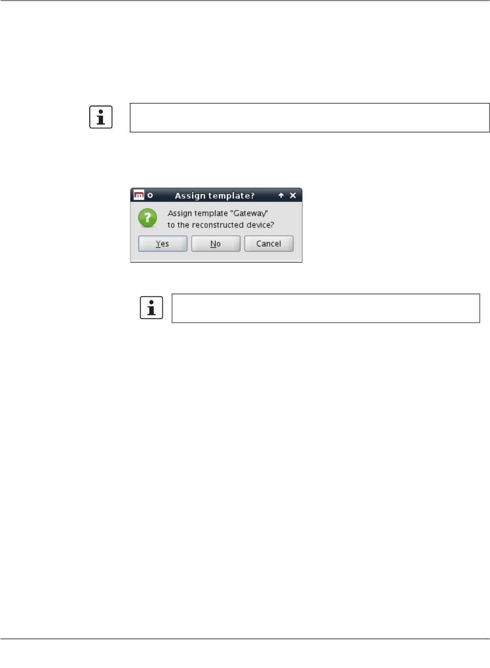
Configuration history
111024_en_01 PHOENIX CONTACT 125
8.4 Reconstructing a device from a historic configura-
tion
When a single history entry is activated in the configuration history dialog by checking the
checkboxes in both the A and the B column, the Reconstruct Device button is enabled.
Clicking on this button creates a new device in which all variables are set according to the
historic configuration and opens the Device properties dialog for the reconstructed device.
Template assignment If the device was assigned to a template when the history entry was created, and if that tem-
plate still exists, and if the firmware version the device had when the history entry was cre-
ated is equal to or newer than the current firmware version of the template, the template can
be assigned to the reconstructed device:
If the template is assigned to the device, variables in the device are set to Inherited if their
value (in the historic configuration) matches the value in the template (in its current state).
Once created, the new device is no longer linked to the device from which it has been re-
constructed. It is an independent device with an independent device history.
If the template uses the No override or May append permission, it may not be
possible to reproduce the historic configuration exactly.

FL MGUARD DM UNLIMITED 1.15.x
126
PHOENIX CONTACT 111024_en_01
8.5 Report of changes
The report of changes allows it to obtain an overview how multiple devices have changed
between two points in time. Select one or more devices in the device overview table and
activate the Generate Report of Changes to Device Configuration option in the context
menu. This opens the history reporting dialog.
Figure 8-2 The dialog to generate a report of changes to device configurations
Selection criteria The two historic configurations to compare are selected by applying two selection criteria,
one to select the older revision and one to select the newer revision, to each selected device
individually. The following criteria can be chosen:
Oldest
The oldest device configuration.
Newest
The newest device configuration.
Newest Before
The newest device configuration prior to a date and time. The date and time is specified as
an ISO date (YYYY-MM-DD where YYYY is the year, MM is the month of the year between
01 and 12, and DD is the day of the month between 01 and 31) optionally followed by an ISO
time (hh:mm:ss where hh is the hour according to the 24-hour timekeeping system, mm is
the minute and ss is the second). For example, a quarter past 4 p.m. and 20 seconds on
December 22nd, 2010 would be written as 2010-12-22 16:15:20.
Alternatively, click on the icon to select the date from a calender.

Configuration history
111024_en_01 PHOENIX CONTACT 127
Device configuration must have been uploaded or exported
The criterion can be combined with the others. If the checkbox is checked, only history en-
tries pertaining to configurations which have been uploaded to an mGuard or exported for
pull configuration are considered.
Generating the report The report consists of an HTML file which can be viewed with any web browser. The name
of the file to which to write the report is specified in the Report field. If the Open finished Re-
port in Browser checkbox is checked, mdm automatically opens a web browser and loads
the report.

FL MGUARD DM UNLIMITED 1.15.x
128
PHOENIX CONTACT 111024_en_01
Creating and managing certificates
111024_en_01 PHOENIX CONTACT 129
9 Creating and managing certificates
It is assumed that the reader has an extensive knowledge of certificates, certificate creating
and public key encryption.
This chapter explains the usage of OpenSSL to create certificates.
It is important to note that mdm requires two different types of certificates and keys:
– Certificates and keys used to secure the communication between the mdm compo-
nents
– Certificates and keys used for the PKI
How to create certificates and keys to be used for the SSL communication is explained in
Chapter 9.1. The certificates and keys used in a PKI are described in Chapter 9.2.
Keystores Certificates and keys are stored in databases called keystores. A keystore is a file, contain-
ing the certificates and keys in encrypted form. To access the information in a keystore a
passphrase is required. Keystores can have different formats, common formats are e.g.
PKCS#12 or the proprietary Java KeyStore format (JKS). The encryption algorithm can usu-
ally be selected when creating the keystore. AES256 is recommended.
The
OpenSSL
configura-
tion file
OpenSSL uses default values specified in the configuration file openssl.cnf (the directory
where this file is located depends on your distribution, e.g. check in the directory /usr/ssl or
/usr/lib/ssl).
If you omit mandatory arguments of a command, OpenSSL uses the default settings defined
in the configuration file. If possible, all mandatory arguments for the example commands
below are explicitly stated, i.e. if you use the commands as described below the important
information is taken from the command line and not from the configuration file. If the config-
uration file is required for the respective command it is explicitly mentioned in the text.
For further information about the syntax and content of the configuration files, please refer
to OpenSSL's documentation, particularly to the manual pages genrsa(1ssl), req(1ssl),
ca(1ssl) and openssl(1ssl).
9.1 Certificates and keys for SSL
To set up a secure connection between entities (e.g. ET1, ET2) usually the following com-
ponents are required:
– a private key for each entity participating in the communication:
– ET1
key
– ET2
key
Create certificates only if you are sure to master the certificate creation.
Please note that the process described in this section to create certificates is just one ex-
ample of the usage of OpenSSL. There are also alternative ways to create your certifi-
cates. If you are not familiar with OpenSSL you should exactly follow the instructions
below.
The use of OpenSSL 1.1.1k or later is recommended, due to several important security
fixes.

FL MGUARD DM UNLIMITED 1.15.x
130
PHOENIX CONTACT 111024_en_01
The term private key already implies that it is important to keep these keys private and
store them at a location only accessible to the administrator.
– and the corresponding certificates:
– ET1
cert
– ET2
cert
The certificates contain among other information
– the public key of the entity
– information about the entity, e.g. the name and/or the IP address
– further information about the certificate, e.g. the intended usage
The certificate is either digitally signed with the private key of the respective entity (self-
signed) or with a CA key.
The certificates are public and can be distributed to anyone participating in the commu-
nication.
ET1 will use the public key contained in ET2
cert
to encrypt the data sent to ET2. This assures
that only ET2 is able to decrypt the data. If ET2
cert
is self-signed it is assured that public key
contained in ET2
cert
corresponds to ET2
key
. If ET2
cert
is signed by a CA it is assured that
the public key contained in ET2
cert
really belongs to ET2 (authentication).
Create the private key ET
key
has to be created first using the following command:
openssl genrsa -aes256 -passout pass:yourSSLPW -out privkey.pem
2048
Explanation of the arguments
:
The command above generates one output file:
privkey.pem
This file contains ET
key
in PEM format. The key is encrypted with the AES256-algorithm. To
access the key you have to know the passphrase specified above (in the example:
yourSSLPW). Please use your own, secure password to encrypt the private key.
Argument Explanation
genrsa genrsa instructs OpenSSL to generate an
RSA key.
-aes256 Use AES256 to encrypt the key.
-passout pass:
password
The password used to encrypt the private key
(in the example: yourSSLPW). yourSSLPW is
just an example and should be replaced by a
secure password.
-out
filename
Name of the file containing ET
key
(in the ex-
ample: privkey.pem).
2048 The length of the key.
Sometimes it is necessary to create an unencrypted key. In this case just omit the -aes256
and the -passout option in the command above.
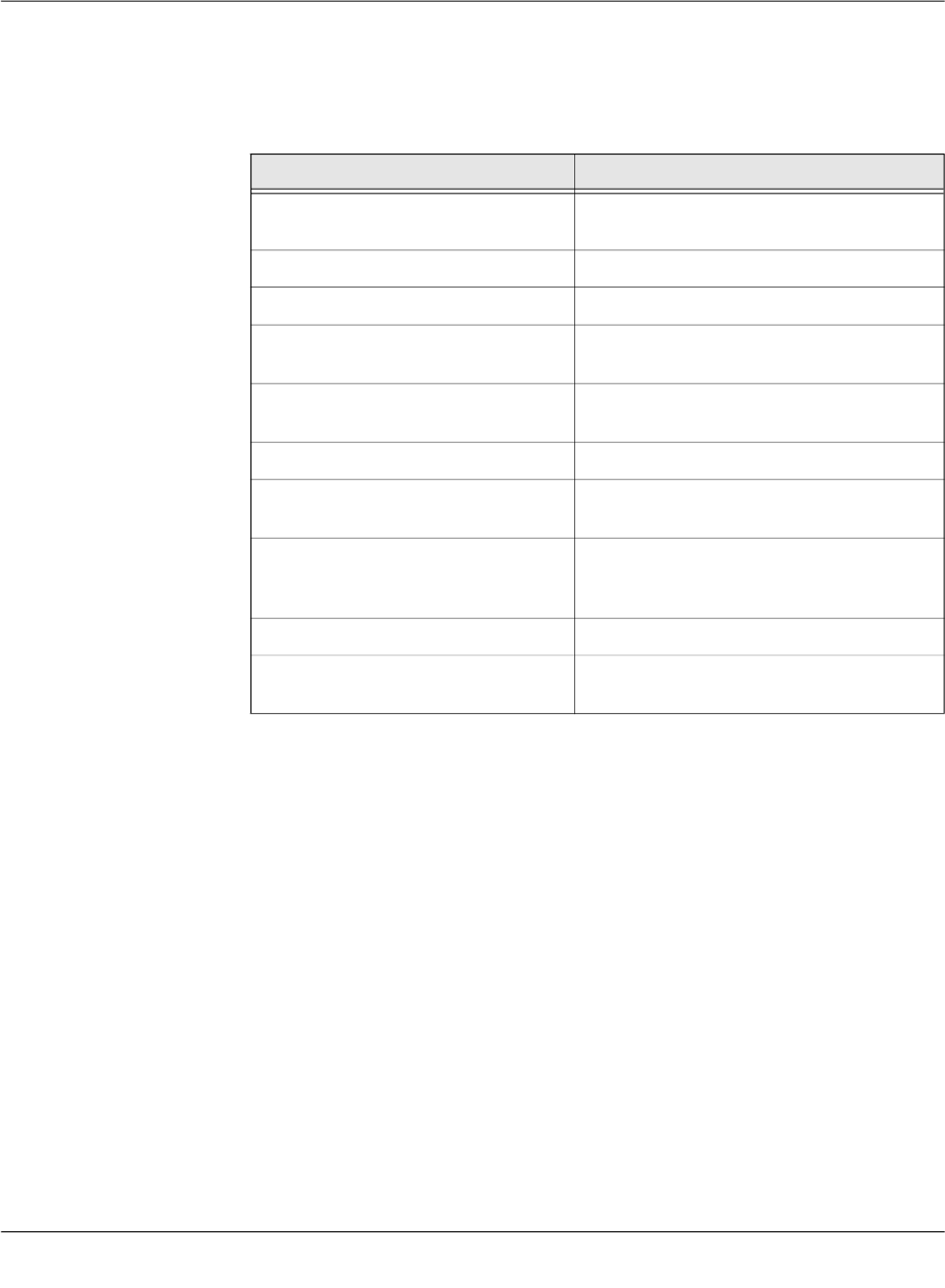
Creating and managing certificates
111024_en_01 PHOENIX CONTACT 131
Create the certificate The certificate is created with the following command:
openssl req -batch -new -x509 -key privkey.pem -keyform PEM
-passin pass:yourSSLPW -sha256 -outform PEM -out serverCert.pem
Explanation of the arguments
:
The command above generates one output file:
serverCert.pem
This file contains the self-signed certificate ET
cert
.
Create a keystore The keys and certificates have to be included in keystores. The mdm VA contains the (pro-
prietary) java tool ImportKey in the /etc/mdm/mdm-ca/demoCA directory which can be used
to create and manage keystores. Please copy the file ImportKey.class to your working di-
rectory.
First ET
key
has to be converted to PKCS#8 format and both ET
key
and ET
cert
have to be in-
cluded in a keystore. In the example, Java KeyStore format (JKS) is used. This can be ac-
complished with the tool ImportKey. ImportKey does accept the (unencrypted) key on stan-
dard input only, therefore the output of the pkcs8 command has to be piped as follows:
openssl pkcs8 -topk8 -in privkey.pem -passin pass:yourSSLPW
-inform PEM -nocrypt -outform DER |java -cp . ImportKey
-alias yourAlias -storetype JKS -keystore serverKeystore.jks
-storepass pass:yourSSLPW -keypass pass:yourSSLPW
-chain serverCert.pem
Argument Explanation
req req instructs OpenSSL to generate a certifi-
cate request (default) or a certificate.
-batch Non interactive mode.
-new Create a new request or a new certificate.
-x509 Create a self signed certificate instead of a
certificate request.
-
key
filename
The corresponding private key (in the exam-
ple: privkey.pem).
-keyform PEM The private key is in PEM format.
-passin pass
:password
Password required to decrypt the private key
(in the example: yourSSLPW).
-sha256 Use the SHA256 algorithm to create the mes-
sage digest for the signature (recom-
mended).
-outform PEM The format of the output file is PEM.
-
out
filename
The name of the output file, i.e. the certificate
(in the example serverCert.pem).
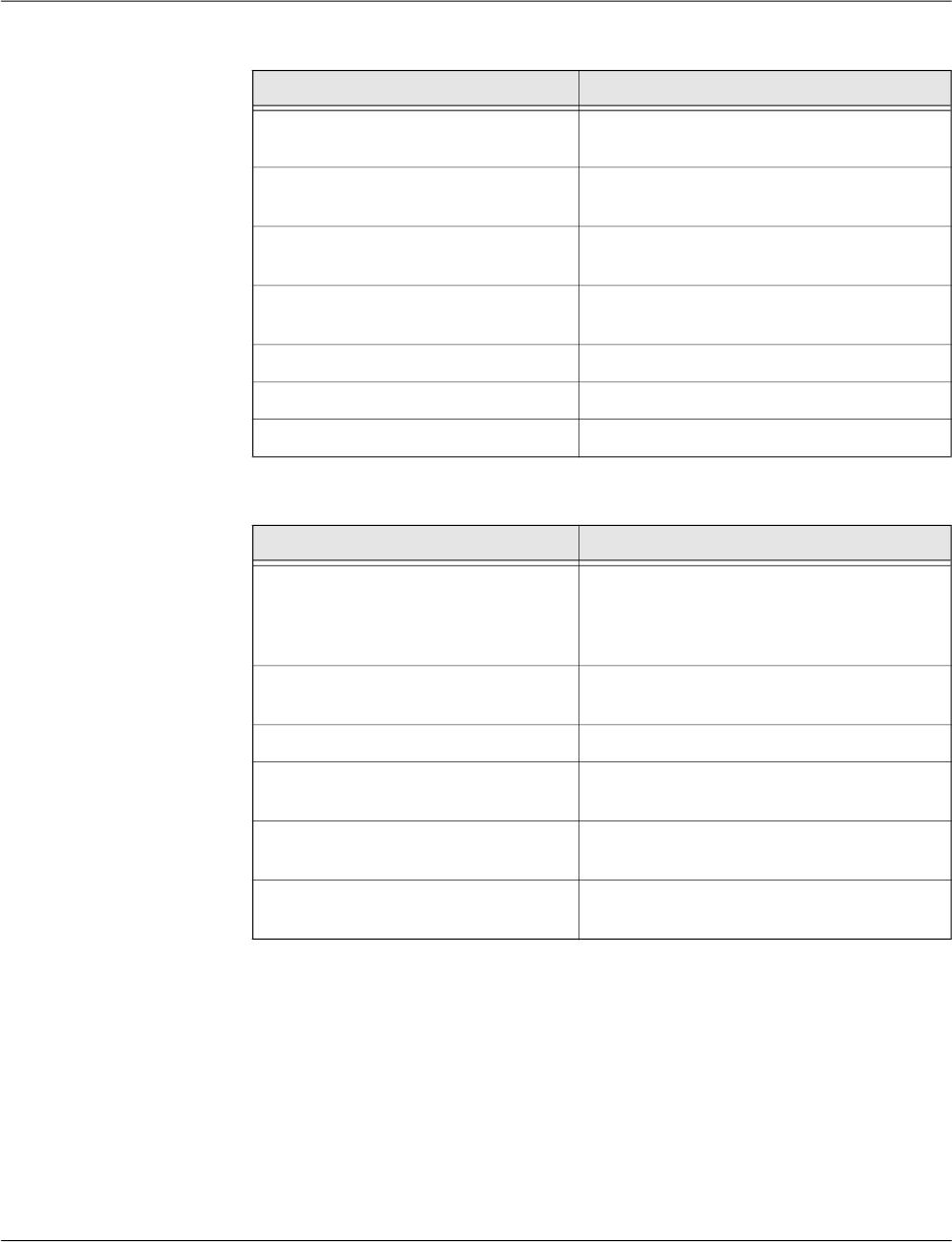
FL MGUARD DM UNLIMITED 1.15.x
132
PHOENIX CONTACT 111024_en_01
Explanation of the
openssl
arguments:
Explanation of the
ImportKey
arguments:
The command above generates one output file:
serverKeyStore.jks
This is the keystore containing the certificate and the private key.
Import a certificate After creating the keystore it is sometimes necessary to import additional certificates into
the keystore. This can be accomplished by using the following command:
java -cp . ImportKey -alias yourAlias -storetype JKS
-file additionalCertificate.pem -storepass pass:yourSSLPW
-keystore serverKeystore.jks
Argument Explanation
pkcs8 The pkcs8 command is used to process pri-
vate keys in PKCS#8 format.
-topk8 Use a traditional format private key as input
and write a key in PKCS#8 format key.
-
in
filename
The name and the location of the input file (in
the example: privkey.pem).
-passin pass:
password
Password required to decrypt the input (in the
example: yourSSLPW).
-inform PEM The input format of the key is PEM.
-nocrypt The output (the key) is not encrypted.
-outform DER The ouput format is DER.
Argument Explanation
-alias
name
A keystore can contain multiple entries. The
alias identifies the entry and therefore has to
be unique in the keystore. Aliases are case-
insensitive.
-keystore
filename
The file containing the keystore (in the exam-
ple: serverKeyStore.jks).
-storetype JKS Use JKS as format for the keystore.
-storepass pass:
password
Password required to decrypt the contents of
the keystore (in the example: yourSSLPW).
-keypass pass:
password
Additional password required to decrypt the
private key in the keystore.
-chain
filename
The certificate (in the example server-
Cert.pem).

Creating and managing certificates
111024_en_01 PHOENIX CONTACT 133
Explanation of the
ImportKey
arguments:
Argument Explanation
-alias
name
A keystore can contain multiple entries. The
alias identifies the entry and therefore has to
be unique in the keystore. Aliases are case-
insensitive.
-keystore
filename
The file containing the keystore (in the exam-
ple: serverKeyStore.jks).
-storetype JKS The format for the keystore.
-storepass pass:
password
Password required to decrypt the contents of
the keystore (in the example: yourSSLPW).
-file
filename
The certificate to be imported (in the example
additionalCertificate.pem).

FL MGUARD DM UNLIMITED 1.15.x
134
PHOENIX CONTACT 111024_en_01
9.2 Certificates and keys for a PKI
When rolling out a Private Key Infrastructure (PKI), which is basically your intent when using
the mdm CA, there are more requirements to be taken into account than mentioned in the
previous chapter. This chapter first describes some of the PKI basics and then the usage of
OpenSSL to roll out a PKI.
PKI basics Among others the main reasons for using a PKI are:
– Authentication
When communicating using data networks it is in most cases not possible to “see” the
entity on the remote side (exception: video telephony), i.e. one cannot be sure that the
entity on the remote side is the one it claims to be. The usage of a PKI assures the au-
thenticity of the entities communicating with each other.
– Data confidentiality
This is the reason VPNs are used to exchange data: The data packets are sent “in the
public” (Internet), but unauthorized entities are prevented from accessing the informa-
tion contained in the packets.
– Data integrity
The assurance that the information received is identical to the information sent by the
other entity. This prevents information to be altered by an entity “in the middle” which is
not authorized to participate in the communication.
It is beyond the scope of this document to describe all components and their interactions
involved in a complete PKI, therefore only the most important are mentioned here:
– Certificates and private keys
Certificates are the means in a PKI to assure authentication. The identity of the certifi-
cate owner is approved by a CA by signing the certificate request of the respective
owner. The public and private keys are used to encrypt/decrypt data and therefore as-
sure data confidentiality.
– Certification Authority (CA)
A Certification Authority is a component in a PKI which assures authenticity of the par-
ticipating entities by signing certificate requests (i.e. issuing certificates). Usually there
are multiple CAs in a PKI organized in a hierarchical structure with one root CA at the
top.
– CRL Distribution Points (CDP)
See the following section Certificate extensions.
– Entities communicating with each other
The entities using a PKI use certificates to authenticate themselves and use the pub-
lic/private key pairs to encrypt/decrypt the exchanged data. The entities request certif-
icates from the CA. Usually a Registration Authority (RA) is also part of a PKI. The RA
is responsible for the initial registration of entities that would like to use the PKI. An RA
is not required in the mdm usage scenario.
Contents of a certificate As mentioned in the previous chapter a certificate contains the following information:
– the public key of the entity
– information about the entity, e.g. the name and/or the IP address
Please note that the certificates described in this section are not used for SSL.
Please note that the certificates and keys described in this section are not stored in the
SSL-keystore of the mdm CA, but in the CA-keystore.

Creating and managing certificates
111024_en_01 PHOENIX CONTACT 135
– further information, e.g. about the certificate and the infrastructure
The following sections explain the contents in more detail.
The Subject Distinguished Name
The Subject Distinguished Name is a unique identifier of the certificate and its owner. It is
composed of several components:
Certificate extensions
Information about the certificate or the infrastructure is contained in the so called certificate
extensions. Basically anyone can define its own extensions, but the standard extensions
(X.509version3) are defined in RFC 3280 Internet X.509 Public Key Infrastructure - Certifi-
cate and CRL Profile. Here is a short description of the extensions that are important for the
mdm CA:
– Critical Bit
The Critical Bit is not an extension but used to force the usage of extensions in the cer-
tificate. The Critical Bit can be set for any extensions in the certificate. Applications ver-
ifying a certificate must be able to interpret an extension with the Critical Bit. If the ap-
plication is not able to interpret the extension, the certificate must be rejected.
– Basic Constraints
The Basic Constraints extension is used to indicate whether the certificate is a CA cer-
tificate or not. Basic Constraints consists of 2 fields:
Abbreviation Name Explanation
CN Common Name Identifies the person or object owning
the certificate. For example: CN=server1
E E-mail Address Identifies the e-mail address of the
owner.
OU Organizational Unit Identifies a unit within the organization.
For example: OU=Research&Develop-
ment
O Organization Identifies the organization. For example:
O=Innominate
L Locality Identifies the place where the entity re-
sides. The locality can e.g. be a city:
L=Berlin
ST State Identifies the state. For example:
ST=Berlin
C Country Two letter code identifying the country.
For example: C=DE (for Germany)
Depending on your policy, not all of the components are mandatory, but if the extension
Subject Alternative Name is not included in the certificate, at least one component that
can be used as identifier has to be included, typically this is the Common Name (CN).
Please note that currently the mdm CA cannot handle certificates with Subject Alternative
Name extensions.

FL MGUARD DM UNLIMITED 1.15.x
136
PHOENIX CONTACT 111024_en_01
– cA field of type BOOLEAN and
– pathLenConstraint field (optional) of type INTEGER
For CA certificates the cA field must be set to true. pathLenConstraint is only used if the
cA field is set to true and specifies the number of CA levels allowed below this certifi-
cate. Basic Constraints should be always marked as critical.
Please refer to Chapter 9.2.3 for requirements regarding the Basic Constraints exten-
sion.
– Key Usage
Key Usage controls the intended use of the certificate’s corresponding keys. A key can
be e.g. used to sign Certificate Revocation Lists (CRL), encrypt data or to sign certifi-
cates.
Please refer to Chapter 9.2.3 for requirements regarding the Key Usage extension.
– Subject Alternative Name
The extension Subject Alternative Name can be used to add more identifiers to the cer-
tificate. Subject Alternative Name can contain e.g. e-mail addresses, domain names
etc. It can be used as substitute for the Subject as well, which must be empty in this
case. Please note that the mdm CA is currently not able to handle Subject Alternative
Name extensions.
– CRL Distribution Points (CDP)
Certificates can be revoked, e.g. if a private key was compromised or if it is no longer
valid. Usually an application has to check whether a certificate is still valid, by checking
the validity period and/or by retrieving revocation information from a CRL distribution
point (CDP). To retrieve the information either Certificate Revocation Lists (CRL) can
be used or a dedicated protocol like OCSP. However, the certificate should contain the
information, which CDP should be contacted.
– Authority Information Access
Authority Information Access is not an X.509 standard extension, but an extension de-
fined by the PKIX working group (http://www.ietf.org/html.charters/pkix-charter.html).
Authority Information Access contains information about the issuing CA, e.g. policies,
further root certificates or where to retrieve the higher certificates in the chain, if the
complete chain is not contained in the certificate.
Depending on the settings of these extensions the receiver (not the owner) of a certifi-
cate accepts or denies the communication with the peer, thus preventing any misuse of
certificates and creating a higher level of security.
9.2.1 Create the CA certificates
Depending on your existing infrastructure the mdm CA needs the following certificates:
– A self-signed root certificate (CA
rootCert
) and the matching private key (CA
rootKey
).
If you have another upstream (root) CA in place, there is no need to generate the root
certificate and the matching private key.
The (self-signed) root certificate is distributed to all entities participating in the commu-
nication. It is used by the entities to verify the authenticity of the communication peer
and of any intermediate CAs in the certificate chain. The private key CA
rootKey
is used
to sign the self-signed root certificate.
– A CA certificate (CA
cert
) and the matching private key (CA
key
). This is the certificate
used by the CA to authenticate itself to other entities. This certificate has to be signed
with the root private key, i.e. either with CA
rootKey
or with the key of your existing root
CA. The private key CA
key
is used to sign the certificate request sent by the mdm serv-
er, i.e. it is used to issue certificates for the mGuards.
– A template certificate (CA
templCert
) which is used by the CA as template when issuing
end entity (mGuard) certificates.

Creating and managing certificates
111024_en_01 PHOENIX CONTACT 137
Figure 9-1 shows the certificate hierarchy:
Figure 9-1 mdm CA certificate hierarchy
In the following it is assumed that there is no other root CA in place and that the mdm CA is
used as root CA.
Create the root certificate The following OpenSSL commands require input from the OpenSSL configuration file
openssl.cnf (the directory where this file is located depends on your distribution, e.g. check
in the directory /usr/ssl or /usr/lib/ssl). Instead of changing the standard configuration file of
your OpenSSL installation, it is recommend to use the example configuration files provided
in the mdm VA in the directory /etc/mdm/mdm-ca and adapt those files to your needs. You
can instruct OpenSSL to use the provided configuration files instead of the standard config-
uration file.
Adapt the OpenSSL configuration file
Please copy the file rootCert.conf provided in the directory /etc/mdm/mdm-ca/demoCA in
the mdm VA to your working directory. Adapt the [ root_dn ] section of the file, which
contains the Subject Distinguished Name of your root CA certificate:
[ root_dn ]
C= DE
O= Innominate Security Technologies AG
OU= Research & Development
CN= Test Root CA
Please note also the [ root_ext ] section of the configuration file, which is important for
the proper generation of the root certificate (please refer to Section Certificate extensions
for an explanation):
[ root_ext ]
keyUsage= cRLSign, keyCertSign
basicConstraints= critical, CA:true, pathlen:1
Important: Please keep the private key(s) at a secure location. In particular this is re-
quired for the root CA’s private key.
It is recommended to create a working directory, e.g. called security in the mdm installa-
tion directory, where all the certificates and keys created during the following process are
located.
CA
rootCert
self-signed
CA
cert
signed with CA
rootKey
CA
templCert
mGuard1
Cert
...
signed with CA
key

FL MGUARD DM UNLIMITED 1.15.x
138
PHOENIX CONTACT 111024_en_01
Generate the private key
CA
rootKey
has to be created first using the following command:
openssl genrsa -aes256 -passout pass:rootPW
-out rootKey.pem 2048
Explanation of the arguments:
The command above generates one output file:
rootKey.pem
This file contains CA
rootKey
in PEM format. The key is encrypted with the AES256-algorithm.
To access the key you have to know the passphrase specified above (in the example:
rootPW). Please use your own, secure password to encrypt the private key.
Generate the root certificate
The OpenSSL command used to generate CA
rootCert
is:
openssl req -batch -new -config rootCert.conf -x509
-key rootKey.pem -keyform PEM -passin pass:rootPW -sha256 -days
5479 -outform PEM -out rootCert.pem
Explanation of the arguments:
Argument Explanation
genrsa genrsa instructs OpenSSL to generate an
RSA key.
-aes256 Use AES256 to encrypt the key.
-passout pass:
password
The password used to encrypt the private key
(in the example: rootPW). rootPW is just an
example and should be replaced by a secure
password.
-out
filename
Name of the file containing CA
rootKey
(in the
example: rootKey.pem).
2048 The length of the key.
Argument Explanation
req req instructs OpenSSL to generate a certifi-
cate request (default) or a certificate.
-batch Non interactive mode.
-new Create a new request or a new certificate.
-config
filename
The name and the location of the openssl
configuration file (in the example: root-
Cert.conf).
-x509 Create a self signed certificate instead of a
certificate request.

Creating and managing certificates
111024_en_01 PHOENIX CONTACT 139
The command above generates one output file:
rootCert.pem
This file contains the self-signed root certificate CA
rootCert
.
Create the CA certificate The intermediate CA certificate CA
cert
is not self-signed but will be issued (signed) by the
root CA. Therefore you first have to create a private key and a corresponding certificate re-
quest and then “send” this certificate request to the root CA. The root CA will in return issue
CA
cert
.
First the configuration file has to be adapted to your needs, as described in the previous sec-
tion.
Adapt the OpenSSL configuration file and the environment
Please copy the file caCert.conf contained in the directory /etc/mdm/mdm-ca/demoCA in
the mdm VA to your working directory. Adapt the [ ca_dn ] section of the file, which contains
the Subject Distinguished Name of your root CA certificate:
[ ca_dn ]
C= DE
O= Innominate Security Technologies AG
OU= Research & Development
CN= Test CA
Please adapt also entries crlDistributionPoints and authorityInfoAccess of
the [ ca_ext ] section of the configuration file (please refer to Section Certificate extensions
for an explanation):
[ ca_ext ]
crlDistributionPoints=URI:http://ca.example.com/ca-ca.crl
authorityInfoAccess=OCSP;URI:http://ca.example.com/ocsp/ca-ca
The configuration file contains some parameters, which cannot be entered on the command
line. The entries specify files that have to be present in the file system. Therefore the files
have to be created manually first (the filenames are also used in the configuration file ca-
Cert.conf , therefore please use exactly the file names as stated below):
-key
filename
The corresponding private key (in the exam-
ple: rootKey.pem).
-keyform PEM The private key is in PEM format.
-passin pass:
password
Password required to decrypt the private key
(in the example: rootPW).
-sha256 Use the SHA256 algorithm to create the mes-
sage digest for the signature (recom-
mended).
-days
5479
The period for which the certificate will be
valid.
-outform PEM The format of the output file is PEM.
-out
filename
The name of the output file, i.e. the certificate
(in the example rootCert.pem).
Argument Explanation
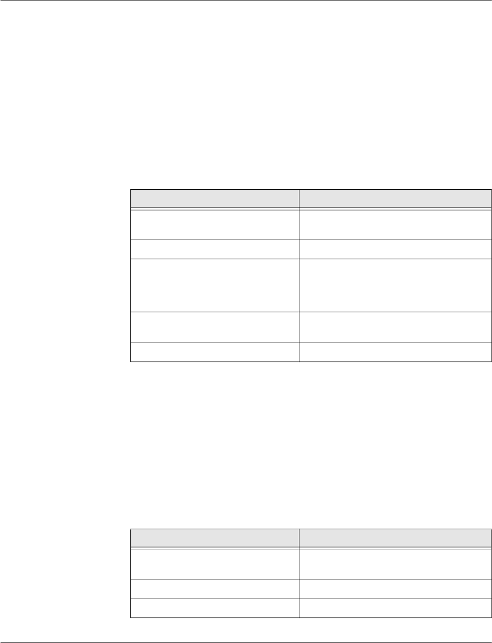
FL MGUARD DM UNLIMITED 1.15.x
140
PHOENIX CONTACT 111024_en_01
– Create a subdirectory archive in your working directory
(Linux: mkdir ./archive)
– Create a file named serial containing a valid serial number for the certificate in the sub-
directory archive
(Linux: echo 1234 > archive/serial)
– Create an empty file to be used as openssl database.
(Linux: touch archive/index.txt
Windows: copy NUL: archive/index.txt)
Generate a private key
The private key CA
key
has to be created first using the following command:
openssl genrsa -aes256 -passout pass:caPW -out caKey.pem 2048
Explanation of the arguments:
This command generates one output file:
caKey.pem
This file contains CA
key
in PEM format. The key is encrypted with the AES256-algorithm. To
access the key you have to know the passphrase specified above (in the example: caPW).
Please use your own, secure password to encrypt the private key.
Generate a certificate request
To create a certificate request enter the following command:
openssl req -batch -new -config caCert.conf
-key caKey.pem -keyform PEM -passin pass:caPW -sha256
-out caCertReq.pem -outform PEM
Explanation of the arguments:
Argument Explanation
genrsa genrsa instructs OpenSSL to generate an
RSA key.
-aes256 Use AES256 to encrypt the key.
-passout pass:
password
The password used to encrypt the private key
(in the example: caPW). caPW is just an ex-
ample and should be replaced by a secure
password.
-out
filename
Name of the file containing the private key (in
the example: caKey.pem).
2048 The length of the key.
Argument Explanation
req req instructs OpenSSL to generate a certifi-
cate request (default) or a certificate.
-batch Non interactive mode.
-new Create a new request.
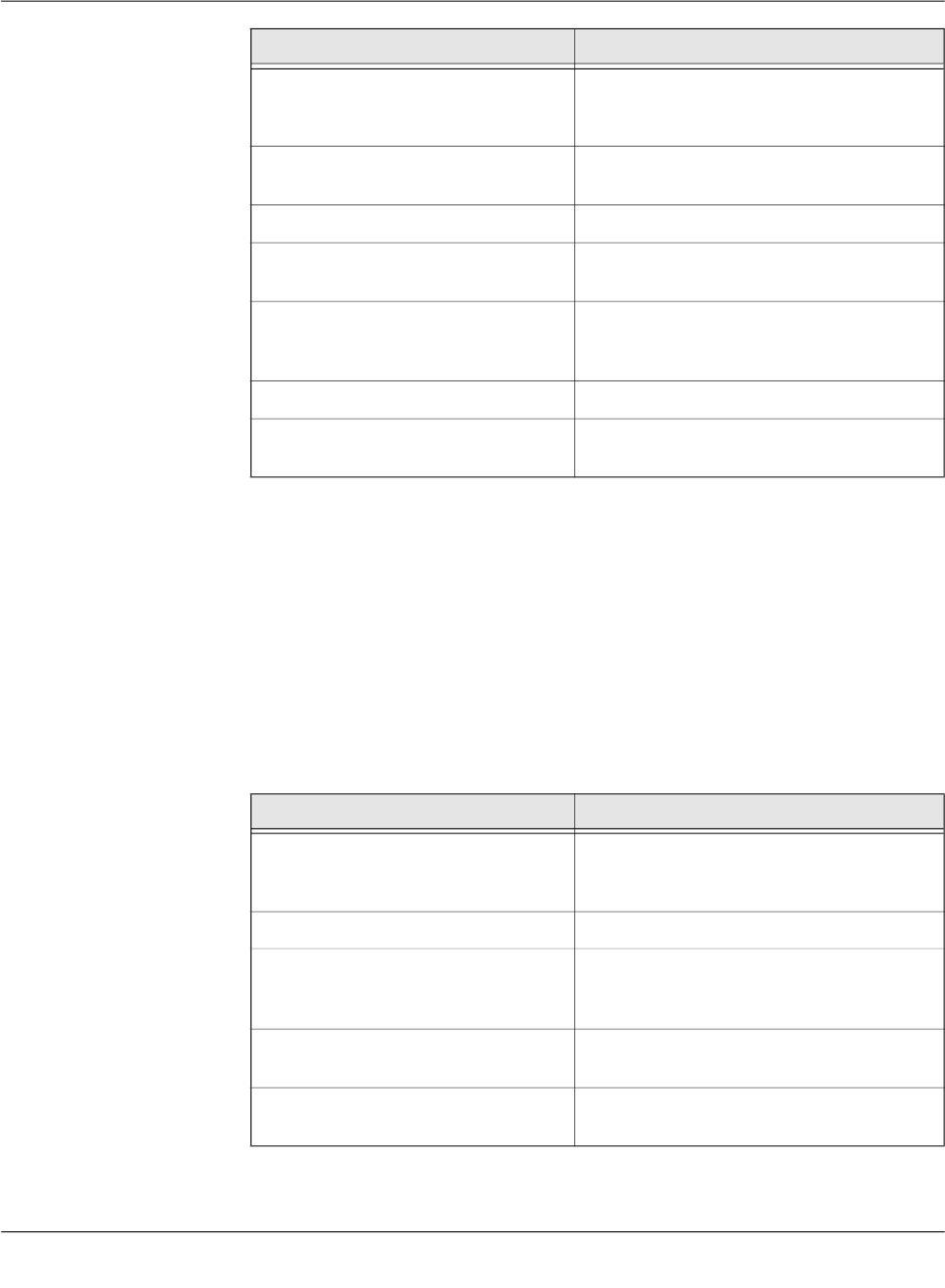
Creating and managing certificates
111024_en_01 PHOENIX CONTACT 141
The command above generates one output file:
caCertReq.pem
This file contains the certificate request.
Request the CA certificate
The request has to be sent to the root CA. Since the mdm CA is the root CA in the example
you can issue the certificate with the following command:
openssl ca -batch -config caCert.conf -days 3653
-in caCertReq.pem -cert rootCert.pem -keyfile rootKey.pem
-passin pass:rootPW -md sha256 -notext -out caCert.pem
-outdir .
Explanation of the arguments:
-config
filename
The name and the location of the openssl
configuration file (in the example: ca-
Cert.conf).
-key
filename
The corresponding private key (in the exam-
ple: caKey.pem).
-keyform PEM The private key is in PEM format.
-passin pass:
password
Password required to decrypt the private key
(in the example: caPW).
-sha256 Use the SHA256 algorithm to create the mes-
sage digest for the signature (recom-
mended).
-outform PEM The format of the output file is PEM.
-out
filename
The name of the output file, i.e. the certificate
(in the example caCertReq.pem).
Argument Explanation
ca The ca command is a minimal CA application.
It can be used to sign certificate requests and
generate CRLs.
-batch Non interactive mode.
-config
filename
The name and the location of the openssl
configuration file (in the example: ca-
Cert.conf).
-days
3653
The period for which the certificate will be
valid.
-in
filename
The name of the file containing the certificate
request (in the example: caCertReq.pem).
Argument Explanation

FL MGUARD DM UNLIMITED 1.15.x
142
PHOENIX CONTACT 111024_en_01
The command above generates one output file:
caCert.pem
This file contains CA
cert
.
Create a certificate tem-
plate
The purpose of the CA is to issue certificates. To do so the CA needs instructions how the
certificates to be issued should look like, e.g. which extensions should be included. This can
be accomplished by providing the CA with a certificate template (CA
templCert
). CA
templCert
is
a certificate issued by the CA. To issue a certificate you first have to adapt an OpenSSL con-
figuration file again.
Adapt the OpenSSL configuration file
Please copy the file templateCert.conf contained in the directory /etc/mdm/mdm-
ca/demoCA in the mdm VA to your working directory. Adapt the entries crlDistribu-
tionPoints and authorityInfoAccess of the [ template_ext ] section of the configu-
ration file (please refer to Section Certificate extensions for an explanation):
[ template_ext ]
crlDistributionPoints=URI:http://ca.example.com/ca-ee.crl
authorityInfoAccess=OCSP;URI:http://ca.example.com/ocsp/ca-ee
Generate a private key
The private key has to be created first using the following command:
-cert
filename
The name of the file containing the root certif-
icate (in the example: rootCert.pem).
-keyfile
filename
The name of the file containing the key used
to sign the certificate request (in the example:
rootKey.pem).
-passin pass:
password
Password required to decrypt the private key
(in the example: rootPW).
-md sha256 Use the SHA256 algorithm to create the mes-
sage digest for the signature (recom-
mended).
-notext openssl has an option to include human read-
able, explanatory text in the certificate. But
this would create problems later in the pro-
cess when creating the keystores, therefore
do not include any text in the certificate.
-outdir
directoryName
The output directory (in the example the cur-
rent working directory “.”).
The file caCertReq.pem is not required any more and should be deleted.
Argument Explanation
Please note that the configuration file templateCert.conf expects files to be existent that
have to be manually created. (see previous section Create the CA certificate, subsection
Adapt the OpenSSL configuration file and the environment).
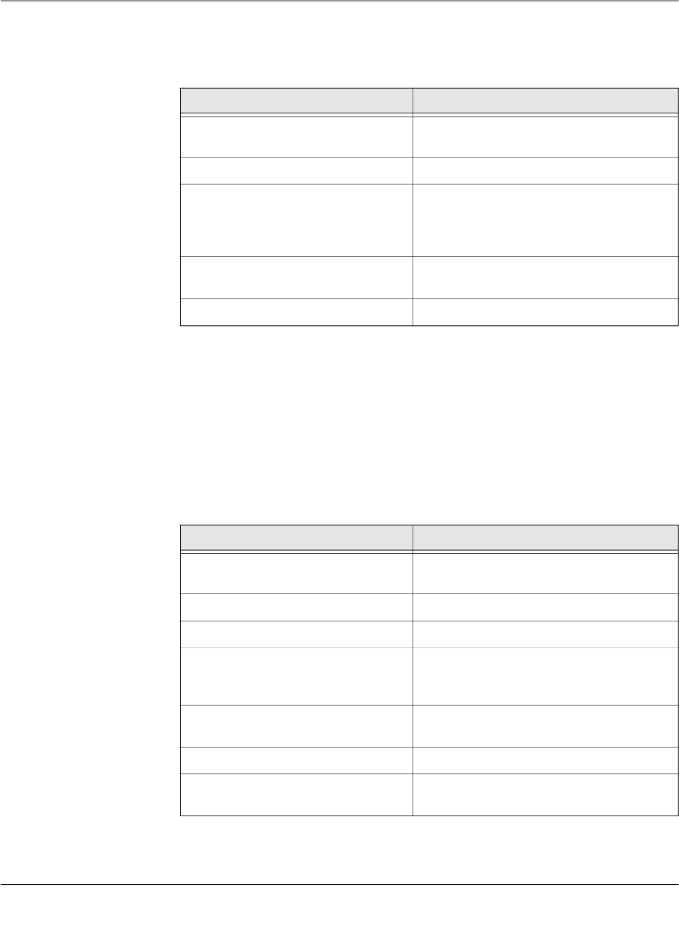
Creating and managing certificates
111024_en_01 PHOENIX CONTACT 143
openssl genrsa -aes256 -passout pass:caPW -out templateKey.pem
2048
Explanation of the arguments:
This command generates one output file:
templateKey.pem
This file contains the encrypted private key.
Generate a certificate request
To create a certificate request enter the following command:
openssl req -new -batch -config templateCert.conf
-key templateKey.pem -keyform PEM -passin pass:caPW
-sha256 -outform PEM -out templateCertReq.pem
Explanation of the arguments:
Argument Explanation
genrsa genrsa instructs OpenSSL to generate an
RSA key.
-aes256 Use AES256 to encrypt the key.
-passout pass:
password
The password used to encrypt the private key
(in the example: caPW). caPW is just an ex-
ample and should be replaced by a secure
password.
-out
filename
Name of the file containing the private key (in
the example: templateKey.pem).
2048 The length of the key.
Argument Explanation
req req instructs OpenSSL to generate a certifi-
cate request (default) or a certificate.
-batch Non interactive mode.
-new Create a new request or a new certificate.
-config
filename
The name and the location of the openssl
configuration file (in the example: template-
Cert.conf).
-key
filename
The corresponding private key (in the exam-
ple: templateKey.pem).
-keyform PEM The private key is in PEM format.
-passin pass:
password
Password required to decrypt the private key
(in the example: caPW).

FL MGUARD DM UNLIMITED 1.15.x
144
PHOENIX CONTACT 111024_en_01
The command above generates one output file:
templateCertReq.pem
This file contains the certificate request.
Request the template certificate
The request has to be sent to the (intermediate) CA. You can sign the certificate request (is-
sue the certificate) with the following command:
openssl ca -batch -config templateCert.conf -days 1826
-md sha256 -in templateCertReq.pem -keyfile caKey.pem
-cert caCert.pem -passin pass:caPW -notext
-out templateCert.pem -outdir .
Explanation of the arguments:
-sha256 Use the SHA256 algorithm to create the mes-
sage digest for the signature (recom-
mended).
-outform PEM The format of the output file is PEM.
-out
filename
The name of the output file, i.e. the certificate
(in the example templateCertReq.pem).
Argument Explanation
ca The ca command is a minimal CA application.
It can be used to sign certificate requests and
generate CRLs.
-batch Non interactive mode.
-config
filename
The name and the location of the openssl
configuration file (in the example: template-
Cert.conf).
-days
1826
The period for which the certificate will be
valid.
-in
filename
The name of the file containing the certificate
request (in the example: templateCer-
tReq.pem).
-cert
filename
The name of the file containing the root certif-
icate (in the example: caCert.pem).
-keyfile
filename
The name of the file containing the key used
to sign the certificate request (in the example:
caKey.pem).
-passin pass:
password
Password required to decrypt the private key
(in the example: caPW).
Argument Explanation

Creating and managing certificates
111024_en_01 PHOENIX CONTACT 145
The command above generates one output file:
templateCert.pem
This file contains CA
templCert
. The file should be copied to its final destination, the location
must be configured in ca-preferences.xml in the node certificateFactory » certTemplate.
9.2.2 Create the keystores
After following the steps described in Chapter 9.2.1 you should find the following files in your
working directory:
–
templateCert.pem
This file contains CA
templCert
, signed with CA
key
.
–
caCert.pem
This file contains CA
cert
, signed withCA
rootKey
.
–
caKey.pem
This file contains CA
key
.
–
rootCert.pem
This file contains the self-signed root certificate CA
rootCert
.
–
rootKey.pem
This file contains the encrypted private root key CA
rootKey
.
Some of those files have to be included in keystores. The mdm VA contains the (proprietary)
java tool ImportKey in the directory /etc/mdm/mdm-ca/demoCA which can be used to cre-
ate and manage keystores. Please copy the file ImportKey.class to your working directory.
First the intermediate CA certificate and the root certificate have to be merged into one file
(create a certificate chain):
cat caCert.pem rootCert.pem > caCertWithChain.pem
Then the key caKey.pem has to be converted to PKCS#8 format and both CA
key
and the
certificate chain have to be included in a PKCS#12 keystore. This can be accomplished with
the tool ImportKey. ImportKey does accept the (unencrypted) key on standard input only,
therefore the output of the pkcs8 command has to be piped as follows:
openssl pkcs8 -topk8 -in caKey.pem -passin pass:caPW
-inform PEM -nocrypt -outform DER |
java -cp . ImportKey -alias ca -keystore ca-keystore.jks -
storetype JKS -storepass pass:caPW -keypass pass:caPW
-chain caCertWithChain.pem
-md sha256 Use the SHA256 algorithm to create the mes-
sage digest for the signature (recom-
mended).
-notext openssl has an option to include human read-
able, explanatory text in the certificate. But
this would create problems later in the pro-
cess when creating the keystores, therefore
do not include any text in the certificate.
-outdir
directoryName
The output directory (in the example the cur-
rent working directory “.”).
The files templateCertReq.pem and templateKey.pem are not needed any more and
should be deleted.
Argument Explanation

FL MGUARD DM UNLIMITED 1.15.x
146
PHOENIX CONTACT 111024_en_01
Explanation of the
openssl
arguments:
Explanation of the
ImportKey
arguments:
The command above generates one output file:
ca-keystore.jks
This is the keystore for your CA containing the certificate chain and the private CA key.
Please copy the keystore to its final destination.
– The filename including the absolute or relative path of this keystore has to be con-
figured in the ca-preferences.xml file in the node certificateFactory » keyStore.
– The password to access the keystore (in the example caPW) has to be configured
in the ca-preferences.xml file in the node certificateFactory » keyStorePassword.
– The format of this keystore (Java KeyStore – JKS) has to be configured in the
ca-preferences.xml file in the node certificateFactory » keyStoreType.
Argument Explanation
pkcs8 The pkcs8 command is used to process pri-
vate keys in PKCS#8 format.
-topk8 Use a traditional format private key as input
and write a key in PKCS#8 format key.
-in filename The name and the location of the input file (in
the example: caKey.pem).
-passin pass:password Password required to decrypt the input (in the
example: caPW).
-inform PEM The input format of the key is PEM.
-nocrypt The output (the key) is not encrypted.
-outform DER The output format is DER.
Argument Explanation
-alias name A keystore can contain multiple entries. The
alias identifies the entry and therefore has to
be unique in the keystore. Aliases are case-
insensitive.
-keystore filename The file containing the keystore (in the exam-
ple: ca-keystore.jks).
-storetype JKS Use JKS as format for the keystore.
-storepass pass:password Password required to decrypt the contents of
the keystore (in the example: caPW).
-keypass pass:password Additional password required to decrypt the
private key in the keystore.
-chain filename The certificate chain including the root certifi-
cate.

Creating and managing certificates
111024_en_01 PHOENIX CONTACT 147
– The password to access the private key (in the example caPW) has to be config-
ured in the ca-preferences.xml file in the node certificateFactory » keyPassword.
– The alias (ca) of the key has to be configured in the ca-preferences.xml file in the
node certificateFactory » keyAlias.
9.2.3 Requirements for certificates
For proper function of the VPN certificates also with future versions of the mGuard firmware
and the mdm, the certificates have to satisfy the following requirements:
1. The private key should have a length of at least 1024 bits. Phoenix Contact recom-
mends a key length of 2048 bits for long term security.
2. Any certificate must conform to RFC 3280.
3. Any CA certificate must contain a Basic Constraints extension marked as critical and
with the boolean cA field set to true.
4. Phoenix Contact strongly recommends to include the pathLenConstraint field in any CA
certificate's Basic Constraints extension. It must be set to one less than the number of
descendant CA certificates. So for a typical scenario where a certification chain is made
up of one root CA certificate, a single intermediate CA certificate and an end entity cer-
tificate (VPN certificate in this case), the pathLenConstraint must be one (1) for the root
CA certificate and zero for the intermediate CA certificate.
5. The template VPN certificate must have a Basic Constraints extension marked as crit-
ical with the boolean cA field set to false and without a pathLenConstraint field.
6. Any CA certificate must contain a Key Usage extension marked as critical with the bit
keyCertSign set. It is recommended to have the bit cRLSign set as well.
7. The template VPN certificate does not need to contain any Key Usage extension.
8. Any intermediate CA certificate must contain one or both of the extensions CRL Distri-
bution Points and Authority Information Access, if it is planned to distribute revocation
information online with a future release of the mdm and the mGuard firmware. The ex-
tensions must be marked as non-critical. The former extension is required if it is intend-
ed to use Certificate Revocation Lists (CRLs) in the future. The latter extension is
required if it is intended to use the Online Certificate Status Protocol (OCSP, see
RFC 2560) in the future. Any of the extensions must contain HTTP URLs only.
9. The template VPN certificate should contain one or both of the extensions CRL Distri-
bution Points and Authority Information Access, described above, if it is planned to dis-
tribute revocation information online in the future. Alternatively, the mdm server can be
instructed to include them within the certification request sent to the mdm CA. The latter
is more flexible, because this way the location of the revocation information (CRL) re-
spectively information service (OCSP) can be set for groups of devices or even for in-
dividual devices.
Please note: If the template VPN certificate already includes any of the extension and
the mdm is instructed to include it within the certification request as well, the extension
from the request overrides the one found within the template. The issued certificate will
contain the extension copied from the request.
10. The keystore containing the certificates has to contain the complete certificate chain up
to and including the root certificate.
The file caCertWithChain.pem is not needed any more and should be delet-
ed.

FL MGUARD DM UNLIMITED 1.15.x
148
PHOENIX CONTACT 111024_en_01

Configure mdm server and mdm CA server
111024_en_01 PHOENIX CONTACT 149
10 Configure mdm server and mdm CA server
In order to operate properly, the mdm server requires an XML preferences file as a config-
uration file, which can be specified during server start-up (see “mdm server and mdm client”
on page 15).
A default configuration file (preferences.xml) is contained in the mdm VA in the directory
/etc/mdm/mdm-server.
10.1 mdm server (
preferences.xml
file)
Node
com
Default setting (do not change!)
node
innominate
Default setting (do not change!)
node
innomms
Default setting (do not change!)
node
is
Key
expertMode
If set to true, some unsupported configuration variables which are normally hidden are
made available in the Device and Template properties dialog (default: false). Additionally,
the mGuards are configured such that unsupported configuration variables become visible
in their web interfaces. Please do not change this value!
Key
defaultAdminPassword
The password of the admin user on newly created mGuards (default: mGuard). The default
value corresponds to the mGuard factory default. If mGuard devices are pre-configured be-
fore they are used with mdm, a different default admin password can be set and the data-
base must be updated by the following command:
java -Xmx1024m -jar mdm-server-1.15.x.jar update preferences.xml
Key
defaultRootPassword
The password of the root user on newly created mGuards (default: root). The default value
corresponds to the mGuard factory default. If mGuard devices are pre-configured before
they are used with mdm, a different default root password can be set and the database must
be updated by the following command:
java -Xmx1024m -jar mdm-server-1.15.x.jar update preferences.xml
Node
license
Key
licenseFile
Name and path of the license file.
Node
device
Node
licenseServer
– Key
proto
The protocol to be used to access the license server (default: http). Please do not
change this value.
There are several passwords to be configured in the preferences.xml file. The respective
keys accept the ENV:VARNAME pattern as value to take the password from the environ-
ment variable with name VARNAME. If you decide to use this pattern, please make sure
that the respective environment variables are initialized before starting the server.

FL MGUARD DM UNLIMITED 1.15.x
150
PHOENIX CONTACT 111024_en_01
– Key
address
The address of the license server (default: online.license.innominate.com). Please
do not change this value.
– Key
port
The port to be used to access the license server (default: 80). Please do not
change this value.
– Key
reqPage
The CGI script to be called when requesting licenses (default: cgi-bin/autoreq.cgi).
Please do not change this value.
– Key
refPage
The CGI script to be called when refreshing licenses (default:
cgi-bin/autorefresh.cgi). Please do not change this value.
– Key
reqProfKey
The CGI script to be called when requesting profile keys (default:
cgi-bin/autodevcert.cgi). Please do not change this value.
– Key
reqUsername
The user name needed to request profile keys. Please contact Phoenix Contact
support to obtain a user name.
– Key
reqPassword
The password needed to request profile keys. Please contact Phoenix Contact
support to obtain a user name.
– Key
retries
The number of retries to contact the license server (default: 3). Please do not
change this value.
– Key
timeout
The timeout in seconds when contacting the license server (default: 60). Please do
not change this value.
Node
connection
– Key
useProxy
Here you can configure whether a proxy should be used to contact the license
server (default: false).
– Key
proxyAddress
The address of the proxy to contact the license server (default: 127.0.0.1).
– Key
proxyPort
The port of the proxy to be used to access the license server (default: 3128).
– Key
proxyRequiresAuthentication
Boolean defining whether the proxy requires authentication (default: false).
– Key
proxyAuthenticationUsername
Key
proxyAuthenticationPassword
Key
proxyAuthenticationRealm
The credentials to be used if the proxy requires authentication (default: empty).
Node
service
Key
address
The IP address designating the network interface on which the server is listening for client
connections. If you specify 0.0.0.0, the server is listening on all interfaces (default:
127.0.0.1).
Key
port
The port number on which the server is listening for client connections (default: 7001).
Configure mdm server and mdm CA server
111024_en_01 PHOENIX CONTACT 151
Key
backlog
Number of log entries to be stored (default: 50).
Key
storage
The storage to be used (default: database).
Node
security
Key
keyStore
Name and path of the keystore file.
Key
keyStoreType
Format of the keystore, either JKS (Java KeyStore) or PKCS12 (OpenSSL).
Key
keyStorePassword
Password for the keystore file. The special value ENV:PASSWORD_SSL will cause the
mdm server to read this password upon startup from the environment variable named
PASSWORD_SSL; the name PASSWORD_SSL is just an example and can be
changed if desired.
Key
trustStore
Name and path of the truststore file.
Key
trustStoreType
Format of the truststore, either JKS (Java KeyStore) or PKCS12 (OpenSSL).
Key
trustStorePassword
Password for the truststore file. The special value ENV:PASSWORD_SSL will cause
the mdm server to read this password upon startup from the environment variable
named PASSWORD_SSL; the name PASSWORD_SSL is just an example and can be
changed if desired.
Node
session
Key
maxInactiveInterval
The maximum time interval of inactivity (in seconds) that the server will keep a session
open between client accesses.
A negative or zero time (default) indicates a session should never time out.
Key
maxConcurrentSessions
The maximum number of concurrent sessions (= connected clients). A negative or zero
count (default) indicates that the upper limit of the number of concurrent sessions is de-
fined by the license.
Please note that this timeout will be reset only, if there is an interaction be-
tween client and server. Actions that are local to the client, i.e. scrolling in a
table or changing between the device, template, pool, or VPN group tab will
not reset the inactive timeout.
FL MGUARD DM UNLIMITED 1.15.x
152
PHOENIX CONTACT 111024_en_01
Node
storage
–
Node
database
– Key
host
The IP address (or hostname) mdm should connect to to get access to the
PostgreSQL database (default: 127.0.0.1).
– Key
port
The port that mdm should use to connect to the database (default: 5432).
– Key
name
The name of the database (default: innomms).
– Key
user
The user of the database (default: innomms).
– Key
password
The password to be used to connect to the database (default:
ENV:PASSWORD_DB).The special value ENV:PASSWORD_DB will cause the
mdm server to read this password upon startup from the environment variable
named PASSWORD_DB; the name PASSWORD_DB is just an example and can
be changed if desired.
– Key
ssl
Enable/disable secure connection between the mdm server and the PostgreSQL
server. Please note that enabling this option requires additional installation steps
(default: false).
–
Node
update
– Node
scheduler
Key
tries
Maximum number of attempts for an upload or export of a device
configuration. If this maximum is reached, mdm will stop trying to upload a
configuation to the device (default: 5).
Key
timeout
Maximum number of seconds until an upload of the device configuration is
cancelled. After the timeout is reached, mdm will stop trying to upload a
configuation to the device (default: 600).
Key
rescheduleDelay
Number of seconds between upload attempts (default: 45).
– Node
firmwareUpgradeScheduler
Key
tries
Maximum number of connections mdm should attempt to get feedback from
the device on the result of the firmware upgrade. If this maximum is reached,
mdm will stop trying to contact the device (default: 5).
Key
timeout
Maximum number of seconds until mdm stops to contact a device for the
result of a firmware upgrade. After the timeout is reached, mdm will indicate
that the firmware upgrade failed (default: 3600).
Key
rescheduleDelay
Please make sure that the values for port, name, user and password match
the values you specified during the PostgreSQL installation.

Configure mdm server and mdm CA server
111024_en_01 PHOENIX CONTACT 153
Intervall in seconds between two attempts to obtain the result of a firmware
upgrade from the device (default: 300).
– Node
ssh
Key
connectTimeout
Timeout for the initial SSH connect to a device (default: 60).
Key
socketTimeout
Timeout for the SSH connection TCP/IP socket, e.g. lost connection (default:
120).
Key
deadPeerDetectionTimeout
This timeout will get activated, if a device did not answer a command started
on the device (default: 120).
– Node
pull
Node
export
Key
directory
The export base directory on the server where the configuration files
should be exported to (e.g. for the configuration pull). Please note that
the configuration files are always exported by the server and not the
client, i.e. the client does not have any access to the files. The specified
directory pathname should have the appropriate format of the respective
OS (default: the default temporary directory of your installation, e.g. /tmp
for Linux).
Key
filenames
A comma-separated list of naming schemes for pull configuration
exports.
dbid: A unique ID (automatically assigned) is used as filename and the
files are written to the export base directory.
serial: The serial number is used as filename and the files are written to
the serial/ subdirectory of the export base directory.
mgntid: The Management ID is used as filename and the files are written
to the mgntid/ subdirectory of the export base directory (default:
dbid,serial,mgntid).
Node
feedback
Key
port
The mGuards can pull their configurations from an HTTPS server. Since
the HTTPS server is a separate application, mdm does not get any direct
feedback about the result of a configuration pull. To enable the feedback
mechanism, mdm has to be configured as a Syslog server in the HTTPS
server settings. mdm will then receive and analyze the HTTPS server
syslog messages and display the result of configuration pulls in the
client.
It is recommend to use an unprivileged port (above 1024) so that the
server can be run without administrator/root privileges (default: 7514).
Node
auth
Node
radius
–
Key
numServers

FL MGUARD DM UNLIMITED 1.15.x
154
PHOENIX CONTACT 111024_en_01
Set this to the number of RADIUS servers to enable RADIUS authentication. Please
refer to “User authentication” on page 110 for more detailed information. If set to 0, RA-
DIUS authentication is disabled (default: 0).
–
Key
timeout
The number of seconds that the mdm server waits for a reply from a RADIUS server.
Only used if RADIUS authentication is enabled (default: 5).
–
Key
retries
The number of times that the mdm server sends requests to the RADIUS servers. If no
reply is received within timeout seconds for retries times, the authentication request is
considered failed. Only used if RADIUS authentication is enabled (default: 3).
–
Key
nasIdentifier
The NAS Identifier included in RADIUS requests sent by the mdm server. Some RA-
DIUS servers ignore this, in which case the default value can be left unchanged (de-
fault: nas.identifier.example).
Nodes
0, 1, …
(up to the number of RADIUS servers minus one)
Each numbered node identifies a single RADIUS server.
–
Key
host
The hostname or IP address of the RADIUS server (default: localhost).
–
Key
port
The port on which the RADIUS server listens for incoming requests (default: 1812).
–
Key
sharedSecret
The shared secret used to authenticate the RADIUS request. The same shared secret
must be configured in the RADIUS server (default: secret).
Node
locale
Country and language specific settings.
Leave the defaults, since these settings are not fully supported yet!
Key
language
Key
country
Key
variant
Node
logging
Node
syslog
–
Key
numReceivers
Set this to the number of syslog receivers to which mdm sends log messages. If set to
0, logging via syslog is disabled (default: 1).
–
Key
logLevel
The minimum severity of the messages to log via syslog. Messages with a severity
lower than the specified one are suppressed (default: INFO).
The following severities can be used:
– SEVERE (highest severity)
– WARNING
– INFO
– CONFIG
– FINE
– FINER
– FINEST (lowest severity)
– Nodes
0, 1, …
(up to the number of syslog servers minus one)

Configure mdm server and mdm CA server
111024_en_01 PHOENIX CONTACT 155
Each numbered node identifies a single syslog server.
– Key
host
The hostname or IP address of the syslog server (default: localhost).
– Key
port
The port on which the syslog server listens for incoming log messages (default:
514).
Node
configurationHistory
Key
expireAfterDays
Configuration history entries older than the specified number of days are automatically ex-
pired (i.e. removed from the history).
If the value 0 is used, configuration history entries are never expired (default: 14).
The maximum value is 365250 (1000 years). If the value is < 0 or > 365250 or not an integer,
the default value of 14 is assumed.
Please refer to “Configuration history” on page 119 for more detailed information on config-
uration history entries.
Node
event
Key
cleanupDays
Persistent event log entries older than the specified number of days are automatically ex-
pired (i.e. removed from the event log).
If the value 0 is used, Persistent event log entries are never expired (default: 200).
The maximum value is 365250 (1000 years). If the value is < 0 or > 365250 or not an integer,
the default value of 200 is assumed.
Please refer to “Persistent Event Log” on page 25 for more detailed information on per-
sistent event log entries.
Node
CA
These settings are required only if a CA is used.
Key
type
The type of CA to use. Valid values are mdm-CA to use the mdm CA or SCEP to communi-
cate with a CA via SCEP (default: mdm-CA). Please refer to “Machine certificates” on
page 111 for more detailed information on SCEP.
Key
protocol
The protocol to be used to connect to the mdm CA. Valid values are http or https (default:
https). When using the mdm CA, only https should be used since the mdm CA relies on
transport layer security for authentication purposes. SCEP includes application layer au-
thentication mechanisms, so http is usually used with SCEP.
Key
host
The hostname or IP address of the CA server (default: localhost).
Key
port
The port on which the CA server listens for incoming requests (default: 7070). If 0 is speci-
fied, the https or http default port is used.
FL MGUARD DM UNLIMITED 1.15.x
156
PHOENIX CONTACT 111024_en_01
Key
requestDirectory
The path within the URL the mdm server uses for certification requests (default: request).
When using the mdm CA, request must be used. When using SCEP, consult the documen-
tation of the CA server. If e.g. the Microsoft Windows Server 2008 CA is used,
CertSrv/mscep/mscep.dll should be specified.
Key
revocationDirectory
The path within the URL the mdm server uses for certificate revocation requests (default:
revoke). When using the mdm CA, revoke must be used. Not applicable when SCEP is
used.
Key
rsaKeySize
The size (in bits) of the RSA modulus the mdm server uses to generate RSA key pairs (de-
fault: 2048).
Node
SCEP
–
Key
name
The instance name used in SCEP requests (default: mdm). Please note that some CAs
ignore the instance name, but still require a non-empty value.
Node
httpServer
These settings are required only, if the mdm server should be started as a RESTful server.
Key
start
RESTful services of the mdm server can be enabled (value: true) or disabled (value: false).
Default value: false.
Key
address
The hostname or IP address on which the mdm RESTful server listens for incoming re-
quests (default: 127.0.0.1).
If you specify 0.0.0.0, the mdm RESTful server listens on all interfaces.
Key
port
The port on which the mdm RESTful server listens for incoming requests (default: 7080).
NOTE: Unauthorized access via HTTP
The RESTful server accepts requests without either authentication or encryp-
tion.
To avoid unauthorized access to the RESTful server via HTTP on the config-
ured IP address and port, configure your firewall accordingly.

Configure mdm server and mdm CA server
111024_en_01 PHOENIX CONTACT 157
10.2 mdm Certification Authority (CA)
mdm provides its own Certification Authority (CA). The mdm CA is a separate server in-
stance. The CA is used to issue machine certificates for the mGuards, e.g. if you would like
to use X.509 authentication for your VPN tunnels. Please refer to “Configure VPN connec-
tions” on page 95 and “Manage X.509 certificates” on page 111 on how to request certifi-
cates for an mGuard using the CA.
If you are not going to configure VPN tunnels with mdm or if you would like to use your own
CA or pre-shared keys (PSK), the installation of the mdm-CA is not required.
10.2.1 Overview
The purpose of the mdm CA is to issue certificates, which are requested by the mdm server
to be used as machine certificates for mGuards.
The mdm CA is implemented as a stand alone server. Its interface to the mdm server is a
servlet driven web server (HTTP), which can be secured with SSL (HTTPS) and which can
enforce client authentication. Especially in production environments Phoenix Contact highly
recommends to use HTTPS with client authentication, because only then is it assured that
the mdm CA will issue certificates to authenticated clients only.
The configuration file of the mdm CA server allows to configure different keystores (isola-
tion) for the generation of certificates (CA-keystore) and for the SSL authentication (SSL-
keystore, SSL-truststore). This assures that the CA private key (intended for issuing ma-
chine certificates) is not accidentally used for SSL authentication.
The mdm CA stores all required information in a PostgreSQL database. The communication
between the mdm CA and the database should be also secured using SSL.
All the required keys and certificates to secure the communication between mdm CA, mdm
server and the database have to be generated, installed in the file system and configured in
the ca-preferences.xml file of the CA component and also in the preferences.xml file of the
mdm server.
There are many tools to create and manage keys and certificates. This document describes
the usage of the OpenSSL tools, which are available for Linux and Windows (e.g. as stand-
alone binary or as part of the cygwin package). The tools to create the certificates, keys, and
keystores need not be installed on the mdm CA target system.
The use of OpenSSL 1.1.1k or later is recommended, due to several import-
ant security fixes.
Certificate Revocation Lists (CRLs) are not supported by mGuard 4.2, but are
supported with mGuard firmware 5.0 and newer. If using mGuard 4.2 it is rec-
ommended to include the CRL distribution points (CDP) information already
in the certificates when rolling out a PKI, since then an exchange of the cer-
tificates will not be required when updating to a newer mGuard firmware.

FL MGUARD DM UNLIMITED 1.15.x
158
PHOENIX CONTACT 111024_en_01
10.2.2 mdm CA server (
ca-preferences.xml
file)
This chapter describes the content of the configuration file ca-preferences.xml. Please
adapt ca-preferences.xml according to your environment if necessary.
Node
certificateFactory
Key
validityPeriodDays
Number of days certificates issued by the mdm CA shall be valid (i.e. each certificate will be
valid for the specified number of days starting from the time of its issuance).
Key
certTemplate
Name and path of a certificate file to be used as template for new VPN certificates issued
by the mdm CA.
Key
keyStore
Name and path of the keystore file (see Chapter 10.2).
Key
keyStoreType
Format of the keystore, either JKS (Java KeyStore) or PKCS12 (OpenSSL).
Key
keyStorePassword
Password for the keystore file (see Chapter 10.2). The special value ENV:PASSWORD_CA
will cause the mdm server to read this password upon startup from the environment variable
named PASSWORD_CA; the name PASSWORD_CA is just an example and can be
changed if desired.
Key
keyAlias
Name of the entry within the keystore, where the private key and associated public key cer-
tificate can be found (the keystore may contain more than one entry) - default matches the
one from the example scripts described in Chapter 10.2.2. To find out the alias names in a
.p12 file please use the command:
openssl pkcs12 -in <filename>.p12 -nodes
The alias is shown as Friendly Name in the output.
To find out the alias names in a JKS file please use the command:
keytool -list <filename>
Key
keyPassword
Password to decrypt the RSA private key contained within the keystore (see entry keyAlias);
the special value ENV:PASSWORD_CA will cause the mdm CA server to read this pass-
word upon startup from the environment variable named PASSWORD_CA; the name
PASSWORD_CA is just an example and can be changed if desired.
Key
crlExportDirectory
The path to the directory that is used by the mdm CA to export the files containing the CRLs
(Certificate Revocation Lists). Each file contains a PEM encoded X.509 CRL of revoked cer-
tificates from a single issuer. The filename of each CRL file is composed of the hash value
of the issuer with a crl extension, e.g. 5E84D566026616ED32169580A913661499-
FA6B03.crl. Please make sure that the files contained in this directory are accessible from
the mGuards. To configure the CRL URL on the mGuards please navigate to

Configure mdm server and mdm CA server
111024_en_01 PHOENIX CONTACT 159
Authentication » Certificates » CRLs in the Device or Template properties dialog
(mGuard 5.0 or later only) and add the correct URL to the CRL table. Please refer to
Chapter 7.4.1 for more details on certificate revocation (default: security/crl).
Key
crlUpdatePeriodMinutes
The time interval in minutes how often CRLs are exported to the crlExportDirectory. When
a certificate is revoked, a CRL is exported immediately. Additionally, CRLs are exported pe-
riodically according to the specified time interval.
Key nextUpdatePeriodDays
The number of days into the future written into the Next Update field in exported CRLs. The
field is a hint for the mGuard downloading the CRL when it is to be considered obsolete. It
should therefore be significantly larger than crlUpdatePeriodMinutes (but note that crlUp-
datePeriodMinutes is specified in minutes, while nextUpdatePeriodDays is specified in
days).
Node
storage
–
Node
database
– Key
host
The IP address (or hostname) the mdm CA should connect to to get access to the
PostgreSQL database (default: 127.0.0.1).
– Key
port
The port that the mdm CA should use to connect to the database (default: 5432).
– Key
name
The name of the database (default: mdmca).
– Key
user
The user of the database (default: mdmca).
– Key
password
The password to be used to connect to the database; the default value
ENV:PASSWORD_DB will cause the mdm CA server to read this password upon
startup from the environment variable named PASSWORD_DB; the name
PASSWORD_DB is just an example and can be changed if desired.
– Key
ssl
Enable/disable secure connection between the mdm CA and the PostgreSQL
server. Use the value true to enable secure connections.
– Key
loglevel
Internal use only. Please do not change (default: 0).
– Node
security
Key
trustStore
Name and path of the truststore file containing the trusted certificate of the
database server.
Key
trustStoreType
Format of the truststore, either JKS (Java KeyStore) or PKCS12 (OpenSSL).
Key
trustStorePassword
Password for the truststore file (see Chapter 10.2). The special value
ENV:PASSWORD_SSL will cause the mdm server to read this password
Please make sure that the values for port, name, user, and password match
the values you specified during the database initialization.

FL MGUARD DM UNLIMITED 1.15.x
160
PHOENIX CONTACT 111024_en_01
upon startup from the environment variable named PASSWORD_SSL; the
name PASSWORD_SSL is just an example and can be changed if desired.
Node
certificationReques-
tHandler
Key
maxRequestLength
Number of bytes PKCS#10 certification requests can have at most; longer requests will be
rejected to defend against simple DoS attacks (default: 102400).
Node
revocationReques-
tHandler
Key
maxRequestLength
Number of bytes revocation requests must have at most; longer requests will be rejected to
defend against simple DoS attacks (default: 10240).
Node
httpServer
Key
host
IP address or hostname of the interface to listen on with the mdm CA's servlet interface;
value 0.0.0.0 means to listen on any interface (default: 127.0.0.1).
Key
port
Port number the server should listen on for incoming connections (default: 7070).
Key
minThreads
Minimum number of instantiated HTTP server threads the mdm CA shall maintain in its pool
(default: 2).
Key
lowThreads
Internal use only. Please do not change.
Key
maxThreads
Maximum number of instantiated HTTP server threads the mdm CA shall keep in its pool
(default: 5).
Key
protocol
The protocol the mdm CA's servlet interface should use; either http or https. To enable se-
cure communication, https should be used.
Node
https
The configuration in this node is used only if protocol in node httpServer is https.
–
Key
keyStore
Name and path of the keystore file.
–
Key
keyStoreType
Format of the keystore, either JKS (Java KeyStore) or PKCS12 (OpenSSL).
–
Key
keyStorePassword
Password for the keystore file. The special value ENV:PASSWORD_SSL will cause the
mdm server to read this password upon startup from the environment variable named
PASSWORD_SSL; the name PASSWORD_SSL is just an example and can be
changed if desired.
–
Key
keyPassword
The password required to decrypt the SSL private key contained in the keystore for the
HTTPS server.
–
Key
clientAuth

Configure mdm server and mdm CA server
111024_en_01 PHOENIX CONTACT 161
Boolean value; true means clients need to authenticate via SSL too (not just the server);
false means clients do not need to authenticate. This value should be set to true.
–
Key
trustStore
Name and path of the truststore file containing the trusted certificates for the SSL con-
nection from the clients.
–
Key
trustStoreType
Format of the truststore, either JKS (Java KeyStore) or PKCS12 (OpenSSL).
–
Key
trustStorePassword
Password for the truststore file (see Chapter 10.2). The special value ENV:PASS-
WORD_SSL will cause the mdm server to read this password upon startup from the en-
vironment variable named PASSWORD_SSL; the name PASSWORD_SSL is just an
example and can be changed if desired.
Node
logging
Key
file
The base name of the rotated log file the mdm CA will produce; the file name may be used
with a relative or absolute path name. The suffix n.log will be appended to the base name,
with n being a non-negative integer.
Key
limit
Maximum number of bytes a log file of the mdm CA can reach; when it grows beyond this
number, it will be rotated.
Key
count
Maximum number of rotated log files the mdm CA should keep.
Key
level
Defines granularity of the logging messages the mdm CA will produce; acceptable values
are:
– OFF
– SEVERE (highest value)
– WARNING
– INFO
– CONFIG
– FINE
– FINER
– FINEST (lowest value)
– ALL

FL MGUARD DM UNLIMITED 1.15.x
162
PHOENIX CONTACT 111024_en_01

Glossary
111024_en_01 PHOENIX CONTACT 163
11 Glossary
admin / netadmin (on the mGuard)
The user admin (mGuard user) can change all settings of the mGuard, whereas the user ne-
tadmin can only change local variables.
AIA
The certificate extension called Authority Information Access (AIA) indicates how to access
CA information and services for the issuer of the certificate in which the extension appears.
Such an extension is used to identify the OCSP server which provides current revocation
status information for that certificate. mdm supports the inclusion of an AIA extension con-
taining the URL of a single OCSP server. For detailed information on the AIA extension
please refer to RFC 3280.
CDP
The certificate extension called CRL Distribution Points (CDP) identifies how CRL informa-
tion is obtained for the certificate the extension is included in. mdm supports the creation of
certificates containing the CDP extension with a single http:// URL enclosed therein. The
URL specifies the download location of the actual CRL. For more detailed information on
CRL Distribution Points please refer to RFC 3280.
CRL
A Certificate Revocation List (CRL) is issued regularly by a Certification Authority (CA) to
provide (public) access the revocation status of the certificates it issued. A CRL is a list of
revoked certificates identified by serial number. Once a certificate is revoked, it is consid-
ered to be invalid. A revocation becomes necessary in particular, if associated private key
material has been compromised. For more detailed information on CRLs please refer to
RFC 3280.
Local (mGuard) variables
Local mGuard variables are not managed by mdm, but only by the netadmin locally on the
mGuard. Within mdm (in the Template properties dialog or the Device properties dialog)
each variable can be defined as local variable by selecting Local as value.
Inherited value
Devices or templates using a parent template “inherit” the values defined in the parent tem-
plate. Depending on the permission setting, the inherited value can or cannot be overridden
in the inheriting devices and templates.
Management ID
A unique logical identifier independent of the physical hardware that identifies each device,
as opposed to an identifier of the physical device, e.g. the serial number.
OCSP
The Online Certificate Status Protocol (OCSP) specifies the message format for a service
responding with actual revocation status information on individual certificates upon request.
Such a service is conventionally embedded within an HTTP server. Thus most OCSP serv-
ers use HTTP as transport layer for the OCSP messages. Such an OCSP server is operated
by some Certification Authorities as alternative to or replacement for CRLs. For detailed in-
formation on OCSP please refer to RFC 2560.

FL MGUARD DM UNLIMITED 1.15.x
164
PHOENIX CONTACT 111024_en_01
Permissions
The permissions in a template determine whether the user configuring an inheriting device
or template can override/modify the settings of the parent template.
Regular expressions
Regular expressions are text strings to match portions of a field using characters, numbers,
wildcards and metacharacters. Regular expressions can be used in mdm to filter the device,
template, or pool table. For detailed information on regular expressions please refer to
www.regular-expressions.info (2017-01-30).
Template
A set of mGuard variables and the corresponding values and permissions. The template
can be used (i.e. inherited from) by a device or another template. A change in the template
applies to all inheriting devices and templates, depending on the access privilege settings.
The template is used in mdm only, but not on the mGuard. See also Inherited value and Per-
missions.
X.509 certificates
Digital certificates have been specified in the standard X.509 issued by the ITU-T. A profile
of that standard is published as RFC 3280. Such certificates certify the identity of an entity.
The certificate includes the entity's public key and an electronic signature from the Certifi-
cation Authority (CA). X.509 certificates are organized hierarchically: A root CA creates a
self signed trust anchor which needs to be configured as such for applications verifying dig-
ital signatures or certificates. The identity and trustworthyness of the intermediate CAs is
certified with a CA certificate issued by the root CA respectively the upstream intermediate
CA. The identity of the end entities is certified with a certificate issued by the lowest CA.
Each certificate can contain extensions for the inclusion of arbitary additional information.
The mdm supports the creation of end entity certificates for VPN connection end points and
the optional inclusion of the CDP and AIA extensions. For detailed information on digital cer-
tificates please refer to RFC 3280.
