
Routine Maintenance for Atomic
Absorption Spectrophotometers
Author
Margaret A. Cunliffe
Application Note
Atomic Absorption
Introduction
Instruments in good operating condition are a necessity in any analytical laboratory.
This level of integrity can be achieved by a regular maintenance schedule with
minimal work. The four main areas of such a program for atomic absorption
spectrophotometers include:
• General instrument maintenance
• Gas supply maintenance
• Flame component maintenance
• Furnace component maintenance
The benefits of routine maintenance include:
• Increased instrument lifetime
• Reduced downtime
• Overall improvement in instrument performance; giving the operator greater
confidence in the validity of his analytical results

2
Whatever source is used, the supply must be continuous and
have a delivery pressure of 420 kPa (60 psi). The air must be
clean, dry and oil free. Approximately 50% of all gas unit fail-
ures are caused by moisture or other impurities inthe air
supply.
Excessive noise in the readout has also been attributed to
contaminated air. An air filter assembly is therefore an essen-
tial component of the atomic absorption spectrophotometer,
and its inclusion in the air supply installation is mandatory.
Weekly, check the air filter for particle and moisture accumu-
lation. When necessary, dismantle the air filter assembly and
clean the filter element, bowl, and drain valve components.
Use the following procedure for dismantling and cleaning the
air filters supplied with the instrument.
1. Shut off the air supply and allow the system pressure to
bleed off.
2. Unscrew the filter bowl, complete with automatic drain
valve.
3. Unscrew the retaining ring and push the drain valve back
into the bowl.
4. Unscrew the baffle carefully, and remove the filter and
filter shield.
5. Clean the filter bowl, drain valve components, baffle, and
filter shield by washing in a solution of soap and water.
DO NOT USE ORGANIC SOLVENTS AS THEY WILL
DESTROY THE BOWL AND VALVE COMPONENTS. Rinse
thoroughly in fresh water.
6. Clean the filter element by washing in ethyl alcohol or
similar solvent.
7. Ensure that all components are properly dried before
reassembly.
Nitrous Oxide Supply
The nitrous oxide used for atomic absorption spectrophotom-
etry must be oil free. If a heated regulator is not used, loss of
regulation can occur due to the expansion cooling effect
encountered when nitrous oxide is drawn from a cylinder.
This can lead to erratic results and create a potential flash-
back situation with manual gas control units: An acceptable
heated regulator may be ordered from any Agilent sales
office. The consumption rate is dependent on the application,
but is usually 10–20 liters per minute.
General Instrument Maintenance
Dust and condensed vapors can accumulate on the instru-
ment case, and corrosive liquids can be spilled on the instru-
ment. To minimize damage, wipe off the instrument with a
damp, soft cloth using water or a mild detergent solution. DO
NOT USE ORGANIC SOLVENTS. The sample compartment
windows and the lamp windows can accumulate dust or fin-
gerprints. In such cases, clean the windows with a soft tissue
moistened with a methanol or ethanol and water solution. If
the windows are not clean, the operator will observe noisy
lamp signals and non-reproducible analytical results.
The remaining optical components are sealed, but they should
not be exposed to corrosive vapors or a dusty atmosphere. In
laboratories where high concentrations of dust or vapors are
unavoidable, schedule a yearly check by a service engineer to
maintain the efficiency of optical light transmission in the
instrument. There is no need for an operator to clean the
sealed optical components.
Gas Supply Maintenance
Three gases are suitable for flame M. Air and nitrous oxide
are used as combustion support gases (oxidants). Acetylene
is used as the fuel gas. Each gas is supplied to the instrument
through piped supply systems and rubber hoses. Copper or
copper alloy tubing may be used for the oxidant gases.
Acetylene should only be supplied through stainless steel or
black iron pipe. Check connections regularly between the sup-
ply and instrument for leaks, especially when tanks are
changed using a soap solution or commercial leak detector.
Check the rubber hoses connected to the instrument for fray-
ing and cracking. In addition, each time a tank is changed,
check the regulators and valves for proper operation.
Because potentially toxic gases are used or produced in the
flame, it is necessary to use a suitable exhaust system with a
minimum capacity of 6 m
3
/min (200 cfm). A simple smoke
test will indicate if it is functioning properly.
Compressed Air Supply
Air may be supplied to the instrument from cylinders, a house
air system, or small compressor. Cylinders are the most
expensive source of air, particularly where large amounts are
consumed and cylinders must be changed frequently. If com-
pressed air from an in-house supply is used, a filter/regulator
assembly must be installed in the input line to the instrument.
An acceptable “Air Service Unit” (Part No. 01 102093 00) may
be ordered from any Agilent sales office.

3
Acetylene Supply
Acetylene is the only combustible gas which is normally used
in MS. The gas must be supplied packed in acetone. Some
companies supply acetylene packed in proprietary solvents,
but unfortunately the disadvantages outweigh the advan-
tages. The major disadvantage is that the solvent may be car-
ried over into the instrument and corrode the internal tubing,
causing a potential explosion hazard. Ensure that the acetylene
is at least 99.6% pure “M Grade” and packed in acetone.
The delivery pressure must be regulated and never exceed
105 kPa (15 psi). Check the instrument operation manual for
the correct delivery pressure for the particular instrument
being used. In addition, check the acetylene cylinder pressure
daily, and maintain in excess of 700 kPa (100 psi) to prevent
acetone from entering the gas line and degrading analytical
results or causing damage to the instrument.
Flame Component Maintenance
The flame component section of the instrument can be divid-
ed into three areas; the nebulizer, spray chamber and burner.
Each requires routine maintenance to assure optimum
performance.
Nebulizer
The nebulizer area of the flame component consists of the
capillary tubing and the nebulizer body. Always ensure that
the plastic capillary tubing used for aspirating solutions is cor-
rectly fitted to the nebulizer capillary. Any leakage of air, tight
bends, or kinks will cause unsteady, non-reproducible
readings.
At times the plastic capillary tubing can become clogged and
it will be necessary to cut off the clogged section or fit a new
piece of capillary tubing (about 15 cm long). in any event,
make sure the plastic capillary tubing fits tightly on the nebu-
lizer capillary. The nebulizer capillary can also become
clogged. If this occurs, proceed as follows:
1. TURN THE FLAME OFF.
2. Remove the plastic capillary tubing from the nebulizer.
3. Remove the nebulizer from the bung.
4. Dismantle the nebulizer as described in the instrument
operation manual or the instruction manual supplied with
the nebulizer.
5. Place the nebulizer in an ultrasonic cleaner containing
0.5% liquid soap solution such as Triton X-100 for 5 to
10 minutes. If the ultrasonic bath fails to clear the block-
age, pass a burr-free nebulizer wire CAREFULLY through
the nebulizer and then repeat the ultrasonic cleaning
procedure.
6. Re-assemble the nebulizer in accordance with the
instructions.
7. Install the cleaned nebulizer.
Replace the plastic capillary tubing.
If blockages are allowed to build up and are not removed,
the analytical signal will steadily drop until no absorbance
is observed.
8. Check the nebulizer body, capillary, and venturi occasion-
ally for corrosion. Nebulizer problems can be minimized
by taking care to always aspirate 50–500 mL of distilled
water at the end of each working day.
Spray Chamber
As the sample leaves the nebulizer it strikes the glass bead
and breaks into an aerosol of fine droplets. The efficiency of
the glass bead can be degraded by surface cracks, pitting and
the accumulation of solid material. The reduction in bead effi-
ciency can cause lower absorbance readings and noisy sig-
nals. When removing the nebulizer for inspection, always
check the glass bead. Look for pitting, cracks, breakage,
ensure that the adjusting mechanism operates properly and
that the bead is correctly positioned over the nebulizer outlet
(venturi).
While the nebulizer and glass bead are removed from the
instrument for inspection, the spray chamber and liquid trap
should be removed, dismantled, and cleaned. Discard the liq-
uid in the liquid trap and wash both the spray chamber and
liquid trap thoroughly with laboratory detergent and warm
water. Rinse completely with distilled water and dry all com-
ponents. Refill the liquid trap and reassemble the spray cham-
ber, checking for any distortion of O-rings or blockages in the
gas inlets. Reconnect the drain hose. If a bottle or jug is used
to collect the waste solutions, check that the hose is not
below the level of the waste. If the hose is below that level,
absorbance readings will steadily decrease with occasional
abrupt increases as intermittent drainage of the spray cham-
ber occurs. Therefore, it is necessary to daily check the level
of the waste and to dispose of it frequently. This is imperative
when using organic solvents because of the potential hazards
introduced by flammable liquids. Only wide necked, plastic
containers can safely be used to collect the waste solutions.
Burner
The final area of concern in the flame component is the
burner. During aspiration of certain solutions, carbon and/or
salt deposits can build up on the burner causing changes in

4
the fuel/oxidant ratio and flame profile, potential clipping of
the optical beam, and degradation of the analytical signal. To
minimize the accumulation of salts, a dilute solution of acid
(HNO
3
) may be aspirated between samples. However, if salts
continue to build up, turn off the flame and use the brass
cleaning strip supplied with the instrument. Insert the strip in
the burner slot and move it back and forth through the slot.
This should dislodge any particles which will then be carried
away once the flame is lit and water aspirated.
DO NOT USE SHARP OBJECTS such as razors to clean the
burner as they can nick the slot and form areas where salt
and carbon can accumulate at an accelerated rate.
If this type of cleaning is inadequate, remove the burner,
invert, and soak it in warm soapy water. A scrub brush will
facilitate cleaning. Soaking may also be done in dilute acid
(0.5% HNO
3
). Ultrasonic cleaners containing dilute non-ionic
detergent only are another alternative for cleaning. After
cleaning, thoroughly rinse the burner with distilled water and
dry before installing in the instrument. NEVER DISASSEMBLE
THE BURNER FOR CLEANING. IMPROPERLY RE-ASSEMBLED
BURNERS WILL LEAK COMBUSTIBLE GAS MIXTURES,
POTENTIALLY CAUSING EXPLOSIONS.
Each day after all analyses are completed, 50–100 mL of dis-
tilled water should be aspirated to clean the nebulizer, spray
chamber, and burner. This is even more important after aspi-
rating solutions containing high concentrations of Cu, Ag, and
Hg, since these elements can form explosive acetylides. The
entire burner/nebulizer assembly should be disassembled and
thoroughly cleaned after analyzing these types of solutions.
The burner should be removed weekly, scrubbed with a
laboratory detergent, and rinsed with distilled water.
Furnace Component Maintenance
The graphite furnace accessory maintenance can be divided
into three major areas; the gas and water supplies, the work-
head, and the autosampler. Each plays an important role in
obtaining valid analytical results. The following general
maintenance program refers to the GTA-95.
Gas and Water Supplies
Normally the gases used in FAAS are inert gases such as N
2
and Ar. Either one may be used, but must be clean, dry, and of
high purity. The regulated pressure should be 100–340 kPa
(15–50 psi). At times the incorporation of air may be useful to
fully ash a sample. However, air should not be used at ash tem-
peratures higher than 500 °C because of the accelerated rate of
graphite component deterioration at elevated temperatures.
The water supply, used to cool the furnace, may be supplied
either from a laboratory tap or a cooling-recirculating pump. If
a recirculating pump is used the water must be kept below
40 °C. The water used must be clean and free of corrosive
contamination. The flow should be 1.5–2 liters/minute.
Maximum permissible pressure is 200 kPa (30 psi).
Workhead
The workhead is a closed assembly with quartz windows on
either end. Before starting an analysis, check the windows for
dust or fingerprints. If needed, clean both sides of the quartz
windows with a soft tissue moistened with an alcohol/water
solution. Never use coarse cloths or abrasive cleaning agents.
While the windows are removed, inspect the gas inlets on the
window mountings. If the graphite components have deterio-
rated extensively, graphite particulates may have dropped into
the gas inlets, blocking the proper flow of gas. This will cause
further graphite deterioration at an accelerated rate and lead
to poor analytical performance. To clean, carefully blow out
the particulates with a supply of air. Inspect the inside of the
window mountings and clean off any sample residue which
may have deposited over time.
In the center of the workhead are the graphite components.
At frequent, regular intervals, remove the graphite tube atom-
izer and inspect the inside of the graphite shield. Ensure that
the bore and the injector hole area are free of loose carbon or
sample residue. Check the electrodes on either end of the
graphite shield for proper tapering. If the tapering is worn or
burnt, the electrodes will not make the correct contact with
the graphite tubing, causing fluctuations in applied power
resulting in irreproducibility. The electrodes also have a series
of gas inlets which must be free of loose carbon or sample
residue.
Above the graphite shield is the titanium chimney. Injected
sample or sample residue from the ash/atomize cycles may
deposit in this area. A cotton swab soaked with alcohol can
be used to clean both the inside and outside of the chimney.
Alternatively, the titanium chimney may be soaked in dilute
acid to remove deposits.
Autosampler
The components of the autosampler requiring routine mainte-
nance are the rinse bottle, syringe, and capillary tubing, the
proper care of which will minimize contamination and improve
reproducibility of analytical results.
Regularly remove the rinse bottle for cleaning. This involves
soaking the bottle in 20% HNO
3
followed by rinsing with
distilled-deionized water. Refill the bottle with a solution of
0.01–0.05% HNO
3
in distilled-deionized water. The solution

5
may also include 0.005% v/v Triton X-100 R. The Triton helps
maintain the sample capillary in clean condition and assists in
obtaining good precision.
At times, graphite particulates may accumulate on the capil-
lary tip and should be carefully removed with a tissue. If these
particulates are not removed, the dispensing characteristics
of the capillary may change. Contamination of the capillary
may become a problem when using some matrix modifiers. In
such cases, direct the capillary to a vial containing 20% HNO
3
,
draw up 70 µL, and stop the autosampler while the capillary is
in the vial. After a period of a few minutes, the autosampler
RESET should be utilized to rinse out the acid solution. This
will clean the internal and external areas of the capillary.
Similarly, organic residues can be removed by directing the
capillary to a vial of acetone and repeating the above proce-
dure. The PTFE capillary should be treated carefully during
cleaning and operation. If bends or kinks appear, it can take
time to reshape, and while doing so the repeatability of injec-
tion may be degraded. If the capillary tip is damaged, the dam-
aged portion should be cut off at a 90° angle with a sharp
scalpel or razor blade.
The final area of the autosampler maintenance schedule is
the syringe. Daily, check for bubbles in both the capillary and
syringe. Any bubbles in the system can cause dispensing
errors and lead to erroneous results. Follow the instructions
in the operating manual to free the system of bubbles. If the
bubbles continue to cling to the syringe, it may need cleaning.
The syringe can be washed with a mild detergent solution and
thoroughly rinsed with deionized water. Ensure that contami-
nation is not introduced through the syringe. Be particularly
careful not to bend the plunger while washing the syringe.
Conclusion
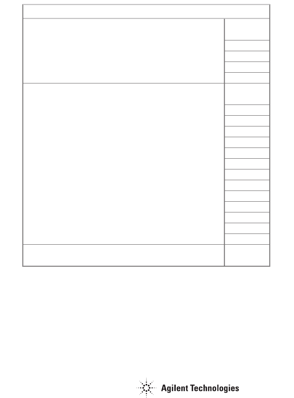
Attached is a routine maintenance schedule for atomic
absorption spectrophotometers (Figure 1). By adhering to this
program, the overall integrity of the atomic absorption spec-
trophotometer can be maintained and the laboratory analyst
will reap the benefits of increased instrument lifetime, reduced
downtime, and gain greater confidence in the analytical results.
www.agilent.com/chem
Agilent shall not be liable for errors contained herein or
for incidental or consequential damages in connection
with the furnishing, performance, or use of this material.
Information, descriptions, and specifications in this
publication are subject to change without notice.
© Agilent Technologies, Inc., 1984
Printed in the USA
November 1, 2010
AA039
Maintenance Schedule (Flame AA)
Daily Completed
1. Check Gas
2. Check Exhaust system with smoke test
3. Empty the drain receptacle
4. Clean lamp and sample compartment windows
5. Rinse spray chamber with 50-100 mL of distilled water
Weekly
1. Disassemble spray chamber
(a) Check glassbead
(b) Check nebulizer components
(c) Wash the spray chamber and liquid trap
(d) Scrub the burner
(e) Change the liquid in the liquid trap
(f) Check the O-rings
2. Check air filter assembly
3. Wipe off instrument
4. At Time of Gas Tank Change
5. Check for leaks
6. Check for operation of the regulators
7. Check for operation of the shut off valves
8. Check the gas supply hoses
Yearly
1. Schedule an Agilent service engineer to perform Preventive Maintenance
Figure 1. Routine maintenance schedule for atomic absorption spectrophotometers.
For More Information
For more information on our products and services, visit our
Web site at www.agilent.com/chem
