
AESTHETIC ASSEMBLY - THE ART TO ATTRACTIVE BONDING
By Miranda Marcus
Dukane Intelligent Assembly Solutions
Abstract
After carefully molding a beautiful product, nothing is
worse than seeing it destroyed during assembly. Every
joining process is capable of causing marking, flash,
particulate, damage to appendages, or other aesthetic
defects. However, with proper part design and processing,
a finished weld can be imperceptible or even a cosmetic
asset. The art to attractive bonding is specific to each
process or type of product. Whether processing parts
through ultrasonic, spin, vibration, hot plate, laser welding
or thermal staking, methods do exist to improve the
appearance of the overall product after bonding.
Introduction
Welding is a common necessity for a wide variety of
industries, including automotive, medical, electronics, and
consumer products. Whether there are components that
must be securely enclosed or the part geometry is too
complex to be processed in one piece, a secondary joining
step is often required.
A wide variety of products must have aesthetic welds,
or bonds. Packaging, especially clamshells, are probably
the most prominent example. Some other demanding
cosmetic applications are vehicle headlamps and taillights,
spoilers, battery enclosures, medical devices, toys,
dishware and utensils, electronics housings, facemasks,
fencing, furniture, and filters. For these products, and
many others, melt flow must be contained, flash or
particulate eliminated, tool marks prevented, and any other
part damage eradicated.
The methods for preserving cosmetics are as varied as
the welding processes available. Each assembly process
can produce its' own variety of decorative debacle.
Fortunately, for each potential aesthetic issue, there is a
solution.
Ultrasonic Welding
Ultrasonic welding uses piezo-electric ceramics that
convert electrical current into mechanical motion. High
frequency (15 kHz up to 90 kHz) vibrations are transmitted
through the plastic part to the joint where intermolecular
stress and strain cause melting of the surface of both parts,
and welding. Ultrasonic welding is used for a wide variety
of applications including clamshells, electronics housings,
medical applications, and fabric welding.
Joint Design
One of the most common cosmetic defects that result
from ultrasonic welding is flash; melted material that is
pushed out of the joint at the weld interface. In addition to
being unsightly, this flash can also be a functional defect in
certain applications. For example, air or water filter
housings usually cannot have flash internally.
Fortunately, flash can be easily avoided through
proper joint design. Generally, in production, there is
balance between weld strength and amount of flash. In
order to get greater strength, more collapse of the joint is
required, and more flash is produced. Simply adding a
flash trap to the part design, however, can allow sufficient
strength with no flash. Figure 1 shows some common
ultrasonic joints that can effectively hide flash and produce
a strong weld.
Figure 1: Ultrasonic Joints that Hide Flash
De-Gating
A second common defect with ultrasonic welding is
de-gating of small features in the assembly during the
weld. Because ultrasonics depends on high frequency
vibration of the parts, there is a chance for cracks to form
in areas with sharp corners or small cross-sectional areas.
Sometimes these cracks are so severe that small features
can be complete sheared off, or de-gated.
There are two main ways to prevent this type of
damage. Either increase the radii or cross-section of the
troubled area, or decrease the amplitude of the process.
However, reducing amplitude often has a negative impact
on the weld, as it essentially reduces the energy available
to weld the parts. Therefore, whenever possible, it is best
to eliminate small or fragile features when ultrasonic
welding will be used.
\
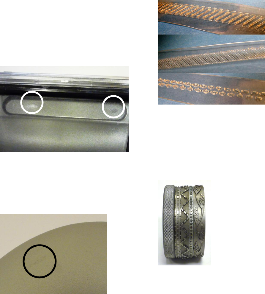
Surface Marking
When welding textured parts, there is a strong
possibility that the ultrasonic horn will mar the contact
surface. On textured surfaces, there may be shiny places
where the texture has been removed during welding. To
prevent this occurrence, simply put a layer of thin film
between the part and the horn. Figure 2 shows an example
of this type of cosmetic flaw.
Figure 2: Ultrasonic Welding can cause damage to the
parts texture.
Marking can also occur when the horn leaves a residue
on the part, see Figure 3. This is most often seen with
aluminum horns or with titanium horns that are welding
white parts. Using chrome plated aluminum horns is the
best way to prevent this type of problem.
Figure 3: Ultrasonic welding with an aluminum horn can
leave residue on the part.
Film & Fabric
As mentioned in the introduction, clamshell packaging
is one of the biggest areas where cosmetic assembly is
required. Ultrasonic welding is one of the processes most
often used for such applications. A wide range of weld
patterns have been developed to improve the appearance of
such welds. Figure 4 shows some common welding
patterns used for clamshells.
Figure 4: Examples of patterns used to weld clamshells
These same patterns can also be used for welding of
fabrics, as is often done for shower curtains, plastic bed
sheets, or even clothing. In fact, fabrics can be welded
using ultrasonics, very similarly to how they can be sewn,
using a rotating anvil under a stationary horn that is
operated by a foot pedal. An even wider range of attractive
patterns can be used for fabric welding; some are shown in
Figure 5 below.
Figure 5: Patterns used to weld film or fabric
Spin Welding
Another common welding process is spin welding. In
this process, one of the parts is held stationary, and the
other is spun at high revolutions per minute to generate
frictional heat at the circular joint. While spinning, the
parts are pressed together to form a weld. Spin welding is
often used to join pipes, insulated cups or bowls, and filter
housings, among others.
Joint Design
The biggest drawback, cosmetically, to spin welding is
that it generates a significant amount of flash. Unlike
ultrasonic welding, the parts are moving during the weld
process, meaning that the melt layer is also in motion.

Subsequently, more melt must be generated to ensure good
contact between the parts and a strong weld. Figure 6
shows an example of the type of flash generated during
spin welding.
Figure 6: Spin weld flash
Therefore, for every application where aesthetics is a
concern, the part should be designed to hide that melted
material, some weld joints that can hide flash are shown in
Figure 7. With out-of-round parts, however, it is often not
possible to contain the flash simply by using a different
joint design. In these instances, a secondary flash removal
step is required.
Figure 7: Spin weld joint designs that can hide flash
while providing a strong weld.
Particulate
In addition to solid pieces of displaced material, spin
welding tends to generate particulate (tiny particles of
plastic dust). Most times, this can be blown out after
welding, but sometimes it cannot be present at all (as with
medical or food industry applications). Reducing the
rotational spin welding speed reduces the generation of
particulate. Additionally, soft materials like polypropylene
tend to produce much more particulate during welding, as
shown in Figure 8.
Figure 8: Spin welding particulate
Tooling Marks
Like most other welding processes, there is the
possibility of leaving tooling marks on the parts.
Typically, this occurs on the upper part when it is not
securely held in place using designed driving features.
Tooling marks occur when the upper part slips in the tool.
When the fixture is made of urethane, this can cause black
marks on the parts. When it is made from stainless steel or
aluminum, it can leave gouges in the parts, see Figure 9.
Figure 9: Spin welding tooling marks
To avoid this type of marking, it is essential to provide
driving features on the part itself. A "driving feature" is
simply some type of protrusion or depression on the upper
part upon which the upper tool can apply rotational force.
In addition, the parts should have relatively consistent
external dimensions.
Vibration Welding
Vibration welding is one of the most often used
welding processes for large parts, such as vehicle
headlamps and taillights, glove boxes, intake manifolds,
fencing, and even furniture. In this process, one part is
held stationary while the other is vibrated horizontally on

top of it at low frequency (120 Hz - 240 Hz) and high
amplitude. During this vibration, the upper part is also
pressed down on to the lower part to create the weld.
Joint Design
Vibration welding depends on the movement of large
amounts of melted material to generate a weld. Therefore,
for this process as well, the joint design is critical for flash
containment. With the proper design, a strong flash free
weld can be achieved consistently. Figure 10 diagrams
some joint designs that can produce a strong weld with no
flash.
Figure 10: Vibration joint design diagrams
De-Gating
As with ultrasonic welding, the movement of the parts
during vibration weld can cause de-gating of small
features. The high amplitude used in vibration welding
causes excess stress on large projecting features. De-
gating is especially likely to occur when the base of the
feature has a small cross-sectional area or sharp corners.
Tooling Marks
Vibration welding is similar to spin welding in that
driving features on the part are required to prevent tooling
marks. In the absence of such features, a knurl pattern may
be used to grip the part. The use of a knurl, however, will
cause abrasions on the part, as shown in Figure 11.
Figure 11: Vibration welding tools often use knurling to
grip the parts.
If such marking is not acceptable a urethane upper
tool combined can sometimes be used to prevent scratches
on the part. Often, a vacuum must be used with urethane
tooling to provide sufficient holding force. Whatever
tooling material is used, the parts must still be kept as
dimensionally consistent as possible.
Hot Plate Welding
In hot plate welding, the two parts to be joined are
pressed against or brought into close proximity of a heated
surface to generate a melt layer, then pressed against each
other to complete the weld. In this style of welding, the
joint may be contoured quite extensively and strong
hermetic welds are generally achievable. Nothing can be
captured inside the parts, however, as any internal
components would be damaged by the hot plate. Hot plate
welding is often used for large pipes or tanks.
Joint Design
Although hot plate welding generates a lot of flash, it
is the most controlled, good-looking flash of any weld
process. The melted material pushed of the joint when the
two parts are pressed together forms a very nice rounded
line that can almost look as if it was designed to be there,
this can be seen in Figure 12. However, if the double line
of melt does not suit the application at hand, it can be
hidden with a change of joint design.
Figure 12: Hot plate flash can look very controlled and
nice
Out-Gassing
One of the unique potential cosmetic issues with hot
plate welding is out-gassing. When plastic is heated, it
emits gasses that can discolor the parts when they are
welded, especially on metalized surfaces. The effects of
out-gassing are identified in Figure 13. This can be
eliminated by applying a vacuum to one of the parts to
extract the fumes before they can cause any discoloration
or degradation.

Figure 13: Hot plate out-gassing
Warping
Due to the high heat input used in hot plate welding,
the parts can be warped during welding. The best way to
prevent this is to use thicker part walls. Excess warping
can also be avoided by using vacuums and clamping in the
tooling to keep the parts in the correct shape during the
weld.
Laser Welding
One of the newest polymer joining processes is laser
welding and is growing in popularity, particularly for
medical applications. This assembly method uses a
focused laser beam to heat the weld joint. The two parts
are simultaneously pressed together to create the weld.
Laser welds are known for being very clean; flash and
particulate free. Laser welding never causes de-gating of
features and generally never causes warping. Still, for
some components, there is potential for cosmetic defects.
Surface Degradation
If improperly set up, there is a chance that surface
degradation will occur during welding. This happens if the
top part absorbs too much of the laser energy or if the
bottom part absorbs too little. This can be somewhat
adjusted for by changing the focal point of the laser, but it
is best avoided by choosing the materials with good laser
welding properties at the outset.
Burning
The greatest potential for aesthetic flaws in an
established process is marring from dirt or dust that is
burned by the laser during the weld. Any dust in the path
of the laser will absorb the weld energy and cause a
disparity in the weld. To prevent this, it is important to
maintain the cleanliness of the lens and the weld joint.
Burning can also appear in the process set-up phase as
over-welding. An example of over-welding by laser is
shown in Figure 14. To resolve this issue, decrease
wattage to lessen the laser energy or increase the travel
speed of the laser. In some systems, over-welding can be
eliminated by adjusting the focus point of the laser so that
it is further from the part.
Figure 14: Laser over-welding causes burns at the
joint
Thermal Staking
Thermal staking is a method of mechanically bonding
two parts by melting and reforming one of the parts to
contain the other. Most often, a post on the part with the
lower melting temperature is melted and formed into a
dome shape to hold in the second part, similar to a rivet.
Thermal staking is frequently used to contain circuit boards
or to replace screws on consumer products.
Stake Design
The most common cause of unattractive stakes is
improper post or tool detail design. It is vital that the
staking detail has the same volume as the unformed post.
If it is too small, excess material can be pushed out around
the base of the stake. If it is too larger, the detail will be
only half-formed and uneven in appearance. Figure 15
shows two of the most common staking detail design.
Figure 15: Thermal staking design diagrams
Sticking
Even if the post and staking detail are properly
designed, however, there is a chance that the formed dome
can be marred if the melted material sticks to the thermal
tool. This is especially common with soft materials, like
polyethylene. Happily, it can easily be avoided through
temperature modulation and the use of post cool. Figure
16 shows the type of stringy wisps of material that can be
left behind when the parts sticks to the thermal tool.
Dome
Rosette

Figure 16: Thermal sticking
Conclusion
If an application must be beautiful, then it is best to
begin considering the assembly method early in the design
process. Most of the common cosmetic defects can be
avoided with proper part design. Planning for aesthetic
assembly in these early stages will help allow a widened
processing window in production and reduce reject rate.
However, if a part is already in production without having
planned for the welding process, do not panic. There is
plenty that can be done to prevent unsightly flash, marking,
or other defects. Figures 17-20 show some examples of
attractive welds.
Figure 17: A well-designed ultrasonic joint results in a
strong, flash free, weld
Figure 18: An attractive spin weld, free of tool marking,
particulate, and flash
Figure 19: A properly designed vibration joint shows no
flash
Figure 20: Laser welding is one of the cleanest joining
methods available. Photo courtesy of Leister Corporation.
Figure 21: A nicely formed thermal stake
