
RTS
INSTALLATION GUIDE
This guide covers all Resonate Temperature Sensor models.
The Resonate temperature sensor product family includes:
RTS-1T-nW Temperature sensor
RTS-1H-nW Temperatureandrelavehumiditysensor
RTS-1TS-nW, Temperature sensor with temperature set point
RTS-2HS-nW Temperature and humidity sensor with temperature set point,
fanspeedandoccupancybuon
The character n is replaced with U for 902MHz, Y for 868MHz and J for 928 MHz radios.
Thepackageincludesthetemperaturesensorandinstallaonguide.
NOTE: The RTS is a solar powered device that absorbs solar energy storing it for use during low
light periods. Before assigning the RTS device to a receiver/ controller, the device should be
exposed to a good light source for a minimum of 2 hours.
3
The temperature sensor (also referred to as the sensor in this guide) is a wireless, energy
harvesngsensorthatmonitorsroomtemperatureintherangeof0-40°C(32°-104°F)
andrelavehumidityintherangeof0-100%.Thesensorisintendedforindooruseonly.
Some models have a temperature set point knob and/or a fan speed slide switch. These
oponsprovidetheuseraninterfacetomanuallyadjusthowthetemperaturecontrol
operates.
Abuononthelowerrightedgeofthesensorbodycanbeusedtoinvokeanoccupancy
event(forRTS-2HSmodels)ortogointotestmode(whenthebuonishelddown,see
“TestOperangModes”).
The temperature sensor transmits to a receiver which is typically a device that is
programmed to provide temperature control in the space that the sensor is monitoring
for closed loop temperature control. The sensor and receiver must be within range,
preferably in the same room and installed within 50’ (15.2 m) of each other. For
applicaonsexceeding50’(15.2m)range,greatercaremustbetakentoinsureproper
receponofthesensorstransmissionsatthereceiver,refertosecons“TestOperang
Modes”and‘InstallingWirelessDevices”.
Even with a brief exposure to light the sensor will operate; however for best results the
sensorshouldbemountedinalocaonwithexposureof4hoursofnaturalorarcial
light on a daily basis.
Thetemperaturesensortransmitsstatustelegramsthatcontaintheinformaondened
withinaequipmentprole.
Thetemperaturesensorsupportsthefollowingproles:
• A5-02-05: Temperature Sensor
• A5-04-01:TemperatureSensor+HumiditySensor
• A5-10-03:TemperatureSensor+TemperatureSetPointControl
• A5-10-19:Temperature+Humidity+SetPoint+FanSpeed+OccupancyBuon.
The valid ranges for each data element:
• Temperature:0-40°C,(32°-104°F)
• TemperatureSetPoint:osetscale0-250
• HumiditySensor:0-100%RH
• FanSpeedSwitch:Auto,OFF,Low(1)Med(2),High(3)
• OccupancyBuon:Occupied
- The temperature sensor will record
the temperature, temperature set point and humidity values* every 10 seconds
(sample period) when there is approximately 100 lux (10 foot-candles) available.
If there is less than 100 lux (10 fc), the sample period will increase to 100 seconds.
Aer24hoursat<15lux(1.5fc)thesampleperiodwillincreaseto200seconds.
*Assumingsucientstoragechargetooperate.
-Userscanadjustthetemperaturesetpointbyrotang
the knob counterclockwise to lower the set point value; clockwise to increase
the set point value.
The receiving temperature control equipment must scale the set point range to
valuesthatareapplicablefortheapplicaon.
-Userscanadjustthefanspeedswitchbyslidingtheswitchto
aseng:Auto,OFF,Low(1)Med(2),High(3).
4
- (RTS-2HS models only) Users can override a room occupancy
statebypressingtheoccupancybuononthelowerrightedgeofthesensor.
- LEDs are on the right side of the solar panel. The red LED will
ashwhentheLinkorOccupancybuonispressed.SeeTestOperangModes
forfurtherLEDinformaon.
- The temperature sensor will transmit a telegram when:
• 10 sample periods have been completed or
• whenthefanswitchoroccupancybuonareusedor
• whenthetemperaturevaluedierencefromthelasttransmiedvalueis
greaterthan0.3°C,(0.5°F)orthehumidityvaluedierencefromthelast
transmiedvalueisgreaterthan3%.
The temperature sensor can be mounted on any surface; glass, stone, concrete,
wallboard,cubicleparons,etc.Thesensorcanbemountedusingscrews(not
supplied) through the removable back plate (2 keyholes or using double sided
tape or Velcro™ (not supplied).
The mounng locaon of the wireless transmier is important as this will
directlyaectthereceiversreceponofthetelegrams.Beforeinstalling,refer
totheseconsintheguidedetailingtheinstallaonofwirelessdevices,layout
psandthetestoperaonmodes.
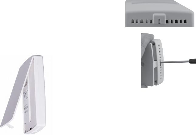
1. The sensor has a removable back plate.
The back plate has a security feature which
requires a tool for the removal of the
device from the backplate. To remove the
sensor,insertaatheadscrewdriver,intothe
slot and exert torque on the key tab to separate
the backplate from the housing body as shown in
the photos. Once the tab is free,
pull the body away from the back
plate.
2. Mount the back plate to
a bracket or the wall surface
inavercalorientaonwith
theplasckeyontheboom.Therearekeyholesinthe
back plate that mate with standard electrical box screw
paerns.Alternavely,youcanmountthesensorusing
double sided tape or Velcro® (not supplied).
3. Once the back plate has been secured to the wall or
mounngbracket,alignthetwotopalignmenttabsonthe
back plate with the temperature sensor body and press the lower edge
overtheplasckeyunlitclicksinplace.
This process requires the controller or receiver to be mounted and powered and

5
within range of the temperature sensor to be linked.
The sensor is a solar powered device that absorbs energy through a solar
panel storing it for use during low light periods. Before assigning the sensor to
a receiver/controller, the device must be exposed to a good light source for a
minimumof2hours,orinstalltheoponalstartassistbaery(notsupplied).
1. Remove the sensor from the back plate by pressing in
on the tab on the lower edge and pulling away from
the back plate.
2. AcvateLEARNorLINKmodeatthereceiver,if
necessaryrefertothemanufacturersdocumentaon.
3. PressthetemperaturesensorsLink(Teach)buon.
4.DeacvateLEARNmodeatthereceiver.
The baery is not required for normal operaon when the RTS receives
adequatenaturalorarciallight.Thebaerycanbeusedduringinstallaon
(start assist).
1. Remove the sensor from the back plate by pressing the key on the lower
edge of the sensor body and pull the body away from the back plate.
2. Toremoveoldbaery:Usingasmallatheadscrewdriverorpenasalever,
insertpointedendundertheclearplascbaeryretainingclip’sedgeand
poptheclipo.
3. Installorreplacethebaeryintheclipwithanew
CR2032coincellbaeryinsuringtheposiveside(+)
will be facing up.
4.Align the two straight edges of the retaining clip with
thebaeryholderandpresstheclipinwithyour
nger.
EnsuretheRTSisfullychargedbeforeenteringtestmodes.Inserngabaery
during test modes is also recommended. The following tests can be selected
when in test mode.
provides visual feedback of the
immediate energy produced by the solar panel.
1. To enter Light Level Test mode, press and hold the
occupancy/testbuonfor6seconds.Thegreen
LED will begin to blink.
2. Pressthetestbuonagainfor6secondsto
select Light Level Test. The green LED will blink
inaccordancetothelightlevelitisdetecng.
Thiswillchange(2secondlagme)asyoumovethesensortoareaswith
dierentlightlevels.Seefollowingblinkindicatortable.
Note:Enteringtestmodesecon:Ifthe redLED blinks(nogreenLED)aeryou have

6
releasedthetestmodebuon,place thesensorunderalampwith at least100foot-
candles (1000 lux) for 1 hour before retrying.
0,1 <15 <1.4 belowoperanglevel n/a
2 15-50 1.4-4.6 minoperanglevel n/a
3 50-100 4.6-9.3 24hourstofullcharge 100 hours
4 100-200 9.3 - 18.6 12 hours to full charge 150 hours
5 200-400 18.6 - 37.2 6 hours to full charge 200 hours
The me to fully charge is based on the storage capacitor charging from a
non-operaonal condion.Discharge me indicates how long a fully charged
sensor will operate in the dark. The test will repeat every 2 seconds and run for
aduraonof100seconds.Youmayquitthetestatanymebypressingthetest
buonfor6seconds.
provides visual feedback of the sensors signal
strengthbyalinkedreceiverwithrangeconrmaoncapability(only“Fseries”
controllershaverangeconrmaonability).Oneandonlyonereceivercanbe
linkedtothesensorforproperoperaonofthetest.(disablerepeatersinrange
forpropertestoperaon).
1. ToenterRangeConrmaonTestmode,pressandholdtheoccupancy/
testbuonfor6seconds.Thegreenledwillbegintoblink.
2. Aquickpressandreleaseofthebuonatthispointwillallowyoutoselect
betweenlightleveltest(greenLED)andrangeconrmaontest(amber).
When the amber LED is blinking, go to step 3. (If the 3 LEDs fail to blink
during this test, place under a lamp with at least 100 fc (1000 lux) for 1
hour before retrying.)
3. Pressandholdthetestbuonagainfor6secondstoselectRange
ConrmaonTest.
All three LED’s can blink in this test mode when the sensor transmits or receives
a Range Conrmaon Telegram. The sensor will display the signal strength
status for 5 seconds, see table below.
Green > -70 dbm
Amber > -80 dbm
Red <-80dbm
The test will repeat every 10 seconds and run for a duraon of 3 minutes.
Youmayquitthetestatanymebypressingtheoccupancy/testbuonfor6
seconds.

7
Carefulplanningisneededwhenlocangthereceiversandtransmiersbased
ontheconstruconmaterialsinthespaceandpossibilityoftenant’sfurniture
disrupngthetransmissions.
The temperature sensor should be installed in the space where the receiver is
mounted and connected to the temperature control equipment however the
signal will travel through material barriers.
Refertothetablesbelowforrangeconsideraonswithbuildingmaterialsthat
reduce the radio signal power.
Wood 0-10%
Plaster 0-10%
Glass 0-10%
Brick 5-35%
MDF 5-35%
Ferroconcrete 10-90%
Metal 90-100%
Aluminum 90-100%
Line of sight: 80’(24m)corridors
Line of sight: 150’(46m)openhalls
Plasterboard: 80’(24m)through3walls
Brick 33’ (10m) through 1 wall
Ferroconcrete 33’ (10m) through 1 wall
Ceiling: Not Recommended
• Avoidlocangtransmiersandreceiversonthesamewall.
• Avoidlocangtransmiersandreceiverswherethetelegramsmust
penetrate walls at acute angles. This increases the material the telegram
must pass through reducing the signal power.
• Avoidlargemetalobstruconsastheycreateradioshadows.Place
receiversinalternatelocaonstoavoidtheshadoworuserepeaterstogo
around the obstacle.
• Donotlocatereceiversclosetootherhighfrequencytransmiers.Leave
at least 3’ (1 m) between the receiver and any other source of interference
including,ballasts,LEDdrivers,computers,videoequipment,Wi-Fi/LAN
routers,GSMmodemsandmonitors.Transmiersarenotaectedby
these sources of interference.

8
BuiltinanISO9001ceredfacility
FCCPart15.231
(902 MHz models only)
ContainsFCCID:TCM300U
TheencloseddevicecomplieswithPart15oftheFCCRules.
Operaonissubjecttothefollowingtwocondions:
(I.) this device may not cause harmful interference and
(ii.) this device must accept any interference received, including
interferencethatmaycauseundesiredoperaon.
ICRSS-210(902 MHz models only)
ContainsIC:5713A-STM300U
CE (868 MHz models only)
CEMarking
ARIB STDT108 (928MHz models only)
ComplieswiththeJapaneseradiolawandisceredaccordingtoARIBSTDT108.
Thisdeviceshouldnotbemodied(otherwisethegranteddesignaon
number will become invalid)
Copyright2013-2018EchoexSoluons,Inc.
Specicaonssubjecttochangewithoutnoce.
Echoflex Solutions
38924 Queens Way, Unit #1, Squamish, BC, V8B 0K8, Canada
n
+1 778-733-0111
echoflexsolutions.com
n
8DC-5327-2.3
n
Document Part # 8188M21-5327-1 Rev F
n
12/18
